501-25-4
Body Repairs - General Information
501-25-4
DESCRIPTION AND OPERATION
Description and Usage of Body Repair Literature
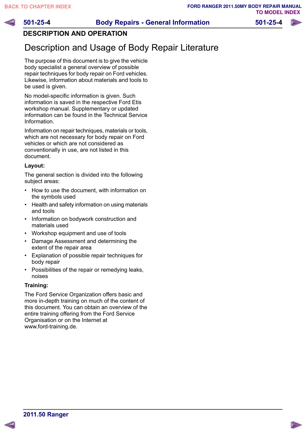
The purpose of this document is to give the vehicle
body specialist a general overview of possible
repair techniques for body repair on Ford vehicles.
Likewise, information about materials and tools to
be used is given.
No model-specific information is given. Such
information is saved in the respective Ford Etis
workshop manual. Supplementary or updated
information can be found in the Technical Service
Information.
Information on repair techniques, materials or tools,
which are not necessary for body repair on Ford
vehicles or which are not considered as
conventionally in use, are not listed in this
document.
Layout:
The general section is divided into the following
subject areas:
How to use the document, with information on
the symbols used
Health and safety information on using materials
and tools
Information on bodywork construction and
materials used
Workshop equipment and use of tools
Damage Assessment and determining the
extent of the repair area
Explanation of possible repair techniques for
body repair
Possibilities of the repair or remedying leaks,
noises
Training:
The Ford Service Organization offers basic and
more in-depth training on much of the content of
this document. You can obtain an overview of the
entire training offering from the Ford Service
Organisation or on the Internet at
www.ford-training.de.
501-25-5
Body Repairs - General Information
501-25-5
DESCRIPTION AND OPERATION
Symbols
Warnings and hazard notices
Warnings and hazard notices are shown in this
literature by WARNING, CAUTION and NOTE
indicators. These notices are always shown before
a job step which can be associated with an
immediate personal or material danger.
WARNING: This notice is used when failure
to exactly follow the instructions given in
this literature or failure to follow them at
all may result in a hazard to persons and/or
in persons being injured.
CAUTION: This notice is used when failure
to exactly follow the instructions or test
procedures given in this literature or failure
to follow them at all may result in damage
to the vehicle or to components.
NOTE: This notice is used when the operator
should be made aware of special or extra
information.
Symbols used
Symbols are used to graphically represent
additional information about the operation, tool or
materials. This information will not be shown
separately again as text.
The symbols used in this and other body repair
manuals may be used alone as well as in
combination in a diagram.
All the symbols used in these documents can be
found in the General Information section.
For additional information, refer to: Symbols
Glossary (100-00 General Information,
Description and Operation).
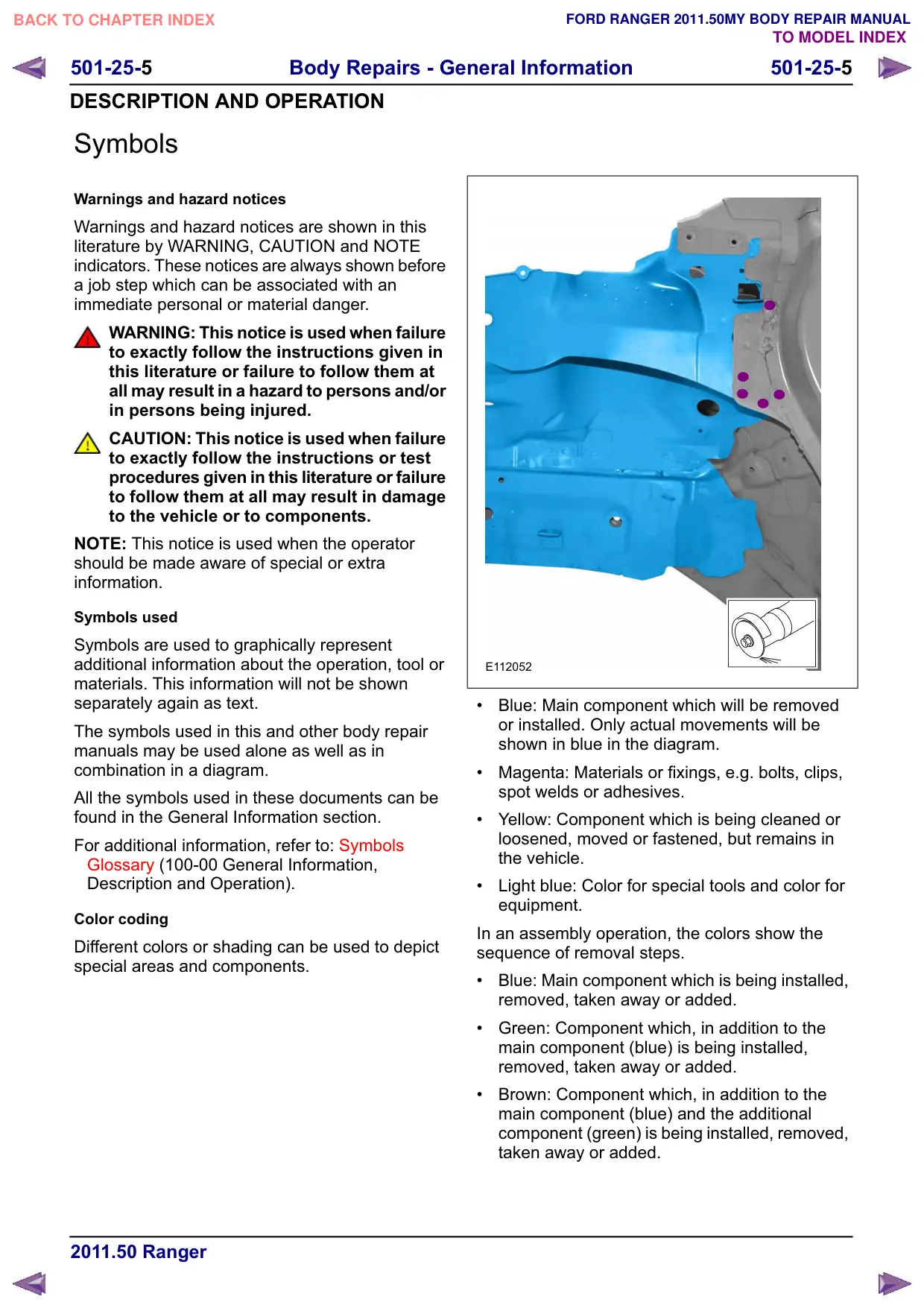
Color coding
Different colors or shading can be used to depict
special areas and components.
E112052
Blue: Main component which will be removed
or installed. Only actual movements will be
shown in blue in the diagram.
Magenta: Materials or fixings, e.g. bolts, clips,
spot welds or adhesives.
Yellow: Component which is being cleaned or
loosened, moved or fastened, but remains in
the vehicle.
Light blue: Color for special tools and color for
equipment.
In an assembly operation, the colors show the
sequence of removal steps.
Blue: Main component which is being installed,
removed, taken away or added.
Green: Component which, in addition to the
main component (blue) is being installed,
removed, taken away or added.
Brown: Component which, in addition to the
main component (blue) and the additional
component (green) is being installed, removed,
taken away or added.
501-25-6
Body Repairs - General Information
501-25-6
DESCRIPTION AND OPERATION
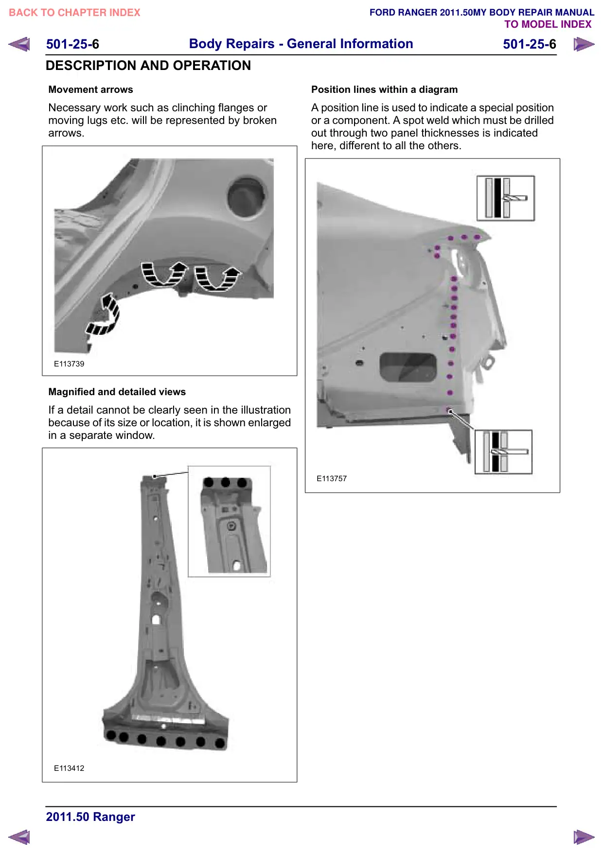
Movement arrows
Necessary work such as clinching flanges or
moving lugs etc. will be represented by broken
arrows.
E113739
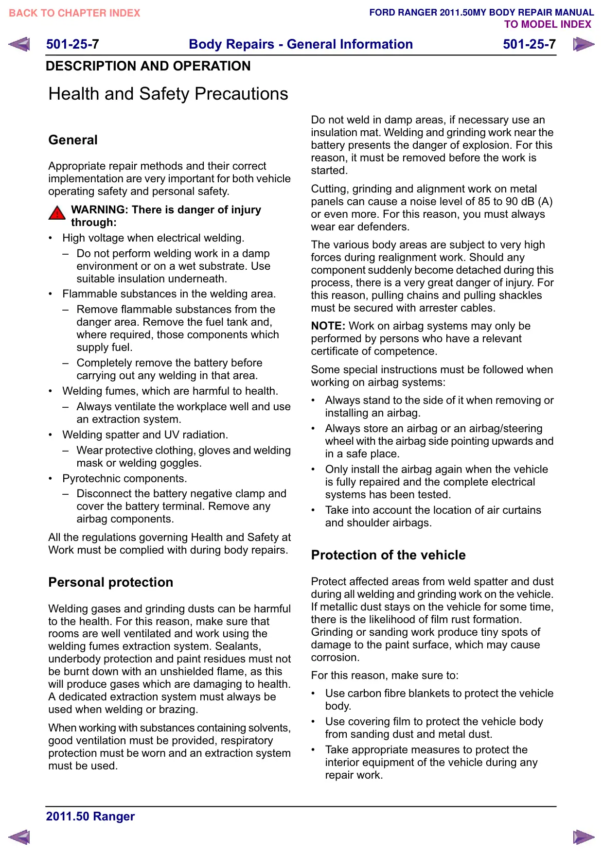
Magnified and detailed views
If a detail cannot be clearly seen in the illustration
because of its size or location, it is shown enlarged
in a separate window.
E113412
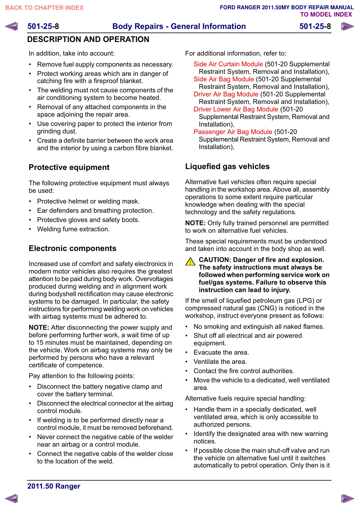
Position lines within a diagram
A position line is used to indicate a special position
or a component. A spot weld which must be drilled
out through two panel thicknesses is indicated
here, different to all the others.
E113757
501-25-7
Body Repairs - General Information
501-25-7
DESCRIPTION AND OPERATION
Health and Safety Precautions
General
Appropriate repair methods and their correct
implementation are very important for both vehicle
operating safety and personal safety.
WARNING: There is danger of injury
through:
High voltage when electrical welding.
œ Do not perform welding work in a damp
environment or on a wet substrate. Use
suitable insulation underneath.
Flammable substances in the welding area.
œ Remove flammable substances from the
danger area. Remove the fuel tank and,
where required, those components which
supply fuel.
œ Completely remove the battery before
carrying out any welding in that area.
Welding fumes, which are harmful to health.
œ Always ventilate the workplace well and use
an extraction system.
Welding spatter and UV radiation.
œ Wear protective clothing, gloves and welding
mask or welding goggles.
Pyrotechnic components.
œ Disconnect the battery negative clamp and
cover the battery terminal. Remove any
airbag components.
All the regulations governing Health and Safety at
Work must be complied with during body repairs.
Personal protection
Welding gases and grinding dusts can be harmful
to the health. For this reason, make sure that
rooms are well ventilated and work using the
welding fumes extraction system. Sealants,
underbody protection and paint residues must not
be burnt down with an unshielded flame, as this
will produce gases which are damaging to health.
A dedicated extraction system must always be
used when welding or brazing.
When working with substances containing solvents,
good ventilation must be provided, respiratory
protection must be worn and an extraction system
must be used.
Do not weld in damp areas, if necessary use an
insulation mat. Welding and grinding work near the
battery presents the danger of explosion. For this
reason, it must be removed before the work is
started.
Cutting, grinding and alignment work on metal
panels can cause a noise level of 85 to 90 dB (A)
or even more. For this reason, you must always
wear ear defenders.
The various body areas are subject to very high
forces during realignment work. Should any
component suddenly become detached during this
process, there is a very great danger of injury. For
this reason, pulling chains and pulling shackles
must be secured with arrester cables.
NOTE: Work on airbag systems may only be
performed by persons who have a relevant
certificate of competence.
Some special instructions must be followed when
working on airbag systems:
Always stand to the side of it when removing or
installing an airbag.
Always store an airbag or an airbag/steering
wheel with the airbag side pointing upwards and
in a safe place.
Only install the airbag again when the vehicle
is fully repaired and the complete electrical
systems has been tested.
Take into account the location of air curtains
and shoulder airbags.
Protection of the vehicle
Protect affected areas from weld spatter and dust
during all welding and grinding work on the vehicle.
If metallic dust stays on the vehicle for some time,
there is the likelihood of film rust formation.
Grinding or sanding work produce tiny spots of
damage to the paint surface, which may cause
corrosion.
For this reason, make sure to:
Use carbon fibre blankets to protect the vehicle
body.
Use covering film to protect the vehicle body
from sanding dust and metal dust.
Take appropriate measures to protect the
interior equipment of the vehicle during any
repair work.
501-25-8
Body Repairs - General Information
501-25-8
DESCRIPTION AND OPERATION
In addition, take into account:
Remove fuel supply components as necessary.
Protect working areas which are in danger of
catching fire with a fireproof blanket.
The welding must not cause components of the
air conditioning system to become heated.
Removal of any attached components in the
space adjoining the repair area.
Use covering paper to protect the interior from
grinding dust.
Create a definite barrier between the work area
and the interior by using a carbon fibre blanket.
Protective equipment
The following protective equipment must always
be used:
Protective helmet or welding mask.
Ear defenders and breathing protection.
Protective gloves and safety boots.
Welding fume extraction.
Electronic components
Increased use of comfort and safety electronics in
modern motor vehicles also requires the greatest
attention to be paid during body work. Overvoltages
produced during welding and in alignment work
during bodyshell rectification may cause electronic
systems to be damaged. In particular, the safety
instructions for performing welding work on vehicles
with airbag systems must be adhered to.
NOTE: After disconnecting the power supply and
before performing further work, a wait time of up
to 15 minutes must be maintained, depending on
the vehicle. Work on airbag systems may only be
performed by persons who have a relevant
certificate of competence.
Pay attention to the following points:
Disconnect the battery negative clamp and
cover the battery terminal.
Disconnect the electrical connector at the airbag
control module.
If welding is to be performed directly near a
control module, it must be removed beforehand.
Never connect the negative cable of the welder
near an airbag or a control module.
Connect the negative cable of the welder close
to the location of the weld.
For additional information, refer to:
Side Air Curtain Module (501-20 Supplemental
Restraint System, Removal and Installation),
Side Air Bag Module (501-20 Supplemental
Restraint System, Removal and Installation),
Driver Air Bag Module (501-20 Supplemental
Restraint System, Removal and Installation),
Driver Lower Air Bag Module (501-20
Supplemental Restraint System, Removal and
Installation),
Passenger Air Bag Module (501-20
Supplemental Restraint System, Removal and
Installation),
Liquefied gas vehicles
Alternative fuel vehicles often require special
handling in the workshop area. Above all, assembly
operations to some extent require particular
knowledge when dealing with the special
technology and the safety regulations.
NOTE: Only fully trained personnel are permitted
to work on alternative fuel vehicles.
These special requirements must be understood
and taken into account in the body shop as well.
CAUTION: Danger of fire and explosion.
The safety instructions must always be
followed when performing service work on
fuel/gas systems. Failure to observe this
instruction can lead to injury.
If the smell of liquefied petroleum gas (LPG) or
compressed natural gas (CNG) is noticed in the
workshop, instruct everyone present as follows:
No smoking and extinguish all naked flames.
Shut off all electrical and air powered
equipment.
Evacuate the area.
Ventilate the area.
Contact the fire control authorities.
Move the vehicle to a dedicated, well ventilated
area.
Alternative fuels require special handling:
Handle them in a specially dedicated, well
ventilated area, which is only accessible to
authorized persons.
Identify the designated area with new warning
notices.
If possible close the main shut-off valve and run
the vehicle on alternative fuel until it switches
automatically to petrol operation. Only then is it
501-25-
Body Repairs - General Information
501-25-
DESCRIPTION AND OPERATION
allowed to drive the vehicle into the workshop
or service area.
If possible do not allow any liquefied gas (LPG)
to escape.
The ambient temperatures must not exceed
40°C. For this reason the LPG and CNG fuel
tanks must be removed on vehicles with LPG
or CNG operation before using a drying oven
to dry the paint where the temperature exceeds
40°C.
Avoid situations in which fuel from an LPG or CNG
fuel tank can escape. These situations include:
Extremely hot ambient temperatures.
Parking near a heating device.
Raising the vehicle near a ceiling heater.
Refrigerated conversion vehicles
Apart from the special materials used in building
the structure of the refrigerated compartment, such
vehicles have special energy and refrigeration
systems which require special handling during
repair.
CAUTIONS:
Danger of injury. Work on the 230<SP>volt
system of the refrigeration equipment must
only be carried out by trained specialist
personnel.
The refrigeration system is filled with
refrigerant R134a. This can cause frostbite
if it contacts the skin. Pay attention to the
corresponding warning notices and
instructions in the chapter Air Conditioning
Systems.
NOTE: Work on the refrigerant circuit may only be
performed by persons who have a relevant
certificate of competence.
Vehicles with a refrigerated compartment are often
used to transport foodstuffs. For this reason,
additional hygiene regulations must be complied
with during repair work.
Aluminum and plastic are used to construct the
two different types of compartment found on
refrigerated vehicles.
The aluminum conversion is a very stable and
technically perfect variant. However, against this
the relatively high production costs and a lower
payload must be taken into account, because of
the weight of the aluminum conversion itself.
NOTE: Basic and in-depth training is offered on
the following topics. You will find an overview of
the complete range listed in the Training brochure
published by the Ford Service Organization.
The plastic conversion has developed into a light,
clean and economical alternative because of
constant further development of materials and
working techniques.
NOTE: The material combinations, the
workmanship and the working methods must
comply with the current food hygiene regulations.
For this reason, service and repair work on the
refrigerated conversion may only be performed by
authorized and specially trained technicians.
Refrigerated compartment constructions are often
made using both materials. The floor pan is made
of structured, slip-proof aluminum panels and the
wall and ceiling cladding is made of smooth
surfaced plastic elements.
CAUTION: PUR hard foam is flammable. If
PUR hard foam is overheated, it will burn
on its own with a brilliant yellowish flame.
It produces unpleasant choking and toxic
fumes. Special measures must be taken
when welding the vehicle body.
Polyurethane wall and ceiling elements are
manufactured using a sandwich principle. An
insulating polyurethane core is coated with food
grade ABS plastic on one side.
PUR hard foam does not decompose, is rot
resistant and is odorless. These properties make
it suitable for use as insulation.
Because of its closed cell structure, water uptake
by PUR hard foam is for the most part only a
problem at edges. Cut edges or other mechanically
worked surfaces must however be sealed with the
greatest care.
The conversion to a refrigerated vehicle is
performed as made-to-order production. The large
surfaces of the wall and ceiling cladding can be
changed and are particularly easy to repair.
If access to the back of a body panel section is
needed because of body straightening work, in
some circumstances it is cheaper to perform a
cut-out repair instead of removing an element.
The repair process is fully described in the Student
Information booklet Refrigeration System
Technology, Transit 2000.5 Freshline.
501-25-10
Body Repairs - General Information
501-25-10
DESCRIPTION AND OPERATION
Environmental Regulations
Orderly and responsible waste management is not
only very important for the protection of health and
the environment, but it also has great importance
where saving natural resources is concerned.
In body repair shops, since the introduction of the
EU directives on the avoidance of vehicle waste
and the promotion of return, re-use and recycling
of vehicles and their components (2000/53/EU),
more rigorous attention than before is also paid to
avoidance and recycling of waste materials.
NOTE: The organization of disposal in the
operation must comply with the country specific
waste regulations:
In this respect, body repair shops must take into
account and comply with the following
requirements:
Separate waste according to its recycling and
disposal methods.
Produce evidence for the correct transport and
disposal of waste.
NOTE: The organization of disposal in the plant
must comply with the requirements of the Waste
Avoidance and Management Act.
The avoidance and recycling of waste must always
take priority. However, despite all measures which
may be taken, waste cannot be completely
avoided.
NOTE: Useable waste which is not allowed in
household rubbish, must be disposed of as special
waste
All remaining waste must be treated as commercial
waste and disposed of according to the local
requirements.
Only applies to the EU:
The vehicle manufacturer is also under a legal
obligation since the older vehicle legislation came
into force throughout Europe in 2002.
This law covers the surrender, withdrawal and
environmentally friendly disposal of older vehicles
through the manufacturer.
The older vehicle legislation contains all the
necessary information for the environmentally
compatible disposal of older vehicles, starting with
preliminary handling involving the removal of all
operating fluids, deactivation of pyrotechnic
components, elimination of pollutants and then
further handling by dismantling components for
re-use and recycling.
501-25-11
Body Repairs - General Information
501-25-11
DESCRIPTION AND OPERATION
Body Construction
General
Under bodywork construction, a general distinction
is made between monocoque and non-monocoque
bodywork. The safety of the occupants is the main
consideration for all types of bodywork
construction. The front and rear sections are
designed so that they absorb the energy of the
impact via crumple zones. The use of modern
design and manufacturing methods and the use of
newly developed body panels (relating to their
deformation and strength properties) mean that,
despite the continuous weight-savings, all
safety-related requirements made of the
construction can be met.
TO BE UPDATED LATER
The rigidity of the bodywork is achieved by a panel
skin and panel cross-section with the largest
possible profile and therefore the largest resisting
torque (such as for instance the rocker panel).
Swage lines in the outer area of the bodywork
increase the stiffness and the natural vibration
frequency, to prevent possible drumming noises.
Integral body-frame
In this method of construction, coverings,
reinforcements, retaining panels and profiles are
permanently joined together using a variety of
joining techniques (gluing, spot welding, laser
welding, soft soldering or brazing). The
load-bearing function of the structure must always
be achieved in each case.
There is no distinction made between components
which are purely subject to bending/torsion or thrust
loads and parts which perform sealing/covering
functions (as in non-monocoque bodywork for
example). In modern passenger vehicles,
monocoque bodywork is very widespread and
offers the advantages of a lightweight and low-cost
construction.
The mounting points for ancillary components such
as doors and wings are permanently built into the
monocoque bodywork.
High rigidity of the bodywork is vitally important to
keep the elastic deformations low at the joins to
the ancillary components and to prevent noise
when driving. Small gap dimensions are therefore
501-25-12
Body Repairs - General Information
501-25-12
DESCRIPTION AND OPERATION
only possible on vehicles with very stiff bodywork.
With high bodywork stiffness, the construction can
exert an influence on the handling of the vehicle
(e.g. on poor road surfaces).
Advantages of monocoque bodywork:
Weight reduction.
Economical manufacturing technology.
High torsional rigidity and high flexural strength.
Defined deformation behavior at the front and
rear.
Maximum passive safety due to the strong
passenger compartment
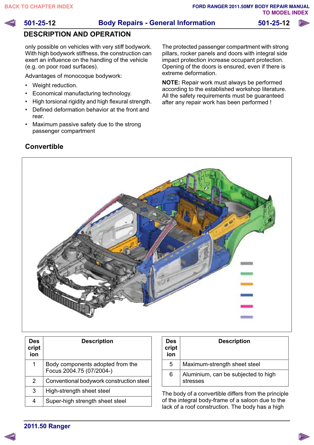
Convertible
Des
Description
FULSW
ion
1
Body components adopted from the
Focus 2004.75 (07/2004-)
2
Conventional bodywork construction steel
3
High-strength sheet steel
4
Super-high strength sheet steel
The protected passenger compartment with strong
pillars, rocker panels and doors with integral side
impact protection increase occupant protection.
Opening of the doors is ensured, even if there is
extreme deformation.
NOTE: Repair work must always be performed
according to the established workshop literature.
All the safety requirements must be guaranteed
after any repair work has been performed !
Des
Description
FULSW
ion
5
Maximum-strength sheet steel
6
Aluminium, can be subjected to high
stresses
The body of a convertible differs from the principle
of the integral body-frame of a saloon due to the
lack of a roof construction. The body has a high
501-25-13
Body Repairs - General Information
501-25-13
DESCRIPTION AND OPERATION
degree of torsional stiffness. This is achieved by
using high, super-high and maximum-strength
sheet steel and body reinforcements in
specifically-targeted areas.
These reinforcements can be installed in the area
of the doors (diagonal braces etc.) or on the
underfloor. In contrast to the saloon (or other
non-convertibles) with square-section side
members (closed profile), these reinforcements
have a profile which is open on the underside
(U-section).
Special constructional changes within the bodywork
structure:
Reinforcing or increase in the thickness of the
sheet steel in the pillar area.
Reinforcing or increase in the thickness of the
sheet steel in the floor pan structure (rocker
panel area).
Des
Description
FULSW
ion
1
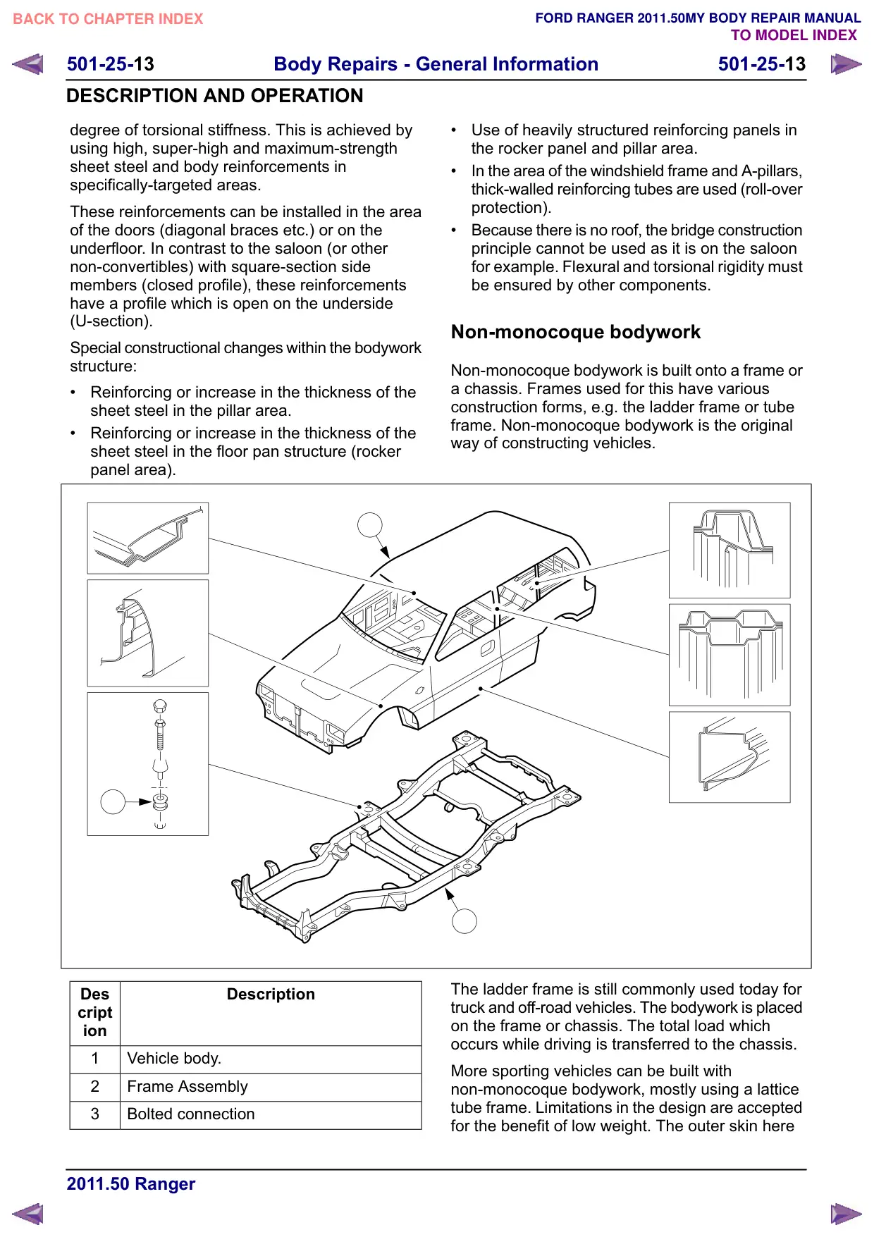
Vehicle body.
2
Frame Assembly
3
Bolted connection
Use of heavily structured reinforcing panels in
the rocker panel and pillar area.
In the area of the windshield frame and A-pillars,
thick-walled reinforcing tubes are used (roll-over
protection).
Because there is no roof, the bridge construction
principle cannot be used as it is on the saloon
for example. Flexural and torsional rigidity must
be ensured by other components.
Non-monocoque bodywork
Non-monocoque bodywork is built onto a frame or
a chassis. Frames used for this have various
construction forms, e.g. the ladder frame or tube
frame. Non-monocoque bodywork is the original
way of constructing vehicles.
The ladder frame is still commonly used today for
truck and off-road vehicles. The bodywork is placed
on the frame or chassis. The total load which
occurs while driving is transferred to the chassis.
More sporting vehicles can be built with
non-monocoque bodywork, mostly using a lattice
tube frame. Limitations in the design are accepted
for the benefit of low weight. The outer skin here
501-25-14
Body Repairs - General Information
501-25-14
DESCRIPTION AND OPERATION
is usually made of plastic or alloy. This type of
construction is also common in touring car racing
for instance.
Special features of non-monocoque bodywork
construction:
Partly large surface panels and high volume
shaped parts.
Thicker materials and greater reinforcements
in the frame area.
Floor pan as frame structure with high torsional
rigidity and flexural strength.
Side panels only make a small contribution to
the overall stability of the body.
Instructions for repair:
A different repair technique is necessary during
repairs. A deformed frame structure requires high
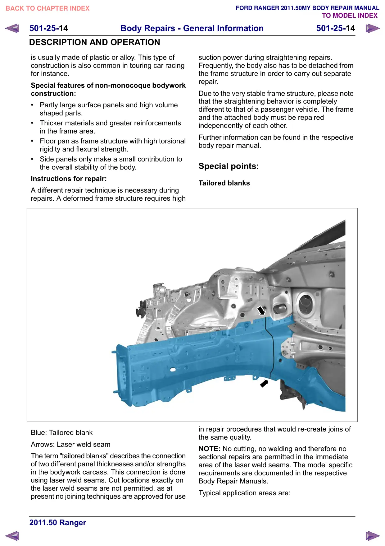
Blue: Tailored blank
Arrows: Laser weld seam
The term "tailored blanks" describes the connection
of two different panel thicknesses and/or strengths
in the bodywork carcass. This connection is done
using laser weld seams. Cut locations exactly on
the laser weld seams are not permitted, as at
present no joining techniques are approved for use
suction power during straightening repairs.
Frequently, the body also has to be detached from
the frame structure in order to carry out separate
repair.
Due to the very stable frame structure, please note
that the straightening behavior is completely
different to that of a passenger vehicle. The frame
and the attached body must be repaired
independently of each other.
Further information can be found in the respective
body repair manual.
Special points:
Tailored blanks
in repair procedures that would re-create joins of
the same quality.
NOTE: No cutting, no welding and therefore no
sectional repairs are permitted in the immediate
area of the laser weld seams. The model specific
requirements are documented in the respective
Body Repair Manuals.
Typical application areas are:
501-25-15
Body Repairs - General Information
501-25-15
DESCRIPTION AND OPERATION
Side member
Door inner reinforcement/door frames
Wheelhouses
Deformation behavior
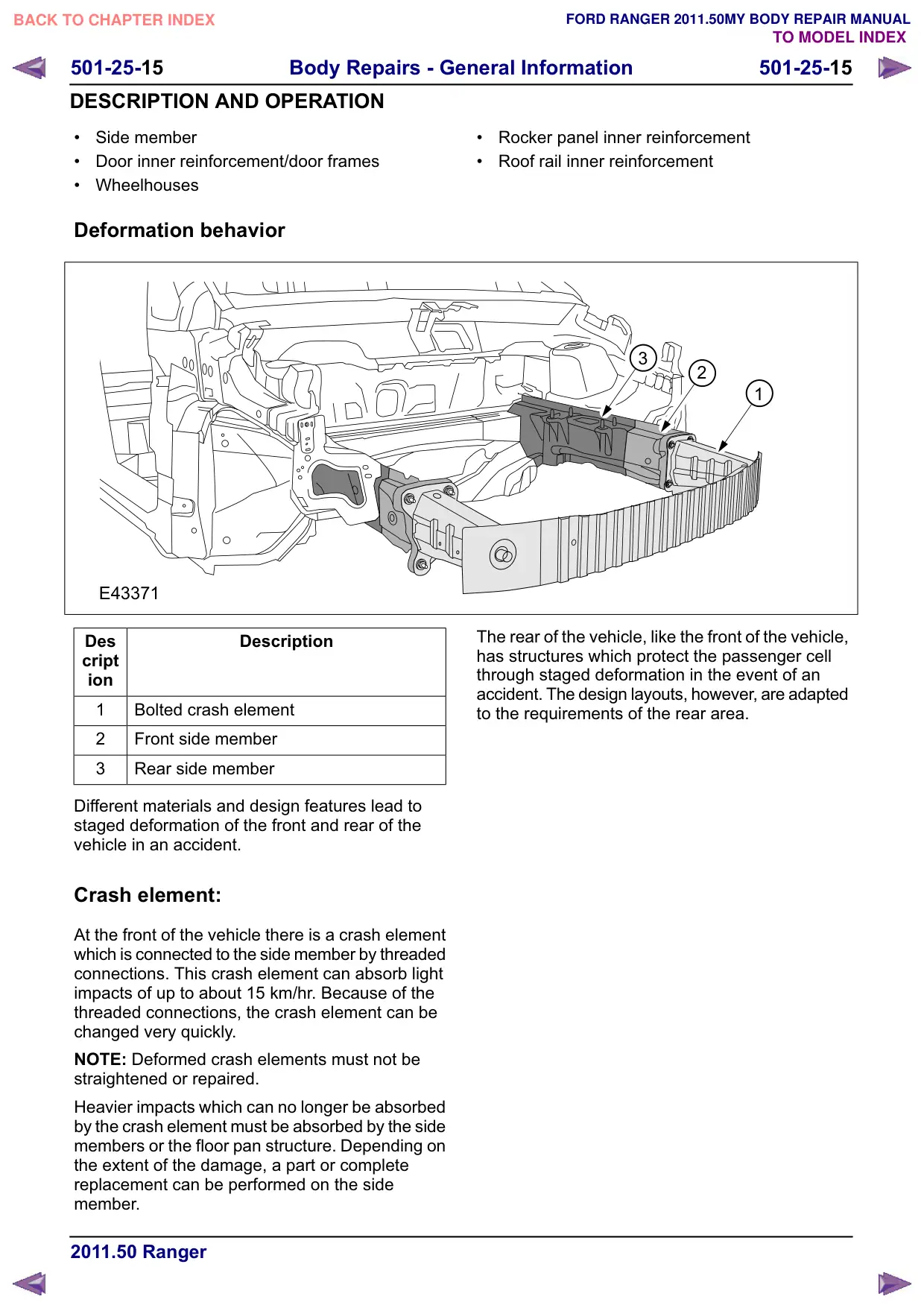
E43371
Des
Description
FULSW
ion
1
Bolted crash element
2
Front side member
3
Rear side member
Different materials and design features lead to
staged deformation of the front and rear of the
vehicle in an accident.
Crash element:
At the front of the vehicle there is a crash element
which is connected to the side member by threaded
connections. This crash element can absorb light
impacts of up to about 15 km/hr. Because of the
threaded connections, the crash element can be
changed very quickly.
NOTE: Deformed crash elements must not be
straightened or repaired.
Heavier impacts which can no longer be absorbed
by the crash element must be absorbed by the side
members or the floor pan structure. Depending on
the extent of the damage, a part or complete
replacement can be performed on the side
member.
Rocker panel inner reinforcement
Roof rail inner reinforcement
3
2
1
The rear of the vehicle, like the front of the vehicle,
has structures which protect the passenger cell
through staged deformation in the event of an
accident. The design layouts, however, are adapted
to the requirements of the rear area.
501-25-16
Body Repairs - General Information
501-25-16
DESCRIPTION AND OPERATION
Diagnosis and Damage Evaluation
Assessment of the extent of the damage includes
visual inspection and dimensional inspection of the
vehicle. In order to correctly determine the extent
of the damage caused by an accident, in-depth
technical knowledge, practical experience with the
technical equipment and the testing and measuring
devices is required.
Noticeable damage to the bodywork
structure
Positive accidental damage assessment can only
be achieved if the service technician is able to
reconstruct the effect of an impact on the body
structure.
For example:
If the impact occurs on the front left-hand side
member, the right-hand side member will usually
also have been damaged. Often the length of this
side member will not have changed, but because
of the rigid body design, it may have become
deformed. This damage can be detected through
the size of the gap between the door and fender
or by measuring the vehicle.
In the case of more severe impacts, in which the
front part of the vehicle cannot absorb all of the
impact energy, the passenger cell is also used to
absorb the energy. Here, the energy is transferred
via the A pillar and distributed there. This results
in deformations in the roof and the door sill.
NOTE: Because of existing damage to the
bodywork structure, damage diagnosis on a vehicle
lift may give extra incorrect diagnosis results.
NOTE: Training courses are offered on this subject.
For an overview, please refer to the Ford Service
Organisation's training course brochure.
If for instance the Ford Focus Coupé/Cabriolet is
raised on a vehicle lift, the dead weight of the
vehicle will cause the front end to drop by approx.
2 to 3 mm.
The altered door position is clearly recognizable
by stiffness of the lock; the door moves upwards.
This causes the lock pin to contact the guide
element of the door lock.
It is possible to draw conclusions about the extent
of the damage through a visual inspection of the
external damage. In general, the following areas
are to be checked during the visual inspection:
Outer panel including seam seals for cracks or
flakes in the paint caused by the accident.
Size of the gap on doors and hoods for
evenness.
Freedom of movement of door and hood/tailgate
locks.
The vehicle roof for folds (gap measurement on
vehicles with sunroof)
Dotted flange in door section for deformation
and cracked weld spots.
The side members and crash components for
crumpling and folding.
Trunk floor and floor pan from above and below
for crumpling.
No noticeable damage to the bodywork
structure
In addition to external indicators such as flaking
paintwork or cracks in the underbody protection, it
is vital to check for damage to the body structure
that is not visible from the outside (hidden body
damage) during a damage assessment. Unless
ancillary components are removed, it is often
impossible to achieve accurate diagnosis of the
underlying body parts.
NOTE: In order to determine the damage as
accurately as possible, it may be necessary to
remove ancillary components in the area of the
damage.
Particular attention must be paid to the following
components:
The A, B and C pillars in the roof area.
Floor pan.
Rear ancillary components, such as bumper,
lights, etc.
Trunk floor, spare wheel cavity.
Rear coverings, such as interior trim, carpet,
etc.
Lower rubber seals, e.g. in door area (welded
flange).
Area under the rear seat.
Attachment points of transmission system,
steering, engine, drive shafts, front and rear
axles.
Electrical components, e.g. the radio (damage
through shaking or through voltage peaks).
501-25-17
Body Repairs - General Information
501-25-17
DESCRIPTION AND OPERATION
Non-monocoque bodywork
The chassis and bodywork must always be
checked during damage diagnosis on vehicles with
non-monocoque bodywork.
It is also important here to inspect closely for
damage the impact area and the areas absorbing
forces.
With these vehicles, simple inspections can already
give an indication of possible deformations.
In addition, you must check for the following for
vehicles with frame structures:
Cracks in the paint on the frame welds.
Traces of deformation on frame components.
Check attachment points (silent blocks) for
position changes and damage.
Changed position of rubber seals.
Fit and function of the ancillary components.
501-25-18
Body Repairs - General Information
501-25-18
DESCRIPTION AND OPERATION
Body Sheet Metal
Types of steel
Steel body panels are still the most important
materials used in the fabrication of stressed skin
vehicle bodies. In addition to the familiar types of
steel, reinforced high-strength and also
ultra-high-strength special steels are used in
vehicle body construction.
Types of steels are classified by their properties of
strength and elasticity.
1
2
3
4
5
E116044
Pos.
Used type of steel
Application range
(Examples)
1
Ultra High Strengh
Impact Carriers,
Steel (UHSS)
Bumper Carriers, A-
B-Pillar Reinforce-
ments
2
Extra High Strengh
Frame Side
Steel (EHSS)
Member; Rocker
Reinforcements
3
Very High Strengh
Wheel House;
Steel (VHSS)
Structural Members
Normal strength steel has a minimum yield
strength of up to about 210 N/mm×.
High strength steels have a minimum yield
strength of about 150 to 600 N/mm×.
Ultra-high-strength steels have a minimum yield
strength of about 400 to 1200 N/mm×.
High-strength and ultra-high-strength steels are
mostly installed in safety relevant locations
(structural components). Among others, these are
side members, pillars, roof frames.
Pos.
Used type of steel
Application range
(Examples)
4
High Strengh Steel
Roof Sticks,
(HSS)
Fenders
5
Normal strength
Outer Panel
steels
Normal strength steels
Normal strength steels are most often used in body
construction. They are relatively soft and are
therefore particularly suitable for the deep drawing
501-25-19
Body Repairs - General Information
501-25-19
DESCRIPTION AND OPERATION
processes used in body manufacturing. As well as
very good reshaping properties, the panels also
have a relatively high rigidity.
High strength steels
The strength of the material and the nature of the
surface can be changed as required by different
engineering processes. In order to achieve suitable
configuration and a good match between
construction specifications and what is possible in
production, a large range of high strength panels
is available.
The range of the minimum yield strength is from
180 N/mm× to 460 N/mm×. High strength thin steel
panels usually have a surface finish. Electrolytic
surface sealing is preferred. Within the group of
high strength steels, various types of steel are used
in body construction:
Micro-alloyed high strength steels for very
difficult drawn components such as fenders, the
internal components of doors, hoods and
luggage compartment lids or load bearing
components such as sidemembers,
crossmembers etc.
Bake-hardening steels and phosphorus
alloyed steels for external panel components
with higher draw depth and subject to higher
operational demands.
Isotropic materials for flat shaped outer steel
panels on doors, hoods, luggage compartment
lids, roofs.
Ultra-high-strength steels
These steels are predominately used for body
structural components which are relevant to safety.
Despite the reduced thicknesses of the panels
used, weight reduction is often achieved together
with greater strength. As with high-strength steels,
special types of steel are used in the
ultra-high-strength steels group:
Complex phase steels are used for door side
impact carriers, bumper carriers and body
components relevant to crashes. Besides high
strength, they have good cold reshaping
properties and are easily welded.
Dual phase steels have the same properties
as complex phase steels. Because of their high
strengthening properties they are suitable for
body reinforcements.
Residual austenite steels and martensite
phase steels have very high strength levels of
up to 1200 N/mm× and are mostly used in body
structures relevant to crashes.
Manganese-boron steels have ultra high
strength levels of up to 1600 N/mm× and are
mostly used in body structures relevant to
crashes.
Due to the use of Ultra-high-strength steels, some
special points must be taken into account during
body repair:
Increased force required during straightening.
Strong springback tendency during alignment
work.
Cutting tools have a shorter useful life.
CAUTION: High-strength and
ultra-high-strength steel panels must not
be heated during straightening work.
Work without applying heat when carrying out
straightening work. Losses of strength will occur
at temperatures as low as 250 °C. The basic
working methods and the tools to be used are the
same however.
Coated steel panels
In a similar way to high-strength steel panels,
coated steel panels are finding more applications
because of the better corrosion protection which
they offer. There are basically two different process
which are used to apply a zinc layer:
Hot dip zinc coating.
Electrolytic zinc plating.
The following points must be noted when welding:
NOTE: Welding fumes are harmful to health. Make
certain that the workspace is well ventilated and
use welding fume extraction.
Zinc starts to melt at about 420 °C.
The zinc vaporizes at a temperature of about
900 °C.
The amount of heating determines the damage
to the zinc coating, and therefore to the
corrosion protection.
501-25-20
Body Repairs - General Information
501-25-20
DESCRIPTION AND OPERATION
NOTE: Coated panels have a higher electrical
resistance, but this can be compensated for by
increasing the welding current by 10 - 20% .
Resistance spot welding is particularly suitable
for welding zinc-coated panels, because no
widespread warming occurs.
With electrolytically zinc-plated panels there is
no need for any special preparation because
the zinc coating does not need to be removed.
501-25-21
Body Repairs - General Information
501-25-21
DESCRIPTION AND OPERATION
Tools and Equipment for Body Repairs
Alignment systems
NOTE: All the equipment for body work and
painting work can be ordered online via the
Wielander & Schill service portal
http://fo.oem.wielanderschill.com.
Des
Description
FULSW
ion
1
Universal aligning and measuring system
2
Universal alignment angle system
Basically, the aligning and measuring system must
satisfy the following requirements:
Universally applicable to all types of passenger
car. Can also be used on light commercial and
off-road vehicles.
Accepts the forces involved during straightening.
High stability and mobility.
Can accept all or part of the weight of the
vehicle.
Quick to set up.
Straightening and alignment repairs are often
required to restore a vehicle body to its original
shape after accident damage.
Universal aligning and measuring systems and
universal alignment angle systems are suitable for
this work.
Simple to use.
œ Stationary design with drive-on ramp.
œ Height-adjustable aligning platform.
œ Universal gauge extensions with fast
anchoring ability around the whole
circumference of the aligning platform.
Facility to test individual body measurement
points, with or without aggregates being
removed.
Alignment angle devices survey the vehicle at
several points on the body. These are usually
points which are also used in production. In
addition, a recording over the rocker panels is
possible. A measuring system is not needed,
because the necessary body points are specified
with gauges. For this purpose, vehicle specific or
universal gauges are available.
501-25-22
Body Repairs - General Information
501-25-22
DESCRIPTION AND OPERATION
Universal alignment systems consist of a vehicle
mounting (universal clamps at the rocker panels)
and a pulling device. In addition, a measuring
system is required.
NOTE: Because universal clamps are used, the
rocker panel area must be reworked for optical and
corrosion protection reasons after the repair is
completed.
Pay attention to the following points:
Clean the attachment areas.
Anchor the vehicle free of stress on the relevant
system.
Support the aggregates to take strain off the
body.
Measuring systems
In order to exactly diagnose a damaged vehicle
body, measuring systems are required. Depending
on the measuring method, the systems vary in
having mechanical, optical, acoustic and electronic
measuring devices. In some cases, hybrid versions
of particular systems are found.
NOTE: When working with each measuring system,
the manufacturer's instructions provided in the
description of the measuring equipment must be
followed.
Basically, the measuring systems must meet the
following requirements:
Universally applicable to all types of passenger
car. Also can be used on light commercial and
off-road vehicles.
Suitable for all accident damage.
Fast capture of body measurement points in the
underfloor and external areas.
Data catalog to record all measurement points
(length, width and height) both with and without
the aggregates being installed.
NOTE: Basic and in-depth training is offered on
the following topics. You will find an overview of
the complete range of training offered in the Ford
Service Organization training brochure.
Beam compass
The beam compass is a very practical and
straightforward aid for measuring bodywork and
especially floor assemblies. The beam compass
can be used to detect dimensional variations
across the length and the width by means of
comparison measurements and diagonal
measurements.
As a basic principal, body reference points should
be chosen which are shown in the body frame
measurement data sheet.
NOTE: To be able to determine difference in
measurements, the same reference points must
always be chosen on both sides. For this purpose
the beam compass must be positioned
symmetrically.
Comparison measurements can also be made on
the outside of the body. Depending on the damage,
left/right measurements (symmetry measurements)
and diagonal measurements can be made using
the beam compass, telescopic rod or a measuring
tape.
Laser measuring systems
These systems use laser beams which are
projected in one or more planes.
TO BE UPDATED LATER
By the use of two parallel laser heads which can
be turned, symmetrical points of a vehicle body
can be tested and compared. Using the linear
scales which are attached to the measuring points,
the measurement data is read off with the aid of
the projected laser beams.
The integral inclination gauge also allows
differences in height to be quickly checked.
Mechanical measuring system
The use of mechanical measuring equipment is an
easy and effective way to check a vehicle frame
and chassis assembly quickly, exactly and reliably.
In many cases an assessment of the damage can
be made with the help of this system, without the
need for elaborate setting up.
501-25-23
Body Repairs - General Information
501-25-23
DESCRIPTION AND OPERATION
TO BE UPDATED LATER
Because of its self-centering mount, measurement
can be carried out by one person.
Further advantages:
Fast deployment.
Simple to use.
Can be extended using adapters, measuring
probes and measuring tubes.
TO BE UPDATED LATER
Des
Description
FULSW
ion
1
Ultrasound measuring instrument
2
Mechanical-electronic measuring system
Measuring systems which are firmly mounted on
an aligning platform require more work in setting
them up. They are used to constantly check
measurements during alignment work.
This type of mechanical measuring system has
measuring scales and measuring slides in three
measuring axes. So that the body can be
measured, the vehicle is secured on the aligning
platform base frame using four universal chassis
clamps. The exact fixing points are given in each
respective data sheet.
Ultrasonic and mechanical-electronic measuring
systems
These measuring systems can be combined with
all current aligning platforms. In addition these
measuring systems can be used independently of
an aligning platform by using a vehicle lift or
suitable support stands.
Acoustic or ultrasonic measuring systems use
ultrasonic emitters and sensors to survey a body.
To do this, ultrasonic emitters are mounted on the
vehicle using special attachments. During the
measuring process the ultrasonic emitters
constantly send out signals which are received by
sensors (microphones) and then passed to a
501-25-24
Body Repairs - General Information
501-25-24
DESCRIPTION AND OPERATION
computer. The measurements are displayed on
the computer screen and are compared with the
required values supplied by the vehicle
manufacturer.
The ways in which mechanical-electronic
measuring systems can be used are similar to
those of the acoustic measuring systems. They
can also be set up on a suitable understructure,
without an alignment jig. After this system has been
arranged under the vehicle floor and adjusted to
three undamaged vehicle measuring points, the
measuring arm is brought up to the required
measuring points and the readings compared with
the reference values. The data is transmitted to a
computer where it is evaluated and the results
displayed on a screen.
TO BE UPDATED LATER
Des
Description
FULSW
ion
1
MIG welding machine
2
Resistance spot welding machine
NOTE: If a suitably powerful welding machine is
not available and multi-layer panel joints with a
total thickness of over 3 mm need to be made,
puddle welding must be used.
Although in principle, high and ultra-high-strength
panels are adequately or well suited to resistance
spot welding, considerable problems may arise
because of low welding power, especially where
thicker panels or triple or multi-layer panels have
to be welded together in the workshop. In
particular, older welding equipment does not have
the latest welding technology nor welding power
Welding gear
As in the past, the dominant process in body
construction is resistance welding, in particular
spot welding. Depending on body type, up to 5000
spot welds are applied, either by welding robots or
in the multi-point welding machine.
Resistance spot welding permits very high energy
to be concentrated on a relatively small area of the
workpiece in the shortest possible time and when
high pressure is applied, a permanent joint is
formed. During repairs the resistance spot welds
used in production must be re-created accordingly.
and therefore cannot reliably join panel thicknesses
greater than 3 mm.
NOTE: When installing body components made of
ultra-high strength steel (e.g. boron), only inverter
welding equipment certified by Ford may be used.
Equipment with inverter technology allows better
spot weld quality because of a constant high
welding current. In addition the high welding current
makes shorter welding times possible and the
electrodes therefore have a longer working life.
Inverter welding is a further development of
electrode welding. In addition, a much higher
electrode force (contact pressure of welding tongs)
can be achieved with modern equipment.
Further advantages of the new inverter welding
equipment are:
501-25-25
Body Repairs - General Information
501-25-25
DESCRIPTION AND OPERATION
good welding performance with constant quality,
even with high switch-on times
recognition of and compensation for disruptive
factors: e.g. primer, adhesive, rust-prevention
paint
own and pre-set welding programs which can
be saved and called up
quality confirmation through logging of all
important welding data
fast changing of spot welding clamps or spot
welding guns as required
The following functions can be controlled and
monitored by programming the welding equipment:
Control of the start conditions by resistance
measurement (dirt, paint, bodywork adhesive,
shunt circuit through the next spot weld).
Ensuring the optimum welded connection.
Checking the energy balance, resistance and
quality.
In the case of resistance spot welded connections,
faults in the weld are difficult to see from the
outside. It is therefore absolutely vital to know the
particular properties of the welding machine being
used. A test weld with subsequent peeling test will
provide information on the quality of the weld. The
spot weld itself must not separate, it must tear
away leaving a hole.
In the production of vehicle bodies, MIG welding
plays a minor role as a joining technique. It is used
for components subject to high demands, such as
threaded plates for axle mountings, or at locations
which cannot be spot welded for access reasons.
501-25-26
Body Repairs - General Information
501-25-26
DESCRIPTION AND OPERATION
Establish Repair Method
General
Before starting accident repair work, make sure
that the necessary spare parts and repair material
are available.
Planning
NOTE: The body interconnection is to be
maintained if possible. Repair is preferred to
renewal of body components. Furthermore, check
if it is possible to perform a partial repair.
During planning the following job steps must be
observed and adhered to:
Determine the repair method taking into account
the information made available in ETIS.
Work out which repair components will be
needed and obtain them.
Establish what disassembly work is needed.
Check for specific features such as airbags,
route of water drain hoses, electric cables and
the location of NVH elements.
Cut out the old parts (only when the new parts
are waiting ready).
Prepare the joint locations.
Attach the new parts.
Prepare the area of the repair for painting
(grinding welded beads).
Perform any solder work which is required at
the repair location.
Chronological sequence of repair
NOTE: Refer to each vehicle specific chapter in
the workshop literature for details on the individual
points.
The actual sequence of repair can be divided into
the following steps:
Job steps for the coachbuilder:
Straightening
Establish separating cuts and mark them.
œ Take into account the requirements given in
the repair instructions.
œ Place the new part ready for use and include
it in the repair plan.
Separate and remove the old part.
œ Take into account the special features
particular to the vehicle.
Prepare the joint locations.
œ - Sand and align the weld flanges.
œ Apply corrosion protection measures.
œ Offer up the new part.
Attach the new component.
Rework the welded joints (grind welded seams).
501-25-27
Body Repairs - General Information
501-25-27
DESCRIPTION AND OPERATION
Alignment Check
General
If there is concern that the body has been
deformed, the body must be measured. Several
measuring procedures and tools can be used for
this purpose.
With simple measuring systems, it is possible in
most cases to draw a conclusion about the extent
of the damage through a quick measurement
without time-consuming assembly work
(straightening jig).
NOTE: For the floor pan and the exterior of the
vehicle, measuring data is contained in the
vehicle-specific repair instructions for each vehicle.
Manufacturers of measuring and straightening jigs
create data sheets for this purpose for each
vehicle.
Data sheets with the body frame dimensions for
body measurement are specified in the
model-specific repair instructions in each case.
Pay attention to the position of the measuring
probes for each of the measurements given. A
tolerance of ± 3 mm applies to all specified
dimensions.
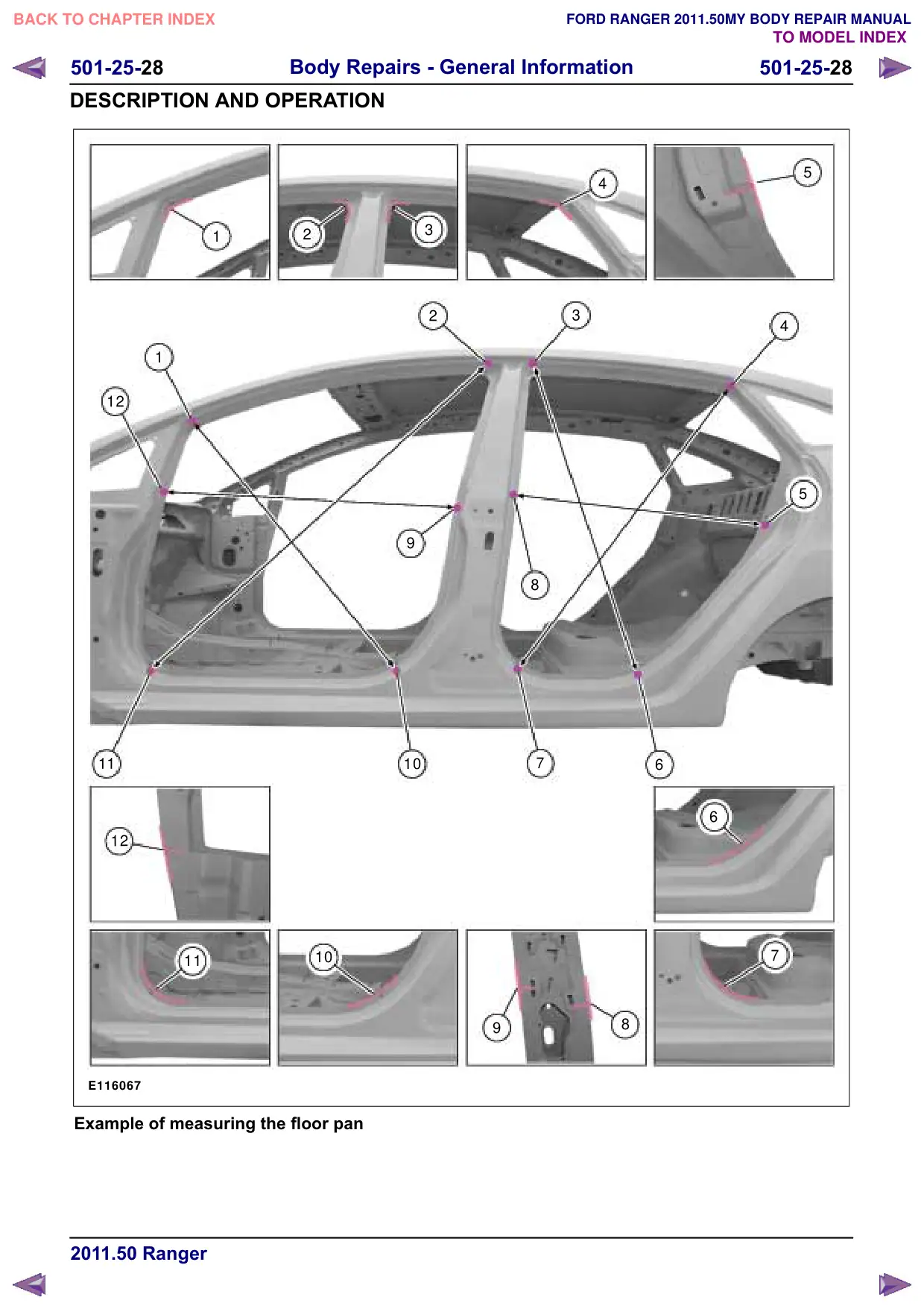
Measuring points that are specified in a curve are
to be measured so that the greatest distance from
the opposite measuring point is reflected. For exact
determination of the measuring points, enlarged
sections are shown.
Example of measuring the vehicle
superstructure
501-25-30
Body Repairs - General Information
501-25-30
DESCRIPTION AND OPERATION
Straightening
General
Straightening repairs are often required to restore
the original body shape. To do this, the vehicle
must be placed on a straightening jig so that a
pulling device can be used.
NOTE: Basic and advanced training courses are
offered for the following contents. For an overview
of all training courses offered, please refer to the
Ford Service Organisation training course
brochure.
Straightening is considered as the process of
pulling out the deformed body parts, up to cutting
out the parts that need replacing. If distorted
components remain on the vehicle, then the term
alignment work is used.
Body straightening requires practice and
experience. Before starting body straightening, the
exact direction of impact must be determined. The
straightening force must be applied in the opposite
direction to that of the impact. Only in this way can
it be guaranteed that the original shape will be
achieved again.
Note the following points during the process of
body straightening:
Secure the pulling unit with a safety cable.
Do not remove bonded glass prior to
straightening.
Never apply heat during straightening.
If necessary, open doors or hoods/lids/liftgates
during straightening.
Check dimensions and gaps continuously during
straightening.
High-strength steel panels have a stronger
tendency to retain their deformed shape.
During the straightening repairs, monitor the
attachment of the pulling unit to the vehicle.
Carry out the straightening work in several
stages, never in one pulling process. This
prevents the risk of overstretching and of joints
tearing out.
During individual straightening steps (under a
pulling load), relieve tension by striking the
deformed areas with an aluminum hammer while
they are still under tension.
Special features of non-monocoque
bodywork
Straightening is different to monocoque body
construction because of separate straightening for
bodywork and chassis.
If only the body is damaged in an accident, light
straightening repairs can be carried out while still
mounted on the chassis.
NOTE: With strong straightening forces, these
bolted connections may be damaged (bodywork
to chassis frame). Monitor the bolted connections
continuously during the straightening work. Holding
clamps or alignment angles must be attached
directly to the chassis frame.
Straightening of chassis frames
NOTE: High-strength steels must not be heated.
If the body and chassis frame have to be
straightened, they must first be separated from
each other.
The following conditions must be met:
The repair must be economically justified.
The production quality and stability of a frame
must be achieved again after carrying out the
repair.
In principle, the driving and operating safety of
the vehicle is paramount.
Cold straightening of deformed areas with sharp
edged folds cannot be carried out.
Straightening with the application of heat
(welding torch) requires much experience and
accurate knowledge of the behavior of steel
panels when heated.
The temperature and duration of application of
the heat are to be considered in particular.
Individual components of the frame, such as
cross members, brackets, etc. can be replaced.
501-25-31
Body Repairs - General Information
501-25-31
DESCRIPTION AND OPERATION
Complete Panel Replacement/Partial Replacement
NOTE: Basic and advanced training is offered for
the following contents. For an overview of all
training courses offered, please refer to the Ford
Service Organisation's training course brochure.
Repairs always mean intervention in the body shell
structure and thus also intervention in the vehicle's
passive security system.
NOTE: From an economic perspective, the
possibility of a partial replacement (sectional repair)
must be considered when assessing an
accident-damaged vehicle.
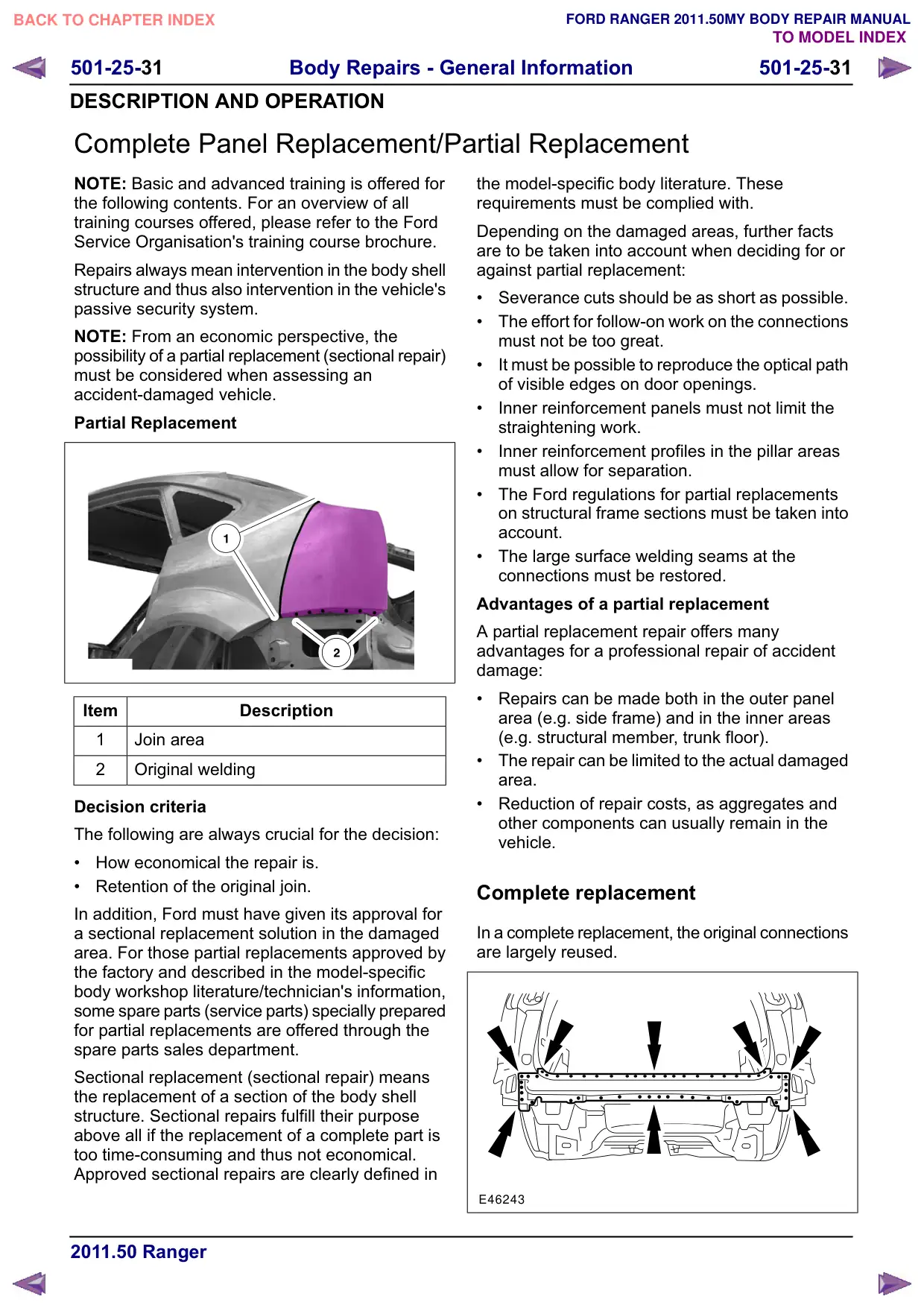
Partial Replacement
Item
Description
1
Join area
2
Original welding
Decision criteria
The following are always crucial for the decision:
How economical the repair is.
Retention of the original join.
In addition, Ford must have given its approval for
a sectional replacement solution in the damaged
area. For those partial replacements approved by
the factory and described in the model-specific
body workshop literature/technician's information,
some spare parts (service parts) specially prepared
for partial replacements are offered through the
spare parts sales department.
Sectional replacement (sectional repair) means
the replacement of a section of the body shell
structure. Sectional repairs fulfill their purpose
above all if the replacement of a complete part is
too time-consuming and thus not economical.
Approved sectional repairs are clearly defined in
the model-specific body literature. These
requirements must be complied with.
Depending on the damaged areas, further facts
are to be taken into account when deciding for or
against partial replacement:
Severance cuts should be as short as possible.
The effort for follow-on work on the connections
must not be too great.
It must be possible to reproduce the optical path
of visible edges on door openings.
Inner reinforcement panels must not limit the
straightening work.
Inner reinforcement profiles in the pillar areas
must allow for separation.
The Ford regulations for partial replacements
on structural frame sections must be taken into
account.
The large surface welding seams at the
connections must be restored.
Advantages of a partial replacement
A partial replacement repair offers many
advantages for a professional repair of accident
damage:
Repairs can be made both in the outer panel
area (e.g. side frame) and in the inner areas
(e.g. structural member, trunk floor).
The repair can be limited to the actual damaged
area.
Reduction of repair costs, as aggregates and
other components can usually remain in the
vehicle.
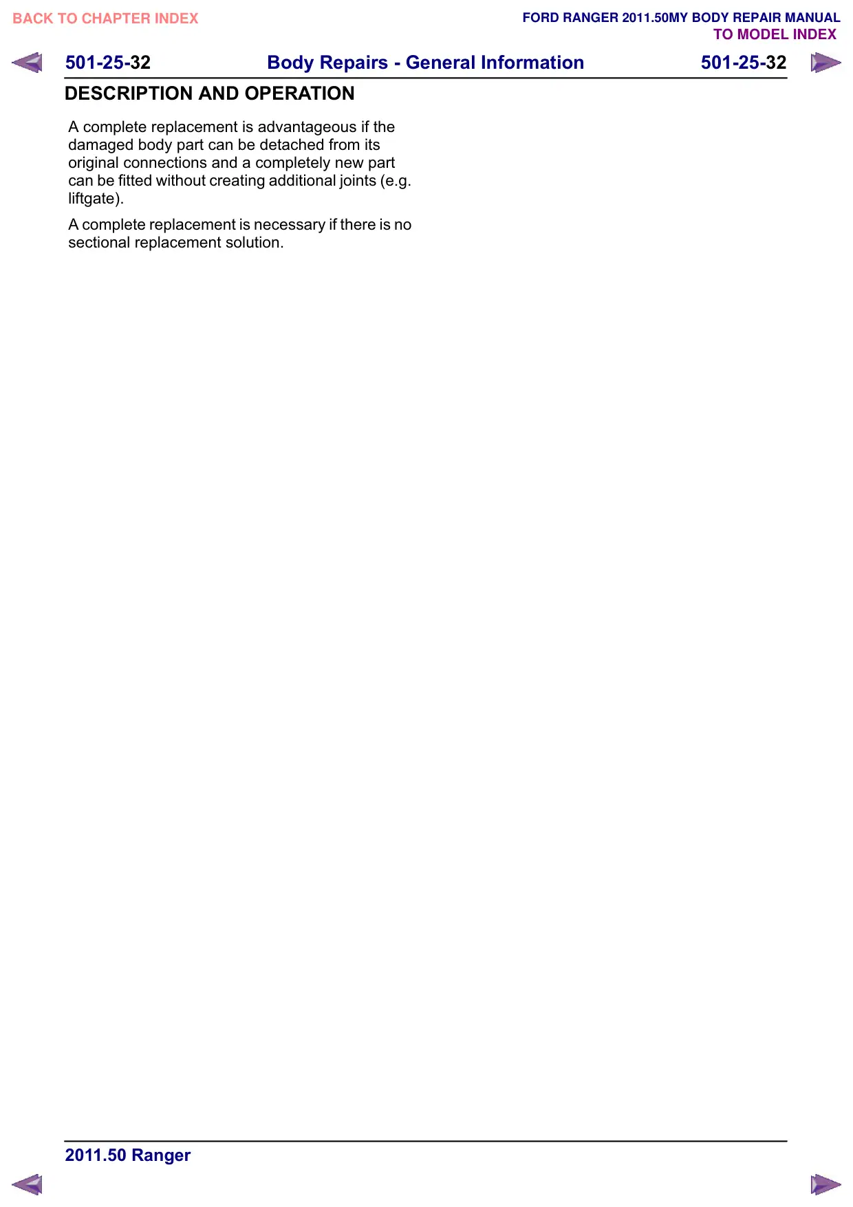
Complete replacement
In a complete replacement, the original connections
are largely reused.
E46243
501-25-32
Body Repairs - General Information
501-25-32
DESCRIPTION AND OPERATION
A complete replacement is advantageous if the
damaged body part can be detached from its
original connections and a completely new part
can be fitted without creating additional joints (e.g.
liftgate).
A complete replacement is necessary if there is no
sectional replacement solution.
501-25-33
Body Repairs - General Information
501-25-33
DESCRIPTION AND OPERATION
Corrosion Prevention
The corrosion protection provided in production
must be carefully maintained and reproduced
during body repair work, in order to ensure the
long-term warranty for Ford vehicles.
NOTE: Please take the notes in the model-specific
repair descriptions into account. Please also note
the manufacturer's instructions when handling the
different anti-corrosion agents.
Only Ford original bodywork components and Ford
approved repair materials are to be used for body
repairs. The Ford logo is stamped onto every Ford
original spare part.
Panel coatings and corrosion
protection
Body steel panels are provided with a coating for
corrosion protection purposes. The coating material
is predominantly zinc in a variety of composition
forms. Aluminum is also used to some extent.
Basically, all types of steel sheet can be coated.
A variety of coating processes are used:
Hot dip zinc coating.
Electrolytic zinc plating.
Organic coating.
Hot dip aluminum coating.
NOTE: Welding fumes are harmful to health. Make
certain that the workspace is well ventilated and
use welding fume extraction.
The following points must be noted when welding:
Zinc starts to melt at about 420°C.
The zinc vaporizes at a temperature of about
900°C.
The amount of heating determines the damage
to the zinc coating, and therefore to the
corrosion protection.
Resistance spot welding is particularly suitable
for welding zinc-coated panels, because no
widespread warming occurs.
With electrolytically zinc-plated panels there is
no need for any special preparation because
the zinc coating does not need to be removed.
NOTE: Coated panels have a higher electrical
resistance, but this can be compensated for by
increasing the welding current by 10 - 20% .
Corrosion protection measures during
repair work
CAUTION: Always be extremely careful
when handling solvents, sealants and
adhesives. Some products contain
substances harmful to health or give off
harmful or poisonous vapors. Always
follow the manufacturer's instructions. If
there is any doubt as to whether a
particular solvent is suitable, it must NOT
be used.
All Ford bodywork components have a cathodic
primer. Moreover, most parts are zinc-plated on
one or both sides. If possible, these protective
layers must not be damaged.
Before welding
Interior surfaces of new bodywork components
which will no longer be accessible after installation
must be painted beforehand. The welding flanges
are treated with a special welding primer. The joint
areas are not always accessible from inside later.
Therefore, prepare these areas so that no soot is
produced by burning paint during welding.
NOTE: In order to ensure that the corrosion
protection produced in production is not destroyed,
the working area must be kept as small as possible.
NOTE: Do not touch cleaned bare metal any more
with the bare hands. The dampness of your hands
will corrode the metal.
Procedure:
Remove the primer or paint/zinc layer in the
welding area using a tress wire brush to prevent
the formation of soot from the paint.
Thoroughly clean the welding area with a metal
cleaning agent and rub dry.
Coat the welding flange with welding primer on
all sides and allow to dry.
NOTE: The welding primer must only be applied
thinly to the spot welding area, to minimize
spattering when welding.
After welding
During repair work, body panels are often heated
at very high temperatures, which results in the
destruction of the corrosion protection.
501-25-34
Body Repairs - General Information
501-25-34
DESCRIPTION AND OPERATION
Reworking of the affected areas is therefore vital:
Grind the welded seams flat and clean
thoroughly with silicone remover. Dry with a
lint-free cloth.
If the join area is accessible from the inside, the
transition area to the paint must be abraded for
all types of join so that good adhesion of the
primer is achieved later.
If the join area is not accessible from the inside,
the cleaning and sanding work is not done. For
this reason, ensure that there is as little
contamination as possible in the area of the
repair. This allows the cavity wax applied later
to penetrate the join area without hindrance.
NOTE: Only apply a small amount of panel cleaner
to the cleaning cloth when cleaning the repair area.
Make sure that no cleaner reaches the connecting
flange, so that the welding primer is not washed
away again.
Priming after welding
Primer is applied to the welded flanges after
cleaning. A check must also be made that the
production corrosion protection is present in the
area of the flanges. Any damage must also be
re-primed.
Sealing work
If MIG welding is carried out during a sectional
repair on a connecting flange with sealant or
adhesive material, the material must be applied
at a distance of approx. 10 mm from the weld
spot.
These areas must be sealed very carefully after
the work has been completed.
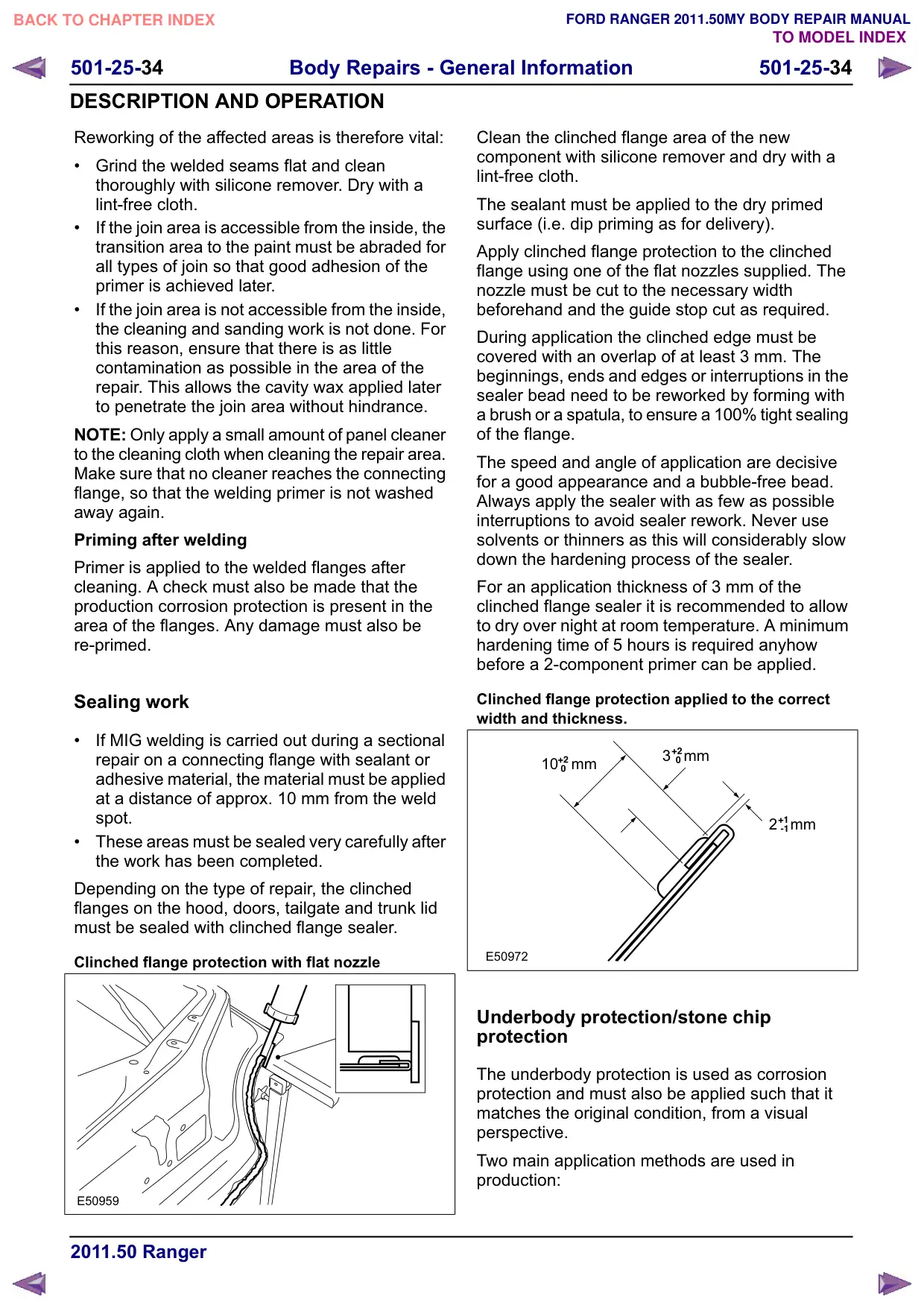
Depending on the type of repair, the clinched
flanges on the hood, doors, tailgate and trunk lid
must be sealed with clinched flange sealer.
Clinched flange protection with flat nozzle
E50959
Clean the clinched flange area of the new
component with silicone remover and dry with a
lint-free cloth.
The sealant must be applied to the dry primed
surface (i.e. dip priming as for delivery).
Apply clinched flange protection to the clinched
flange using one of the flat nozzles supplied. The
nozzle must be cut to the necessary width
beforehand and the guide stop cut as required.
During application the clinched edge must be
covered with an overlap of at least 3 mm. The
beginnings, ends and edges or interruptions in the
sealer bead need to be reworked by forming with
a brush or a spatula, to ensure a 100% tight sealing
of the flange.
The speed and angle of application are decisive
for a good appearance and a bubble-free bead.
Always apply the sealer with as few as possible
interruptions to avoid sealer rework. Never use
solvents or thinners as this will considerably slow
down the hardening process of the sealer.
For an application thickness of 3 mm of the
clinched flange sealer it is recommended to allow
to dry over night at room temperature. A minimum
hardening time of 5 hours is required anyhow
before a 2-component primer can be applied.
Clinched flange protection applied to the correct
width and thickness.
3
mm
10
mm
2
mm
E50972
Underbody protection/stone chip
protection
The underbody protection is used as corrosion
protection and must also be applied such that it
matches the original condition, from a visual
perspective.
Two main application methods are used in
production:
501-25-35
Body Repairs - General Information
501-25-35
DESCRIPTION AND OPERATION
The underbody protection is applied as a
sprayable sealing compound.
In the area around the structural members, the
underbody protection is sprayed on and spread
across a wide area.
Because of the coarse surface structure of the
stone chip protection material, it is recommended
to only perform a repair over the whole surface, if
there is damage over visible areas. Otherwise there
is the danger of serious irregularities on the
surface.
The thickness and appearance of the underbody
protection and stone chip protection must be
matched to the original. Special spray guns are
used to work the materials for this reason. A test
spray must always be performed beforehand
however, to determine the correct appearance and
layer thickness.
Cavity protection
After painting work has been completed, a general
check is made of the work that has been done.
Before final reassembly of the vehicle, the cavity
wax protection in the area of the repair must be
renewed. Cavity wax protection must be performed
carefully so that the quality of the repair conforms
with Ford standards:
Guide the cavity wax probe carefully in the area
of the repair so that targeted corrosion
protection is achieved.
Pay special attention to edges and swage line
on stepped joints, the wax must cover the inner
edge areas.
The cavity wax must flow along the stepped
sheets so that the wax is drawn between them
by capillary action.
A hole may be drilled in a suitable place for areas
which are not accessible for the application of
cavity wax. The diameter depends on the size of
plugs available. When this is done it is vital to make
sure that no drilling swarf remains in the cavity (rust
will form if any remains). The edge of the hole must
be treated with cavity wax. Finally close with a plug
and seal with underseal.
Only on components with clinched flange edges:
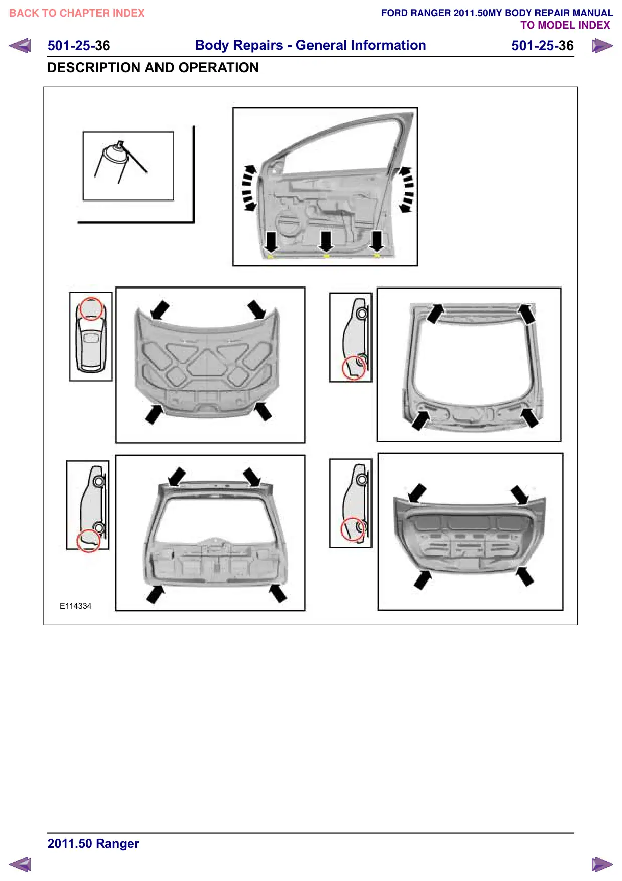
After painting, the inner clinched flange edge must
be sealed as far as is possible with cavity wax. For
this, the repaired component should be positioned
upright and corrosion protection wax sprayed into
the water drainage holes and/or the thread holes
for the hinges in both directions (50 ml corresponds
to about 20 seconds spraying time).
For doors, tilt and turn the component to spread
the corrosion protection wax over the whole edge
of the flange.
Wax application
501-25-37
Body Repairs - General Information
501-25-37
DESCRIPTION AND OPERATION
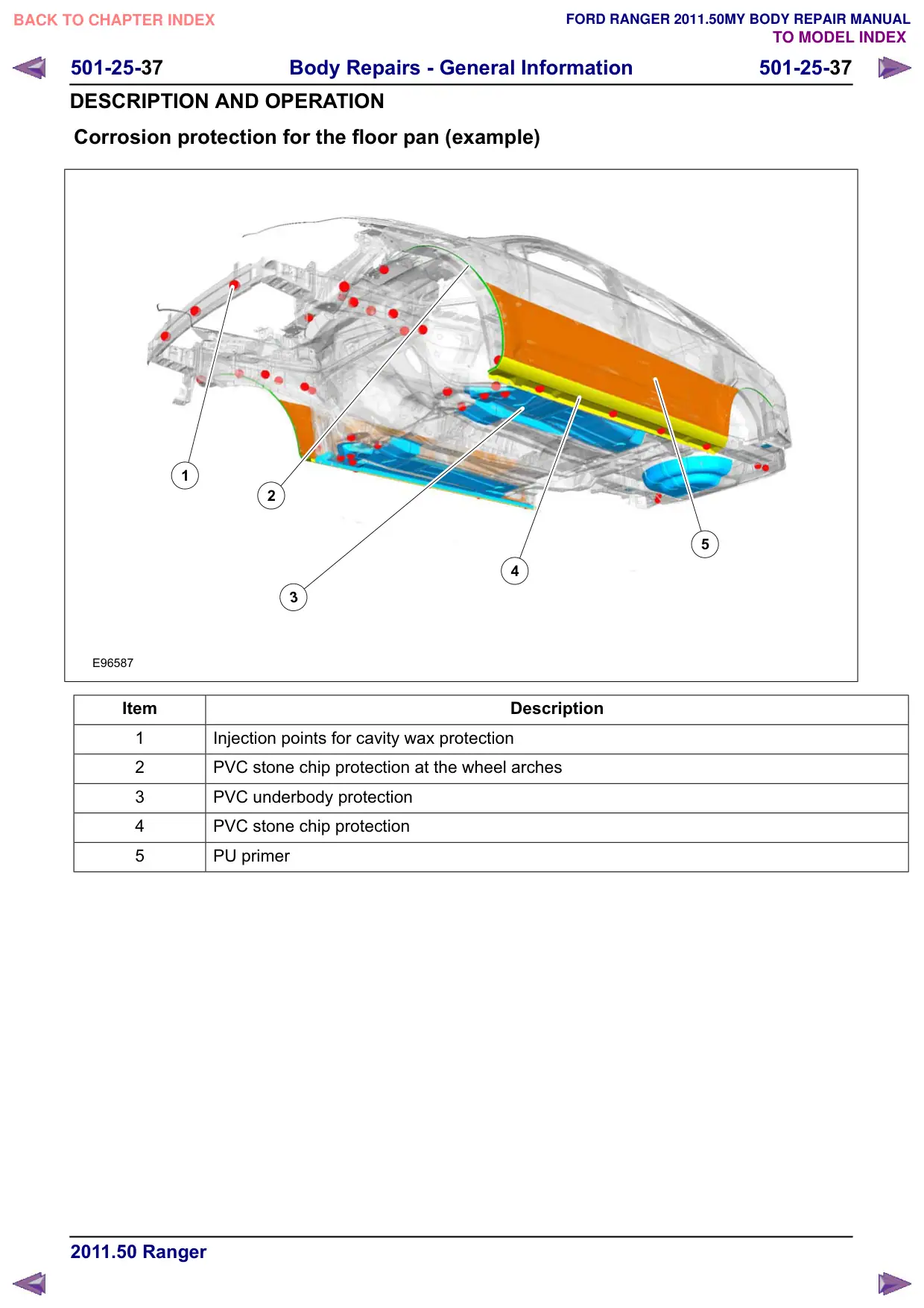
Corrosion protection for the floor pan (example)
1
1
2
2
3
3
E96587
Item
1
Injection points for cavity wax protection
2
PVC stone chip protection at the wheel arches
3
PVC underbody protection
4
PVC stone chip protection
5
PU primer
5
5
4
4
Description
501-25-38
Body Repairs - General Information
501-25-38
DESCRIPTION AND OPERATION
Corrosion Damage/Corrosion Repair
Modern vehicle bodies are protected from corrosion
by elaborate measures. Multilayer coatings on the
panel surface prevent direct contact between the
metal and oxygen, and so protect it from corrosion.
In the long-term however, corrosion on a vehicle
cannot be completely prevented.
NOTE: Basic and in-depth training is offered on
the following topics. You will find an overview of
the complete range of training in the Training
Brochure issued by the Ford Service Organization.
What is corrosion?
Corrosion is destruction of a subsurface caused
by chemical or electrochemical effects which
operate from the outer surface.
If the protective layers become damaged,
electrochemical conversion processes are initiated,
which allow the metal to oxidize. This leads to the
formation of corrosion.
The following factors lead to corrosion:
Mechanical damage such as stone chips and
scratches which penetrate through to the steel
panel.
Damp interiors.
Unfavorable weather or environmental
conditions, as may occur in areas with high
humidity, high salt content in the air or serious
air pollution due to aggressive gases and dusts.
Insufficient corrosion protection after repairs.
Lack of care by the vehicle owner of the painted
and corrosion proofed surfaces or areas on the
vehicle.
In order to maintain long-term corrosion protection,
the vehicle must be checked at regular intervals.
In doing so, the follow areas must be inspected
and any damage rectified:
Damage to the paint surface cause by scratches
or stone impact must be suitably rectified
according to the specifications.
Damage to the PVC underbody protection or
the PU stone chip protection must be refinished.
Damage to the PVC underbody protection or
the PU stone chip protection must be refinished.
Incomplete or damaged sealing at clinched
flanges must be renewed.
Check the cavity protection and renew it if
incomplete.
Poorly installed or damaged covers and stone
chip protection fixtures must always be renewed.
Check seals and seal carriers for wear and
correct mounting. Any damaged seals must be
renewed.
All rubber grommets and blanking plugs must
be present and correctly installed.
A damp or wet floor inside the vehicle indicates
that there are leaks in the bodywork. The interior
must be dried out and the leaks must be
completely rectified.
The corrosion formation can vary in extent.
With rust film or edge rust formation, the surface
of the paint has small traces of corrosion present.
The traces of corrosion can possibly be removed
in such cases by polishing the paint surfaces. If
this is not possible however, the traces of corrosion
must be rectified by using a touch-up technique.
If the corrosion is just starting, with up to 1 mm
rusting below (in the form of a dot or a line) the
damage is rectified as follows:
Clean the defective location.
Mechanically remove the rusting which is
starting below the surface.
If the area is small, apply primer and allow it to
dry, then use the paint pencil to touch up the
area - if not, respray the damaged area.
If rust is already under the paint finish to the steel
panel, then the whole paint finish in the affected
area must be sanded away.
Furthermore, the existing traces of corrosion in the
body panel must be carefully and completely
removed.
Finally a new paint finish must be applied in this
area. In the case of rusting through, the affected
body panel is already completely destroyed. Such
damage requires complete or at least partial
replacement.
NOTE: : In the general section there are several
chapters which present the techniques necessary
for a professional corrosion repair.
The outcome of this is the following repair
sequence:
Remove the rusted-through part.
Remove the remaining traces of corrosion.
Offer up the new part.
Prepare the joint areas.
501-25-39
Body Repairs - General Information
501-25-39
DESCRIPTION AND OPERATION
Weld the new part into place.
Produce the corrosion protection.
For a professional repair it is essential to reproduce
the corrosion protection during and after the repair.
501-25-40
Body Repairs - General Information
501-25-40
DESCRIPTION AND OPERATION
Sealer, Underbody Protection Material and Adhesives
Sealants, adhesives, cavity wax and underbody
protection materials are used during the various
body repairs. In this area Ford offers a range of
products which have been tested and matched to
each other.
CAUTION: Always be extremely careful
when handling solvents, sealants and
adhesives. Some products contain
substances harmful to health or give off
harmful or poisonous vapors. Always
follow the manufacturer's instructions. If
there is any doubt as to whether a
particular solvent is suitable, it must NOT
be used.
Clinched flange protection
One-component adhesive/sealer which can be
applied by brush or spraying, based on MS
polymer, with a flat nozzle for application and with
the following properties:
Can be sanded
Permanently elastic
Non-corrosive
Very good adhesion
Rapid hardening and resistant to ageing
Can be over-painted with almost all proprietary
paints
Seam sealant T Anthracite
One-component sealer based on MS polymer, for
sealing joints and seams, with the following
properties:
Silicon-free
Solvent-free and low-odor
suitable for gluing HVH elements into position
in their respective body areas
Body sealant T beige
Sealer with the following properties:
Stable
Contains solvent
Especially suitable for visible seams
After hardening can be overpainted with
two-pack paint
Underbody Coating
Underbody protection is necessary for permanently
elastic corrosion protection of vehicle underbodies.
It is very durable and has good resistance to
abrasion,
Cavity wax
This touch-proof, transparent corrosion protection
wax is used for the preservation of cavities and
flange joints.
Anti-corrosion wax
Anti-corrosion wax is a coating material which can
be applied in fine spray, forming a very thin and
grease-like protective film, therefore offering very
good corrosion protection.
2-component metal adhesive
For joining metal to metal and plastic to metal. The
adhesive reduces droning noises and improves
corrosion protection.
Windshield sealant
Solvent-containing, stable sealing material. The
sealer is permanently elastic and does not form a
skin on the surface.
1-component window glass adhesive kit
For direct glazing. The vehicle is ready to drive
after 6 hours (passenger airbag). Prevents contact
corrosion.
2-component window glass adhesive kit
For direct glazing. The vehicle is ready to drive
after 1 hour (passenger airbag). The adhesive is
not an electrical conductor and permits
interference-free radio reception. Prevents contact
corrosion. Using a 150ml additional cartridge, the
adhesive can also be used for large windows or to
produce a double seam of adhesive.
PU glass adhesive
150ml additional/replacement cartridge for direct
glazing using 2-component window adhesive kit.
Suitable for double beads or larger windows. Also
suitable for sealing NVH elements.
501-25-41
Body Repairs - General Information
501-25-41
DESCRIPTION AND OPERATION
Cutting Technique
NOTE: Without exception, before starting work you
must read the safety and warning instructions in
the chapter "Safety Instructions". In addition, pay
attention to the warning instructions of the particular
equipment manufacturer.
Possible cut lines (example)
E112277
Depending on the separating tools used, there are
some fundamental points to bear in mind:
Only start the cutting work once the new part is
to hand.
Compare the new part with the old part for
shape and size.
The straightening work must be completed
before any body components to be replaced are
cut out.
Before separation work is started, all welded
connections which cannot be seen must be
freed of underbody protection, sealant etc.
Spot weld milling tool
Resistance spot welds are separated using a spot
weld drilling machine or a spot weld milling tool.
NOTE: After all separation work, make certain that
the metal swarf is completely removed from the
vehicle body.
450 mm
E58855
NOTE: Steplessly variable machines increase the
working life of the cutting tool. Use of a suitable
lubricant can increase this even further.
A spot weld milling tool usually has an adjustable
depth stop and a safety fixing system. These
prevent the machine from drilling too deep and the
cutter from slipping while working.
501-25-42
Body Repairs - General Information
501-25-42
DESCRIPTION AND OPERATION
Rod sander
Another option for separating resistance spot welds
is to use the rod sander.
TO BE UPDATED LATER
If spot welds and MIG welds are difficult to reach,
a rod sander may offer an alternative.
Short stroke saw
The short stroke saw is suitable for separating
vehicle body components and for making a
separating cut for partial repairs.
TO BE UPDATED LATER
NOTE: In order not to damage panels, wiring
harnesses, hoses or similar components which lie
behind, remove them beforehand as necessary.
The narrow design of the saw blade permits cutting
in tight curves. Straight cuts require a relatively
great deal of practice.
Orbital saw
Where use of the short stroke saw is difficult
because of the body construction, the orbital saw
can be used.
TO BE UPDATED LATER
The cutting depth of the orbital saw can be set.
This allows separating cuts to be made, despite
panels or other components lying in danger behind.
Straight cut lines can be more easily made using
the orbital saw.
501-25-43
Body Repairs - General Information
501-25-43
DESCRIPTION AND OPERATION
Panel Beating Technique and Smart Repairs
General
Smaller scale body repairs, where damaged panels
do not need to be replaced, can often be carried
out by realignment work. Whether the repair is
economical however, often depends on the
accessibility of the affected body area.
NOTE: Basic and in-depth training courses are
offered on the topics which follow. An overview of
the complete range of training offered is provided
by the Ford Service Organization Training
brochure.
During damage assessment, the following technical
points must be taken into account:
Small mild dents (without damage to the paint),
which are in areas that make access from the
inside possible, can be rectified using
undamaged paint panel beating.
If the inner side of the damaged area (with paint
damage) can be accessed, then conventional
panel beating techniques can be used.
If the damaged area has no access from inside,
then it can only be rectified using outside panel
beating techniques.
Dent removal using special panel
beating levers
NOTE: In the Undamaged Paint Dent Removal
section, you will find more information on pressure
techniques.
TO BE UPDATED LATER
Des
Description
FULSW
ion
1
Deflection by a hook arrangement
2
Pressure tool
This panel beating technique with pressure is
mainly used to rectify smaller dents as a result of
hail impact, transportation or parking, without the
paint being damaged.
Small dents are removed from the inside of the
body panel by pushing them outwards in a
mechanical process using panel beating levers.
Because of the great variety of shapes of these
levers, it is possible to use this panel beating
technique on almost all areas of the vehicle body.
501-25-44
Body Repairs - General Information
501-25-44
DESCRIPTION AND OPERATION
Dynamic puller with counter bearing
E122695
Des
Description
FULSW
ion
1
Puller device for minor damage, with
integral copper electrode
2
Puller device for more extensive damage
3
U-washers spot-welded in place
4
Puller bits spot-welded in place
5
Attachment for U-washers or puller bits
This method can be used to reshape dents or more
extensive damage from the outside.
For minor damage, the copper electrode in the tool
is secured onto the panel surface by spot-welding
and the puller device is used to pull out the damage
without jolting.
For more extensive damage, puller bits or
U-washers (depending on the application area) are
spot-welded to the panel surface and the area
pulled out using the puller device.
Because of the versatile puller and the variable
counter bearing, a wide variety of damage can be
worked and rectified using this repair method.
Because of the mechanical lever operation, the
variable counter bearing and the optimum
controlled application of power, this external dent
removal system allows dents in almost all vehicle
body areas to be pulled out.
Hollow leveling (removing dent without
a dolly)
Hollow leveling can only be used on areas which
are accessible from the rear.
TO BE UPDATED LATER
501-25-45
Body Repairs - General Information
501-25-45
DESCRIPTION AND OPERATION
Des
Description
FULSW
ion
1
Center of dent
2
Spoon
During hollow leveling, the dent is removed from
the inside a using suitable panel beating tool and
applying knocking or pressing movements. High
spots around the edge of the dent area are
flattened with blows from the aluminum or wooden
headed hammer.
The usual tools are for instance hammers of
various designs, dollies, levering irons and various
spoon irons. The correct choice of tool is made
depending on the shape of the dent and the access
which is possible.
Dent removal using hammer and dolly
Panel beating can only be performed using a
hammer and dolly if access can be gained from
the rear side.
TO BE UPDATED LATER
Des
Description
FULSW
ion
1
Aluminum hammer
2
Box file
The purpose of the dolly in this case is to transfer
the force of the impacts from the hammer to the
steel panel which is in between. As this is done,
the deformed body panel is smoothed (dressed)
and the tension fields in the body panel are
removed.
The favored tool for this repair process is the
aluminum hammer and as opposite support the
universal hand dolly. To rectify minor panel
damage, the box file should be used as opposite
support. Because of its serrated surface, the box
file prevents normal stretching of the body panel
which would otherwise occur.
Heat-induced material shrinking
Material shrinking, also called settling in, can be
performed in a variety of ways depending on the
extent of the damage and the access to the repair
area.
These repair processes differ depending on the
type of heating and subsequent working of the
heated surface. They sub-divide into two basic
processes:
Heating using a carbon electrode.
Heating using the oxy-acetylene torch.
In the carbon electrode process the working is done
exclusively by warming. In this case the access to
the repair position is only from the outside.
TO BE UPDATED LATER
Des
Description
FULSW
ion
1
Carbon electrode
501-25-46
Body Repairs - General Information
501-25-46
DESCRIPTION AND OPERATION
Des
Description
FULSW
ion
2
Spiral shaped heating pattern
If the damage is concentrated in a spot and is in
the form of a more rigid raised area, then the
carbon electrode must be replaced by a copper
electrode. As heat is applied, slightly more pressure
is applied to the raised area.
In the method using heating by the oxy-acetylene
torch, material shrinking is achieved by a
combination of heat and mechanical working of the
damaged area.
TO BE UPDATED LATER
Des
Description
FULSW
ion
1
Overstretched area
2
Point heating using the oxy-acetylene
torch
3
Spiral shaped knocking back with dolly
The repair area must always be accessible from
both sides, so that the heated area can be properly
worked mechanically.
The combination of heating and mechanical
working is very effective.
As soon as the warm point is established,
hammering is immediately started using the
aluminum hammer together with a suitable dolly
on the inside of the repair surface, working in spiral
movements towards the warm point. This causes
material to build up in the center of the warmed
area.
Lead loading
Despite good external panel beating techniques,
it is not always possible to rectify every surface
unevenness. For this reason, application of lead
loading is an important part of panel beating.
CAUTION: Poisonous gases and dust can
be produced when working solder. Use an
extraction unit and, if required, a protective
mask.
NOTE: Since 07/2003, lead compounds have been
ruled out for production. Appropriate lead-free tin
solders and pastes must also be used in the
workshop.
Typical application areas:
Body components with limited or no access from
the rear.
Body components with very narrow
cross-section.
Body components which are particularly
exposed or which can move.
Weld seams of partial repairs.
Rocker panel areas, wheel arch edges, side
panel areas.
Doors, hood, luggage compartment lid.
Swage lines and joint areas.
Tin has the following advantages:
Excellent bonding on bare metal surfaces.
Good moulding properties.
Good properties for the production of shapes
and contours.
Permanent shape.
Heat expansion is the same as steel.
To create a basis for the actual lead loading
process, a lead loading paste is first applied to the
panel. The paste is then heated and wiped away
with a cloth. Now the tin can be applied and
moulded with a brazing block.
501-25-47
Body Repairs - General Information
501-25-47
DESCRIPTION AND OPERATION
After the repair site has cooled down, it is worked
using for example the body plane until the surface
is smooth and has no transitions.
501-25-48
Body Repairs - General Information
501-25-48
DESCRIPTION AND OPERATION
Paintless Dent Removal
NOTE: Basic and in-depth training is offered on
the following topics. You will find an overview of
the complete range listed in the Training brochure
published by the Ford Service Organization.
General
Application is restricted to body surfaces which are
accessible from both sides. This repair technique
is seldom feasible on double-skinned body
components or closed body profiles. The same
applies to edge areas, swage lines and seams on
body components, which are very dimensionally
stable.
The following characteristics must be present for
a dent to be removed:
The diameter must be no more than 50 mm.
No material stretching in the centre of the dent.
Repair area must be accessible
Furthermore, sufficient experience in the use of
special tools and knowledge of materials are also
requirements for a successful repair.
TO BE UPDATED LATER
Item
Description
1
Deflection by a hook arrangement
2
Pressure tool
Mild dent
TO BE UPDATED LATER
Satisfactory repair results are only possible on mild
dents with little depth and small deformation radii.
Therefore this repair method is particularly suitable
for hail, parking and transportation damage.
Dent with material stretching
501-25-49
Body Repairs - General Information
501-25-49
DESCRIPTION AND OPERATION
TO BE UPDATED LATER
If strong and direct force during the damage
process causes the material to stretch in the middle
of a dent, then the result is a small and sharp
edged dent. Such damage cannot be rectified
without visible deformation.
Advantages of a planishing technique:
Economical in time and materials
The original paint is retained
Environmentally friendly (no sanding or painting
work)
While carrying out the repair, the following itemized
repair route and process flow must be complied
with:
1. Damage diagnosis
2. Repair preparations
3. Perform repair
4. Paint finishing, corrosion protection and quality
control
In order to ensure corrosion protection, all inner
areas of the repair must be treated afterwards.
Where it is possible, the paint is repaired. In every
case the inner area of the repair must be treated
with cavity wax.
501-25-50
Body Repairs - General Information
501-25-50
DESCRIPTION AND OPERATION
Plastic Repairs
General
The proportion of plastics used in vehicle
construction continues to rise. Up to now damaged
plastic components often had to be replaced.
These days, plastic repairs are becoming more
and more widely accepted because of the
increasing cost of spare parts.
NOTE: Plastic adhesives are chemical products
and are subject to the safety instructions of the
manufacturer.
In repair work, the material properties of plastics
are highly significant. There are two main groups:
Thermoplastics.
Thermosets.
NOTE: Elastomers make up a third group of
plastics. These are not mentioned below because
they have no plastics repair applications.
Thermoplastics
Heat causes thermoplastics (also called TP
polymers) to transform from the solid state into the
thermoelastic state and then into the thermoplastic
state. When thermoplastics are cooled, they return
to solid state.
Brief
Plastic
descrip-
WLRQ
ABS
Acrylonitrile butadiene styrene
copolymer
PA
Polyamide
3&
Polycarbonate
33
Polypropylene
PP/EPDM
Polypropylene/ethylene propylene
diene copolymer
PC/PBT
Polycarbonate/polybutylene tereph-
WKDODWH
Hard PVC
Polyvinylchloride
/ soft PVC
Thermosets
Thermosets (also called TS polymers) are much
harder and more brittle than thermoplastics. Their
strength remains largely unchanged when they are
heated. Thermosets are destroyed when heated
above the critical temperature. Also, the original
state will no longer be restored on cooling.
Brief
Plastic
descrip-
WLRQ
*53
Glass reinforced plastic
385
Close-meshed cross-linked poly-
urethane
385
Wide-meshed cross-linked poly-
urethane
Plastic identification
Normally the appropriate identifier is marked on
the plastic components used in vehicle
construction.
The capital letter sequences used for this are
standardized in DIN EN ISO 1043-1 and DIN ISO
1629 (for rubber) and can be looked up in the
tables which they contain. In addition the string of
characters provides information about the exact
mixture ratio and the proportion of certain fillers.
Examples of the identification of plastics
E122806
501-25-51
Body Repairs - General Information
501-25-51
DESCRIPTION AND OPERATION
E122807
E122808
NOTE: The identification of the type of plastic is
necessary for the plastic welding process in order
to determine the correct welding rod (welding
material) to use.
If an identifier is missing or cannot be made out,
the following easy to perform tests will help:
Visual Inspection
Visual inspections mainly serve to identify PUR
and GRP materials. Thermoplastic components
are often painted and are therefore difficult to
identify.
Identification characteristics:
When PUR cracks or similar damage occurs,
pores of foam can be seen.
GRP can be recognized by the glass fiber
structure on the inside.
Mechanical test:
The plastic group can be determined by a sound
test:
Degree of hardness - the higher-pitched the
sound, the harder the plastic.
Elasticity - the more muffled the sound, the
higher the elasticity of the plastic.
Sanding test
In this a place is chosen which will not be visible
later, and the finger belt sander is used to sand the
plastic.
The plastic group can be determined using the
pattern of the dust:
Thermosets produce a white dust.
Thermoplastics smear and do not produce dust.
Float test in water:
Take a small piece of plastic from the component
to be repaired and test whether it floats on water
(PP-EPDM, HD-PE, PP) or sinks (PVC/U, PVC/P,
ABC, PC).
Nature of the surface
The surface of plastics can be categorized as rigid
(PVC-U, PVC-P) and waxy (PP/EPDM, HD/PE,
PP).
Adherence test using welding rod
Heat a welding rod that is identified with the type
of material and the plastic component using the
hot air gun. Press the welding rod onto the plastic
component to be welded. When the welding rod
cools down, if it remains stuck to the component
or can only be removed with great difficulty, then
it can be assumed that the two are made of the
same plastic. When pulling away from PP/EPDM,
HD/PE and PP, this can lead to strings.
CAUTION: Danger of poisoning! When
burned, most plastics release vapors
harmful to health. Ventilate the room well
and use respiratory protection. Where
possible work using an extraction system.
Burning test
Every plastic has a characteristic behavior and
smell when burned. Using a knife, cut off a small
piece from the component to be repaired, remove
any dirt and paint residues and set light to the small
chip. Now observe the burning behavior. Compare
the color, type and smell of the smoke with the
results from the following table.
Short
Plastic recognition using a
descrip-
burning test
WLRQ
ABS
Blackish smoke, the material drips
like a candle when burning and
smells like wax.
PA
No smoke, draws filaments, smells
like burnt horn.
501-25-52
Body Repairs - General Information
501-25-52
DESCRIPTION AND OPERATION
Short
Plastic recognition using a
descrip-
burning test
WLRQ
3&
Yellowish, sooty smoke. Smells
sweetish.
33
No smoke, the material drips like a
candle when burning and smells like
burnt oil.
PP/EDM
No smoke, the material drips like a
candle when burning and smells like
burnt oil.
PC/PBT
Hard and shiny, burns yellow, fluffy
soot.
Hard PVC
Blackish smoke and acrid smell.
/ soft PVC
Safety instructions
In addition to the general safety instructions, the
relevant regulations and accident prevention
legislation must be observed.
NOTE: Without exception, before starting work you
must read the safety and warning instructions in
the chapter "Safety Instructions". In addition, pay
attention to the warning instructions of the particular
equipment manufacturer.
Information sheets, safety notices and guidelines
for the processing of adhesives containing
isocyanate, polyester resin, adhesives, solvent and
thinners provide more details on their use.
The following instructions must always be followed:
Polyester resin, adhesive, solvents and thinners
are inflammable and must not be used near
naked fire or flames.
Sawing and grinding operations must only be
carried out in rooms equipped with extraction
systems.
If no rooms with extraction systems are
available, only use tools with extraction
equipment.
Protective equipment such as gloves, protective
goggles, aprons and breathing masks are
essential.
Because of the various compositions of plastics,
repair work to plastic parts involves a variety of
repair methods.
The following methods are used:
Thermoplastic straightening.
Plastic welding.
Plastic adhesive bonding.
Plastic lamination techniques.
Thermoplastic straightening
Damage to thermoplastics can be rectified by
heating using the hot air gun (temperature about
100°C) while the deformation is pressed out until
the shape is regained.
Plastic welding
Splits formed in plastic bumpers are typical
possible plastic repairs.
NOTE: Do not carry out plastic welding in the area
of fixed foam backing. The foam backing will
usually be destroyed and the function of the
component is then no longer guaranteed.
If repair using adhesive methods is not possible
because of unfavorable conditions at the rear of
the repair location, plastic welding is a possible
repair process.
There are two methods of welding: hot air draw
welding and hot air fanning welding.
Plastic welding set
TO BE UPDATED LATER
Item
Description
1
Various welding rods
2
Scraper (heart-shaped)
3
Hot air blower (approx. 1500 W)
4
Clamps
5
Welding nozzles
In addition to the components listed, plastic welding
requires tools already found in the workshop such
as scrapers, sanders, face cutters etc.
501-25-53
Body Repairs - General Information
501-25-53
DESCRIPTION AND OPERATION
As with all other welding processes, only certain
material combinations can be joined together using
plastic welding.
NOTE: Basic and in-depth training is offered on
the following topics. You will find an overview of
the complete range listed in the Training brochure
published by the Ford Service Organization.
NOTE: The manufacturer's data must be taken into
account when choosing welding materials and the
correct temperature setting of the hot air gun.
Repair sequence during plastic welding:
To prepare the location for welding, remove
paint residues and sand the weld area.
If parts of the material have been pushed in by
an impact, the damaged area can be brought
back to shape by heating.
Drill out the ends of the split to stop it spreading
further. Machine the location of the weld into a
90° V-shaped groove, to accept the welding rod.
Lay the welding rod in the groove.
Perform the welding. Hot air draw welding or
hot air fanning welding.
Rework the weld seam. After cooling, sand the
raised weld seam.
Clean the sanded repair surface using plastic
cleaner. Apply plastic primer thinly to the repair
surface and paint it.
Despite good preparation and the correct choice
of welding materials, weld faults may occur.
The following points must be noted when welding
plastic:
Weld together like with like:
œ With very few exceptions, only the same
materials can be welded together, e.g. PP
with PP.
Correct temperature:
œ The correct choice of temperature is
important for the success of the repair. The
plastic must be warmed until it plasticizes
(dough-like, soft).
Guideline values for welding temperature:
Brief
Plastic
Temperat
descrip-
ure
WLRQ
ABS
Acrylonitrile butadiene
360°
styrene copolymer
PA
Polyamide
400°
Brief
Plastic
Temperat
descrip-
ure
WLRQ
3&
Polycarbonate
370°
33
Polypropylene
280°
PP/EPDM
Polypropylene/ethylene
280°
propylene diene
copolymer
385
Polyurethane
300°
Hard PVC
Polyvinylchloride
340°
Soft PVC
Polyvinylchloride
370°
Even pressure:
œ When rod welding, the pressure is applied
by pressing on the welding rod.
Steady speed:
œ To achieve a good weld, care must be taken
that the working speed is steady.
Possible causes of weld faults:
Deformation caused by overheating of the repair
area or tensions in the material while welding
the component.
Plastic material too thin.
Poor weld joint because the weld temperature
was too low or the welding speed was too fast.
Welding different materials together.
Weld seam dropped because the split gap was
too wide or the welding temperature was too
high.
A good weld is recognized by a slightly raised,
smooth and even weld bead on the surface of the
component.
The weld bead must only be worked once it has
fully cooled down.
Plastic adhesive bonding
Adhesive bonding of plastics has some advantages
over welding methods:
Within the group of thermoelastic plastics, all
semi-rigid ancillary components (such as
bumpers, front grilles, etc.) can be repaired
without identification.
A two-component polyurethane based adhesive
is used for all thermoplastic parts.
Reinforcement strips can be attached behind
splits (split length up to max. 100mm) and
501-25-54
Body Repairs - General Information
501-25-54
DESCRIPTION AND OPERATION
openings to ensure the original strength
properties.
Tools and equipment also familiar from paint
repairs can be used in making adhesive repairs to
thermoplastic components.
Angle grinders and belt sanders can be used to
grind out scratches and splits. Orbital sanders with
extractors are used for fine sanding.
The infrared heater is used to provide fast and
certain drying throughout.
Plastic adhesive set
TO BE UPDATED LATER
Item
Description
1
2-component adhesive
2
Cartridge gun
3
Mixing tube
Apart from the components shown, other materials
may be needed to bond plastics, depending on the
repair position.
For large scale repairs, it may be necessary to
insert reinforcement panel strips and reinforcement
matting as fixing aids.
Repair sequence during plastic adhesive bonding:
NOTE: Follow the manufacturer's guidelines when
using adhesives.
Prepare the location of the bond. Remove paint
residues and sand the area to be bonded. Drill
out the ends of the split to stop it spreading
further. Prepare the bond location into a
V-shape and clean it with plastic cleaner.
Apply the adhesive. The two-component
adhesive is applied to the cleaned and primed
repair location using a hand gun. Spread and
smooth the adhesive using a flexible plastic
spatula.
Rework the bond location. After cooling, sand
the raised adhesive. Clean the sanded repair
surface using plastic cleaner. Apply plastic
primer thinly to the repair surface. Apply paint.
GRP repairs
GRP material is hard and brittle in its strength
properties. Because of these material properties,
splits and openings often result in cases of serious
damage.
The stability of GRP parts is impaired if the glass
fiber reinforcement is cracked. The component
must be replaced in cases of serious damage that
affect the structure.
Minor damage (such as abrasion, splits up to
80mm, holes up to approx. 60mm diameter, etc.)
can be repaired to a technically and visually perfect
standard, provided that the damage does not occur
in heavily used or hard-to-reach areas.
To ensure perfect repair results, observe the
following points:
The room temperature should be at least 15°C
and the air should be as dry as possible.
The repair location must be thoroughly dry and
clean.
Before the repair, the GRP part being repaired
must be dried using an infrared heater or in a
drying oven.
In cases of large splits and fractures, the
strength of the outer skin can be re-established
by backing with a reinforcement material.
Tools and equipment from the paint shop can be
used to carry out repairs to GRP parts. Angle
grinders and belt sanders can be used to grind out
scratches and splits. Orbital sanders with extractors
are used for fine sanding.
GRP repair set
TO BE UPDATED LATER
501-25-55
Body Repairs - General Information
501-25-55
DESCRIPTION AND OPERATION
Item
Description
1
Polyester resin
2
Glass fiber mats
3
Hardener
Scissors, paintbrush and cleaning materials are
other materials which will be needed to perform a
GRP repair.
NOTE: Follow the manufacturer's instructions when
using the repair materials.
The repair process for a GRP repair is as follows:
Prepare the repair location. Remove paint
residues and sand the repair area.
Drill out the ends of the split to stop it spreading
further.
The repair location must be sanded by hand. If
machine working is attempted, the resin will be
heated so much that the surface structure will
be changed. The result is inadequate adhesion.
Perform the GRP repair. Apply polyester resin
thinly to the repair location. Lay the glass fiber
mat in place and apply polyester resin over it
again.
Rework the location of the repair. Sand away
any polyester resin which stands proud after it
has hardened.
Clean the sanded repair surface using plastic
cleaner. Apply plastic primer thinly to the repair
surface and after it has dried apply the paint
finish.
501-25-56
Body Repairs - General Information
501-25-56
DESCRIPTION AND OPERATION
Special Repair Techniques
Cabriolet vehicles
The body of a cabriolet vehicle is different to the
self-supporting body of a saloon car because of
E50039
These are for instance:
Longitudinal and torsional reinforcing
components which compensate for the lack of
the roof.
Reinforcements to the floor assembly,
particularly in the rocker panel area.
Reinforcements in the pillar areas.
High-strength and ultra-high-strength steel
panels with single panel thicknesses of up to
2.5 mm, which in combination can become up
to 6mm thick (e.g. reinforcements in the floor
area, rocker panels).
If deformation to load carrying components occurs,
the stability of the whole body shell can be
adversely affected.
On a cabriolet, accident damage repair to the
components mentioned above is considerably
different in certain aspects compared with the usual
repairs (closed body construction):
the special roof construction (folding top). The
stability requirements must therefore be ensured
by construction changes within the body structure.
A model specific alignment angle system must
always be used during straightening and repair
work, securing using clamps at the rocker panel
area is not always adequate for the cabriolet.
To avoid damage to the doors, they must always
be open during straightening work. In the case
of more severe damage, additional tension and
compression spindles must be used to stabilize
the door cut-outs (between the A- and B-pillars).
In load bearing areas such as the rocker panels,
side members and floor pan, increased
straightening forces are necessary due to the
additional reinforcements.
501-25-57
Body Repairs - General Information
501-25-57
DESCRIPTION AND OPERATION
NOTE: Additional information on welding can
be found in the section Welding Equipment and
Joining Techniques.
High-power welding equipment for panel
thicknesses in overall combination of up to 6
mm total material thickness.
The fitting accuracy and longitudinal rigidity of
the affected component is especially important
to ensure that the doors, door windows and the
roof fit and close correctly.
Liquefied gas vehicles
Alternative fuel vehicles often require special
handling in the workshop area. Above all, assembly
operations to some extent require particular
knowledge when dealing with the special
technology and the safety regulations.
NOTE: Only fully trained personnel are permitted
to work on alternative fuel vehicles.
These special requirements must be understood
and taken into account in the body shop as well.
CAUTION: Danger of fire and explosion.
The safety instructions must always be
followed when performing service work on
fuel/gas systems. Failure to follow these
instructions may result in personal injury.
NOTE: You will find further information about
working on liquefied gas vehicles in the section
Health and Safety Information.
Refrigerated conversion vehicles
Apart from the special materials used in building
the structure of the refrigerated compartment, such
vehicles have special energy and refrigeration
systems which require special handling during
repair.
CAUTION: Danger of injury. Work on the
230<SP>volt system of the refrigeration
equipment must only be carried out by
trained specialist personnel.
NOTE: Work on the refrigerant circuit may only be
performed by persons who have a relevant
certificate of competence.
Vehicles with a refrigerated compartment are often
used to transport foodstuffs. For this reason,
additional hygiene regulations must be complied
with during repair work.
Aluminum and plastic are used to construct the
two different types of compartment found on
refrigerated vehicles.
The aluminum conversion is a very stable and
technically perfect variant. However, against this
the relatively high production costs and a lower
payload must be taken into account, because of
the weight of the aluminum conversion itself.
NOTE: Basic and in-depth training is offered on
the following topics. You will find an overview of
the complete range listed in the Training brochure
published by the Ford Service Organization.
The plastic conversion has developed into a light,
clean and economical alternative because of
constant further development of materials and
working techniques.
NOTE: The material combinations, the
workmanship and the working methods must
comply with the current food hygiene regulations.
For this reason, service and repair work on the
refrigerated conversion may only be performed by
authorized and specially trained technicians.
Refrigerated compartment constructions are often
made using both materials. The floor pan is made
of structured, slip-proof aluminum panels and the
wall and ceiling cladding is made of smooth
surfaced plastic elements.
CAUTION: PUR hard foam is flammable. If
PUR hard foam is overheated, it will burn
on its own with a brilliant yellowish flame.
It produces unpleasant choking and toxic
fumes. Special measures must be taken
when welding the vehicle body.
Polyurethane wall and ceiling elements are
manufactured using a sandwich principle. An
insulating polyurethane core is coated with food
grade ABS plastic on one side.
PUR hard foam does not decompose, is rot
resistant and is odorless. These properties make
it suitable for use as insulation.
Because of its closed cell structure, water uptake
by PUR hard foam is for the most part only a
problem at edges. Cut edges or other mechanically
worked surfaces must however be sealed with the
greatest care.
The conversion to a refrigerated vehicle is
performed as made-to-order production. The large
surfaces of the wall and ceiling cladding can be
changed and are particularly easy to repair.
If access to the back of a body panel section is
needed because of body straightening work, in
501-25-58
Body Repairs - General Information
501-25-58
DESCRIPTION AND OPERATION
some circumstances it is cheaper to perform a
cut-out repair instead of removing an element.
The repair process is fully described in the Student
Information booklet Refrigeration System
Technology, Transit 2000.5 Freshline.
NOTE: You will find further information about
working on vehicles with a refrigerated
compartment in the section Health and Safety
Information.
501-25-59
Body Repairs - General Information
501-25-59
DESCRIPTION AND OPERATION
Joining Techniques
Welding
Before welding work is performed on a vehicle
body, all safety measures for the protection of
people, modules and electrical components must
be observed.
NOTE: Before beginning the work, please refer to
the safety instructions and warnings in the chapter
Safety Instructions. Please also note the warnings
of the respective equipment manufacturer.
E113734
In doing so, the repair welds must match the
standard of those produced in production in number
and diameter.
Preconditions for resistance spot welding:
The panels to be welded overlap.
The weld spot is accessible on both sides for
the electrodes.
The shape and alignment of the weld electrodes
is correct.
The resistance welding equipment is powerful
enough to be able to reproduce the production
spot weld diameter.
Resistance spot welding and MIG welding are the
most common techniques used in body
construction. During repair work, the welded
connection must be restored to be equivalent to
the original.
Resistance spot welding.
NOTE: Before starting the work, please refer to
the chapter on safety instructions.
NOTE: The welding equipment settings and the
adjustment of the individual parameters are to be
made in accordance with the device manufacturer's
specifications.
Well-prepared welding flanges are a prerequisite
for a problem-free welded joint. This means:
The welding flanges must lie perfectly flat to one
another.
The welding flanges must be clean and free of
oil or grease on both sides.
Welding primer (zinc-coated and conductive)
must be applied as corrosion prevention.
501-25-60
Body Repairs - General Information
501-25-60
DESCRIPTION AND OPERATION
Only in limited cases can welding errors in
resistance spot weld joints be detected from the
outside . Therefore, a test weld should be carried
out before each repair weld. The peel test carried
out after the welding gives information on the
quality of the welding. The spot weld itself must
never separate, it must tear away leaving a hole.
MIG welding
Basically, three methods of MIG welding are used:
Puddle weld.
Continuous bead welding
Intermittent bead welding
Fields of application
Any joins that are MIG welded in production
must also be replaced by MIG welds.
Puddle welding may be used in certain cases,
if there is insufficient access.
If the overall panel thickness is greater than 3
mm, without correspondingly powerful spot
welding equipment, puddle welding should be
used.
When dealing with any MIG brazed joints which
are present, follow the vehicle-specific repair
instructions.
E113735
NOTE: The increased application of heat during
MIG welding destroys the corrosion protection
layers over a much larger area than during
resistance spot welding. For this reason, greater
care must be taken when applying the corrosion
protection afterwards.
Welding repairs can only be carried out properly if
the equipment is set up correctly and all
welding-related preparations are complied with
accurately.
Please note the instructions of the respective
welding equipment manufacturer.
The hose assembly must be untwisted.
The core must be free from particles of wire
debris.
The gas and current nozzles must be free of
slag and scale residue.
Pay attention to the quality of the welding wire
and the gas flow rate.
Ensure that the joint surface is perfect.
Prepare a bare metal joint surface.
Maintain the correct gaps (root formation).
Produce a test weld.
Plug Weld
501-25-61
Body Repairs - General Information
501-25-61
DESCRIPTION AND OPERATION
Special features to note when puddle welding:
The panels to be joined must lie perfectly flat to
one another.
The panel flanges must be treated with
corrosion protection. The position of the weld
must be bare.
Prepare the holes depending on the thickness
and number of the panels. The hole size should
be 6-10 mm, or match the original weld spot.
Start the welding procedure on the panel at the
bottom so that the hole is filled completely.
Continuous bead welding
A welded joint with a full seam is suitable for joining
highly profiled body parts. Pillar and sill areas are
typical application areas.
E115419
Special features to note during bead welding:
Both parts of the panel must be bare on both
sides over a width of 5 mm.
Align the parts precisely with clamps.
To prevent the panel from warping, tack longer
joints before welding them.
Intermittent bead welding
Intermittent bead welding is used when the
connecting flanges are stepped. This form of seam
is mainly used on the external panel area for
sectional repairs.
501-25-62
Body Repairs - General Information
501-25-62
DESCRIPTION AND OPERATION
E116039
Special features to note when intermittent bead
welding:
Weld gap.
Spot weld interval.
Apply alternate tack welding across the entire
length of the seam. This keeps warping to a
minimum.
1
E54126
Des
Description
FULSW
ion
1
Join areas
2
Profile
3
Full seam
Joining techniques
Butt joints
2
3
The butt joint is a joining technique frequently used
in body repairs. The butt joint is typically used for
repairs in the pillar and rocker panel area.
Areas that are suitable for the use of the butt joint:
short seam lengths.
highly profiled structures.
The edges of the panels to be joined are placed
against each other and are joined with a full seam
501-25-63
Body Repairs - General Information
501-25-63
DESCRIPTION AND OPERATION
in whilst maintaining a required welding gap
(welding gap same as panel thickness).
NOTE: The butt joint requires a high degree of
accuracy and care when trimming and cutting. For
correct execution of the welding, an exact, even
welding gap must be maintained.
Preparation of the joint areas includes:
Sanding the connection areas bare on both
sides.
Removal of the zinc layer in the welding area.
Carrying out welding tests on an equivalent
sample panel before the actual welding, if
necessary.
Tack welding in the join area: From the edges
to the centre, then check the shape.
Joining new and old parts with a full seam weld.
Joggled joint
1
2
3
E54129
Des
Description
FULSW
ion
1
Body part
2
Joggled area
3
New panel
The joggled joint variant is restricted to body areas
with a good surface condition without beads/swage
lines or profiles. A sectional replacement with a
joggled joint is welded using a continuous seam.
This procedure is used, for example, at the
transition from the side panel to the rocker panel
(3-door vehicles).
When cutting the new part, slight measuring
tolerances are permitted, as these are covered by
the joggled area.
Preparation of the joint areas includes:
Sanding the connection areas bare on both
sides.
Removal of the zinc layer in the welding area.
Preparation of a joggled strip.
Carrying out welding tests on an equivalent
sample panel before the actual welding, if
necessary.
Joining the new and old panel with continuous
seam welding.
Lead loading the weld seam.
501-25-64
Body Repairs - General Information
501-25-64
DESCRIPTION AND OPERATION
MIG brazes
1
E96577
Des
Description
FULSW
ion
1
Rear side member / wheelhouse reinforce-
ment
2
Apron panel reinforcement / A-pillar
Metal Inert Gas (MIG) brazing is increasingly used
in production for certain body areas.
2
In areas where resistance spot welding is not
possible due to limited space or higher strength
requirements, MIG welding was previously used.
Increasingly, these MIG welded seams are being
replaced by MIG brazes. The temperature range
used during MIG brazing is significantly lower. This
keeps the damage to the anti-corrosion zinc layer
on zinc-coated panels to a minimum.
This results in the following advantages of the MIG
brazed seam:
501-25-65
Body Repairs - General Information
501-25-65
DESCRIPTION AND OPERATION
No corrosion of the brazed seam.
Low erosion of the zinc coating in the joining
area.
Low level of heating and thus little warping.
Easy finishing of the brazed seam.
Good for bridging gaps.
Technicians performing MIG brazing must use a
Ford-certified MIG brazing device and must have
been given appropriatetraining on the brazing
techniques which are used.
Only use the Ford-approved brazing solder
SG-CuSi3 (SG-CuSi3Mn1).
Unless specified otherwise, a minimum gap of 30
mm must be maintained between the MIG brazed
seam and any adhesive bonds.
1
E135738
Des
Description
FULSW
ion
1
Preparation of the MIG brazing: Flatten
the old brazed seam with a grinder.
CAUTION: MIG welds must not be carried
out on or near existing MIG brazed seams
as even the smallest amount of brazing
solder can result in a reduction in the
strength of the weld seam.
If MIG brazing cannot be used then the
factory-installed MIG brazed joints should be
replaced with MIG welds in a different place during
service repairs. These MIG welds must not be
carried out on or in the immediate vicinity of
existing MIG brazed seams as even the smallest
amount of brazing solder can result in a reduction
in the strength of the weld seam. Consequently,
the corresponding graphics offer two alternative
repair techniques (1: MIG brazing; 2: MIG welding).
2
Des
Description
FULSW
ion
2
Preparation of the MIG welding: Grind the
old brazed sean and the surrounding area
until they are clean, and remove any
residue of the brazed seam.
501-25-67
Body Repairs - General Information
501-25-67
DESCRIPTION AND OPERATION
Des
Description
FULSW
ion
1
MIG brazing: Braze a new seam in the
same place as the factory location for the
seam.
2
MIG welding: Weld the seam away from
the location of the factory-installed MIG
brazed seam.
Apart from in the locations used in production, MIG
brazing can also be performed on non load-bearing
outer body skin panels and floor panels.
E107867
WARNING: Poisonous gases and dust can
be produced when working solder. Use an
extraction unit and, if required, a protective
mask.
NOTE: Ford offers basic and in-depth training on
the following topics.
NOTE: Areas for soft soldered joints require careful
preparation. It is extremely important that the joint
surfaces are exactly aligned and that a bare metal
joint surface is prepared.
This means:
CAUTION: Without prior approval from
Ford, MIG brazing must not be performed
on structural parts of the chassis or body.
Soft soldering
WARNING: The roof repair may only be
carried out in Ford-approved special
workshops and only by specially trained
personnel.
NOTE: The roof is secured to the side walls with
laser soldered seams in production. When repairs
are carried out, these laser-soldered seams must
be replaced by soft-soldered seams.
Thorough cleaning of the surfaces to be brazed.
Close contact of the panels at the brazing
position.
Use the soldering iron to warm the location of
the seam to be joined.
The liquid brazing material is drawn between
the panels through capillary action.
Rivets
With riveting, two or more panels are joined
together using a joining element (rivet). In body
501-25-68
Body Repairs - General Information
501-25-68
DESCRIPTION AND OPERATION
construction, pop rivets and punched rivets are
used.
Advantages of riveted connections:
Metallic and non-metallic materials can be joined
together.
Different thicknesses of materials can be used.
The material does not have to be heated, and
therefore does not warp.
Low level of preparation required.
NOTE: For detailed instructions on the procedure,
please refer to the equipment manufacturer's
operating manual.
Disadvantage:
During dismantling procedures, swarf/rivet
remains can fall into inaccessible cavities, which
can lead to rattling and rusting.
TO BE UPDATED LATER
Des
Description
FULSW
ion
1
Panels
2
Pop rivet
Pop rivets are used if only one side of the panel is
accessible. In this process, overlapping panels are
drilled and connected with a pop rivet.
Pop rivets can be inserted pneumatically,
hydraulically or manually with rivet guns.
Bonding
TO BE UPDATED LATER
Des
Description
FULSW
ion
1
Butt joints
2
Bonded connection
Bonded connections are used more and more in
modern body designs. Here, a distinction is made
between bonds for stabilization purposes and
bonds for adhesive strength. Bonds for stabilization
purposes are found on clinched flanges and on
cross beams in doors or on the roof.
WARNING: Risk of poisoning! Adhesive
can be harmful to health. Ventilate rooms
well and use breathing protection. Where
possible, work with an extraction unit.
NOTE: Adhesives are chemical products and are
subject to the safety regulations of the
manufacturer.
Please refer to the specifications in the general
part of the particular manual for information on the
repair adhesive which is to be used.
Advantages of glued joints:
501-25-69
Body Repairs - General Information
501-25-69
DESCRIPTION AND OPERATION
They are air and watertight.
High corrosion protection
Different materials can be connected.
Bonding can be combined with resistance spot
welding.
NOTE: The quality of the bonded connection is
largely dependent on the care taken during
preparatory work. When gluing bodywork parts,
follow the work instructions from the adhesive
manufacturer.
Bonding and welding
On some vehicle models, (such as the Ford Ka),
bonding is combined with resistance spot welding.
This connection technique has the following
advantages:
Tight, anti-corrosion connection seam.
High strength due to additional resistance weld
spots.
Please note the following points during the repair
work:
Only use adhesive suitable for welding
(conductive).
Carry out resistance spot welding on the
connection flanges before the adhesive
hardening process.
Carry out test welding with the adhesive applied.
If MIG welding is carried out during a sectional
repair on a connecting flange with sealant or
adhesive material, the material must be applied
at a distance of approx. 10 mm from the weld
spot.
These areas must be sealed very carefully after
the work has been completed.
Bonding and riveting
As with welding, bonding can also be combined
with riveting. This connection technique has
additional advantages. These are:
Metallic and non-metallic materials can be joined
together.
Different thicknesses of materials can be used.
The material does not have to be heated, and
therefore does not warp.
The rivet connection stabilizes the connected
components during the adhesive hardening
phase.
501-25-70
Body Repairs - General Information
501-25-70
DESCRIPTION AND OPERATION
Impact of Insufficient Repair Quality
Body repairs usually require a significant level of
intervention in the existing body shell structure.
The corrosion protection, seals and NVH
components are destroyed and must be replaced.
To prevent the vehicle quality from being reduced
due to a poor quality repair, all repairs carried out
in all repair sections must be inspected during and
after the accident repair.
Simply checking the vehicle at the time of delivery
is not sufficient to guarantee the repair quality.
Rather, continuous checking of the work carried
out is recommended.
NOTE: Logs of the acceptance of individual
operations are a useful tool for quality assurance.
A comprehensive final inspection can be carried
out based on a final acceptance log.
In the process, the entire repair sequence must be
split into meaningful sections, with the creation of
check points to which particular attention must be
paid.
The following are some possible sections:
During and after body work.
Final assembly, ancillary components, functional
tests.
Vehicle delivery.
NOTE: The following points offer an indication of
possible test logs. They can be combined and
supplemented differently, depending on the
individual operating procedures.
During and after body work the following areas
should be checked:
After completion of the body repairs, the following
areas should be checked:
Manufacturing inspection for functionality and
originality in the accident area.
Check snug fitting of metal panel parts (welding
and screw connections).
Check snug fitting of ancillary components
(doors, hoods, glazing).
Check surface condition of the welded seams.
Check seals, blanking plugs, NVH components.
Check corrosion prevention measures
Check that the repair work is in the correct
condition for painting.
Final assembly, ancillary components, functional
tests
After final assembly, not only a visual inspection
is required, but also the functionality of many
components must be checked:
Check repair area for originality.
Check ancillary components for correct
installation.
Check precision fitting of all parts.
Check that the doors and flaps are working
correctly.
Check that all mechanical parts, such as the
window winder are working correctly.
Check for leaks in the repair area.
Vehicle delivery
Vehicle delivery again offers the opportunity of
checking the repair quality. In the process, the
following points are to be checked again:
Corrosion protection, sound damping matting
and rubber seals.
Check for traces of leftover paint.
Check the cleanliness of the vehicle.
Functional check of the mechanical and
electrical components.
Road test the vehicle.
Check for noise, vibration and harshness (NVH).
Check for wind noises.
After repair work on the body and vehicle, not only
the visual restoration of the damaged vehicle, but
also the functional restoration must be guaranteed.
Customers are making increasingly high demands
of vehicles, particularly in terms of driving comfort.
Customers find noise, vibrations and harshness
(NVH) as well as squeaking and rattling annoying,
particularly after repair work. It is therefore
important that the condition of the vehicle at the
time of production be restored after an accident
repair.
After body repairs, the entire repair area must be
checked for any water leaks. It is crucial that a leak
test be carried out as part of the final inspection so
that water leaks can be detected and eliminated
even before delivery of the vehicle to the customer.
The requirements of the vehicle manufacturer are
to be taken into consideration during all
inspections. Only in this way can it be guaranteed
501-25-71
Body Repairs - General Information
501-25-71
DESCRIPTION AND OPERATION
that the vehicle quality is not reduced through
insufficient repair quality.
501-25-72
Body Repairs - General Information
501-25-72
DESCRIPTION AND OPERATION
Water Leaks
Water leaks can occur after body repair work, but
can also occur on new vehicles. The test methods
described below allow the various causes to be
identified. In all cases, a systematic and logical
procedure is required to locate water leaks.
General
When searching for faults, it must be taken into
account that water can enter the vehicle passenger
compartment in various ways and circumstances.
Therefore, it is sometimes not sufficient to perform
a water test on a stationary vehicle.
Before beginning extensive checks, a thorough
visual inspection must be carried out. The following
points are to be taken into account in the process:
Check the clearance and accurate fit of ancillary
components such as the trunk lid and doors.
Check for correct installation and possible
damage to sealing elements such as blanking
plugs, seals and rubber door seals.
Check that the water runoff openings and pipes
are free of obstructions
Test method
Water test
NOTE: Do not use a power washer. Use a normal
garden hose with a spray nozzle or sprinkler head.
Make certain that all windows and doors are
completely closed.
Water leaks into the vehicle passenger
compartment cannot usually be located
immediately, as the water often spreads across a
large area. For this reason, the passenger
compartment must be dried before the leak tests.
Any ancillary components that block the view must
be removed. During the water test, the vehicle is
sprayed or sprinkled with water at the suspected
location of the leak. At the same time, a second
person checks the passenger compartment for
places where water enters the vehicle. Depending
on the test and the vehicle, it may take some time
before there is any sign of water entering the
vehicle. We recommend laying blotting paper under
the location being tested so that the water entry
can be localized.
Example: Water test with sprinkler head (rain
test)
501-25-73
Body Repairs - General Information
501-25-73
DESCRIPTION AND OPERATION
0.5 m
0.5 m
E105337
Car wash test
Certain leak problems only appear in a car wash
or can only be simulated there. The concerned
area of the passenger compartment should be
inspected with a torch during the wash procedure.
Road Test
Some leaks only appear when the vehicle is
moving. If no leaks are detected during the
above-mentioned tests, road tests should be
carried out on wet roads:
At various speeds.
On various road surfaces (asphalt to cobbles).
With loaded or unloaded vehicle.
Driving through puddles (splash water).
Test with UV lamp
A leak test can also be performed using a UV lamp
and a special contrasting agent. The advantages
of using contrast agent are:
No need to dry out wet areas beforehand.
The water entry and its subsequent path can
be seen more clearly.
No need to remove most ancillary components
from the vehicle.
NOTE: The equipment manufacturer's instructions
must be followed when using a UV lamp and
contrast agent.
Procedure for using a UV lamp.
Wet the test area with clear water from the
outside.
Prepare test liquid and apply it from the outside
using a suitable water sprayer.
Illuminate the relevant area from the inside using
the UV lamp. The test liquid which enters will
make the leak visible.
Chalk/powder test
This test checks the contact surfaces of seals on
doors, hatches and lids.
Process using a door seal as an example:
To do this, the door seal is coated with powder or
brushed with chalk. A thin layer of grease is applied
to the contact area of the seal. The door must then
be slowly closed and reopened. The width and
continuity of the imprint can now be checked on
the seal.
501-25-74
Body Repairs - General Information
501-25-74
DESCRIPTION AND OPERATION
Smoke test
E122761
Des
Description
FULSW
ion
1
Test pipe
2
Test pipe opener
3
Puffer ball
Operating principle
The flow checking device is a set made up of a
flow-testing pipe, a test pipe opener, puffer ball
and closing-off caps for the pipe.
The test pipe contains a filling layer which is
impregnated with fuming sulfuric acid. When air is
blown through the pipe by the puffer ball, sulfuric
acid is emitted as an aerosol in the form of a white
smoke.
NOTE: Pay attention to the instructions for use and
the safety directions issued by the manufacturer.
The smoke test can only be performed in a
draft-free environment.
This test can be used to detect leaks visually.
Procedure:
Break off both tips of the pipe in the pipe opener,
in exceptional cases in the top of the packaging.
Insert the pipe into the puffer ball so there are
no leaks.
Close the hole in the puffer ball with your thumb
and press the air contained in the ball through
the pipe.
Set the ventilation blower in the passenger
compartment to the highest setting.
Flow checking device
Close all doors so that a slight overpressure can
build up in the passenger compartment.
Move the smoke pipe along the outside of the
body to the areas to be checked.
Leaks can be detected through the irregular
movement of the smoke.
Stethoscope test
This procedure is very similar to the smoke test.
Instead of the smoke pipe, move a stethoscope
past the areas of the body that are at risk. Leaks
can now be detected acoustically.
Stethoscope
E122763
501-25-75
Body Repairs - General Information
501-25-75
DESCRIPTION AND OPERATION
Ultrasonic detection
This test uses ultrasonic waves to locate the
positions of leaks. When an ultrasonic transmitter
is placed inside the vehicle, it sends out ultrasonic
waves. A leak is located by running a detector
along the suspected area. The position with the
loudest reception of the escaping ultrasonic waves
is the location of the leak.
Procedure:
Place the ultrasonic transmitter in the vehicle.
Completely close the vehicle.
Search the exterior of the vehicle using the
detector.
The detector provides a simple indication of a
leak.
Ultrasonic test device
E122762
Workflow for tracing water entry
6WD
Testing
Res
Action
ge
XOW
1st
Ask customer for
Yes
Dry out the
a detailed list of
vehicle and
possible reasons
repair the
for the water
damage.
entry. Does this
Perform a water
information allow
test as a check
the cause of the
(see test
leak to be identi-
method).
fied?
6WD
Testing
Res
Action
ge
XOW
No
Step 2.
2nd
Perform an initial
Yes
Dry out vehicle.
visual inspection
Repair damage.
on the vehicle.
Perform a water
Look for signs of
test as a check
water entry. Can
(see test
the cause of the
method).
leak be identified
immediately?
No
Step 3.
3rd
Is it possible that
Check the seal
water is getting
for damage.
into the vehicle
Check the
through a seal
creation of the
(door seal, trunk
seal using the
lid seal)?
chalk test (see
test methods).
Step 4.
No
Step 5.
4th
Is the contact
Yes
Step 5.
area for the seal
adequate?
No
Perform work as
described under
Areas with
possible water
leaks - Door
seals. Dry out
vehicle. Repair
damage.
Perform a water
test as a check
(see test
method).
5th
Before starting
Yes
Dry out vehicle.
any further work,
Repair the
use the VIN to
damage using
look for model-
the information
specific informa-
found. Perform a
tion in eTIS.
water test as a
Perform Oasis
check (see test
query and check
method).
TSIs. Does this
information allow
the cause of the
leak to be identi-
fied?
No
Step 6.
501-25-76
Body Repairs - General Information
501-25-76
DESCRIPTION AND OPERATION
6WD
Testing
Res
Action
ge
XOW
6th
Establish the
Yes
Dry out vehicle.
extent of the
Repair leak.
damage. To do
Perform a water
this, expose wet
test as a check
areas. Remove
(see test
parts. Investigate
method).
the suspected
area for signs of
water. Does an
investigation of
the suspected
area allow the
cause of the leak
to be identified?
No
Step 7.
7th
Check exterior
Yes
Dry out vehicle.
areas (seals,
Repair leak.
seal welds).
Perform a water
Check interior
test as a check
areas: Signs of
(see test
water, plugs,
method).
seal welds. Can
the cause of the
leak be identi-
fied?
No
Step 8.
8th
Perform water
Yes
Dry out vehicle.
test or ultra-
Repair leak.
sound test. Can
Perform a water
the cause of the
test as a check
leak be found?
(see test
method).
No
The water entry
may only occur
under dynamic
driving condi-
tions. This
requires
intensive tests to
be repeated with
the corres-
ponding climatic
influences (rain).
Possible complaints and corrective
actions
NOTE: Water leaks and changed vehicle acoustics
can have similar causes. For this reason,
information from the Wind noise or Noise,
vibrations, roughness chapters may be useful in
identifying the fault.
An outline of the possible complaints due to water
leaks is provided below. The causes of water leaks
and the possible remedies are presented using
selected examples. They are intended to provide
troubleshooting tips and suggestions for the user
but do not represent an exhaustive faults list.
Glued windows
A broken pasted seam can cause water to enter
around the window. A broken pasted seam can be
located using a water test or by carefully blowing
compressed air onto the inside of the window seal.
E62115
Corrective action
Broken adhesive seams -Arrow- can be sealed
from inside using PU glass adhesive.
If this seal does not resolve the problem or the
broken pasted seam is too extensive, it is
necessary to remove the window and glue it back
into place.
Door seals
If water appears at the bottom of the door, it is
possible that the door seal behind the door trim is
damaged. If the door is intact, water can enter
through the window weatherstrip and flow out
through gaps on the underside of the door. If the
door seal adhesion is faulty or the door seal is
damaged, water can get into the interior.
501-25-77
Body Repairs - General Information
501-25-77
DESCRIPTION AND OPERATION
TO BE UPDATED LATER
Des
Description
FULSW
ion
1
Seal/adhesion
2
Clips
3
Door speaker
Door weatherstrip
TO BE UPDATED LATER
Leaks can be caused by badly fitted seals. In
particular, areas with radii -Arrow- must be
thoroughly checked.
Door seals can develop leaks due to:
Damaged or expanded seals.
Ageing.
Insufficient contact pressure.
Inadequate contact area for seal on body part.
Fastening bolts could be loose or clips incorrectly
positioned on door modules.
Corrective action
Depending on the door seals used, different sealing
methods can be used.
NOTE: The drainage holes on the underside of the
door may not be blocked - if they are, clean them.
Defective films and foam seals must be replaced.
Once the adhesive surfaces have been cleaned,
plastic films must be stuck with double-sided
adhesive tape or replaced.
Leaky foam seals are sealed with Butyl tape or
replaced.
Plastic door modules are fitted with a weatherstrip,
which cannot be replaced. Seal the leaky point with
Butyl tape or replace the part.
Uneven welded flange thickness because of
several layers of body panels or production
tolerances.
Kinks.
The contact pressure of a seal can be determined
using a strip of paper. If a strip of paper trapped in
the closed door can be pulled out easily, the
contact pressure is too low.
To resolve
501-25-78
Body Repairs - General Information
501-25-78
DESCRIPTION AND OPERATION
Replace damaged or aged seals. Prevent kinks.
The contact pressure can be changed by
adjusting the catch bolt or correcting the panel
flange.
Even out the uneven welded flange thicknesses.
Properly repair any paint damage that occurs.
If the bodywork flanges are very uneven,
appropriate alignment work must be performed.
Pay particular attention here to the new
corrosion protection which needs to be applied
afterwards.
If water entry is caused by a spot weld (burr on
the surface), this must be rectified and
appropriate corrosion protection applied.
Tailgate sealing rubber
E122553
Leaks at the tailgate rubber seal have the same
causes and remedial measures as for door rubber
seals. Especially vulnerable areas -arrows- must
be thoroughly checked.
Rubber grommets / plugs
Rubber grommets or plugs are fitted at numerous
points on the body. They are frequently used as
seals for cables, hoses or actuating links. Rubber
plugs are frequently used for gaps caused during
production.
Example: Possible problem locations in the
tailgate area
TO BE UPDATED LATER
Des
Description
FULSW
ion
1
Hinge seal
2
Cable duct
Leaks can be caused by badly fitted or damaged
rubber grommets and plugs.
Damaged cable insulation can also cause leaks.
Where components are bolted on, water can enter
if there are inadequate seals at the connection
point.
To resolve
Correctly fit rubber grommets / plugs. During
fitting, ensure that the sealing lips are not
trapped and are applied properly.
The contact area of the rubber grommets / plugs
can also be sealed with PU sealing compound.
Replace the damaged rubber grommets and
repair the damaged cable insulation.
Smooth the panel deformations in the contact
area of the plugs.
Heater housing/ventilation
Loose butyl sealing strips, damaged sealing
surfaces or a trapped carpet can cause leaks
around the heater housing / ventilation Arrow.
Badly positioned or badly fitted hoses can also be
responsible for water entry. Water drains must not
be blocked
501-25-79
Body Repairs - General Information
501-25-79
DESCRIPTION AND OPERATION
E62153
NOTE: A large quantity of water flows through the
water tank. If there are leaks in this area, it is
essential to ensure that the water drainage
mechanisms function correctly. Drainage openings
may not be blocked or stuck. Leaves and other dirt
must be removed before troubleshooting.
Corrective action
Before the actual repair, make sure that the water
drains are not blocked or stuck.
Remove the heater housing / ventilation and fit a
new Butyl sealing strip. Damaged sealing surfaces
must first be adjusted. A trapped carpet must be
removed.
Seal welds
E62118
PU sealing beads are applied to welded or riveted
connections Arrows to seal the interior of the
vehicle. Incorrectly applied or damaged seal welds
can allow moisture to penetrate into the interior of
the vehicle. It is also possible that sealing beads
whose shape and size appear to be intact actually
have poor adhesion.
Corrective action
Incomplete seal welds must be supplemented with
PU sealing compound. Damaged seal welds must
be removed and re-applied properly. Make sure
that any residual moisture is effectively removed
before a new seal is applied.
Attached parts
The add-on parts include:
Exterior mirros, handles, controls.
Mouldings, roof mouldings, lettering.
Roof aerial, roof rack or connections for roof
rack systems.
Bumper mountings.
Injection nozzles, door contact switches, bump
stop rubber.
Control unit seals.
Tail lamps.
All kind of screwed connections (pedal block,
door and tailgate hinges)
Example: Possible water entry points at the
rear lamp
E122554
Des
Description
FULSW
ion
1
Clips
2
Gaskets.
3
Rubber grommet
Add-on body parts must be fitted with seals,
grommets or sealing compound to prevent water
entry. However, even when a sealing system is
fitted, the screw thread may still cause leaks.
501-25-80
Body Repairs - General Information
501-25-80
DESCRIPTION AND OPERATION
Corrective action
Seals must be tested and, if necessary, replaced.
Check contact surface and adjust if necessary.
Points sealed with sealing compound must be
thoroughly cleaned and the seal replaced. Check
grommets and replace if necessary. At all screwed
connections, seal the thread with an appropriate
sealing material.
501-25-81
Body Repairs - General Information
501-25-81
DESCRIPTION AND OPERATION
Wind Noise
Wind noises as well as other general noises are
dealt with under Noise, Vibration and Harshness
(NVH).
NOTE: Basic and in-depth training is offered on
the following topics. You will find an overview of
the complete range of courses in the Training
Brochure issued by the Ford Service Organization.
Due to the continuous reduction in drivetrain
noises, wind noises have come to the fore in the
vehicle and are perceived to a greater extent by
the customer.
Potential areas of wind noises
TO BE UPDATED LATER
Item
Description
1
Wiper arms
2
Windscreen seal
3
Antenna/antenna base
4
Sun roof/roof rail
5
Tailgate
6
Door handles
7
Exterior Rear View Mirror
There are various causes of wind noises. They can
be due to the design of the vehicle, or they can
occur after a repair. They are mostly caused by
poorly mounted components, which must be
located and installed in the correct position.
General information
In order to carry out targeted diagnosis, it is
important to know the basics of noise formation
and sound transmission.
Item
Description
8
Door seals
Headlamps
10
Radiator grille.
Noises are categorized according to their type and
formation as follows:
"Normal" air flow noises:
Normal air flow noises are caused by air blowing
against even, flat vehicle surfaces, such as the
501-25-82
Body Repairs - General Information
501-25-82
DESCRIPTION AND OPERATION
roof, doors and side windows. When the vehicle is
moving fast, air layers (turbulence) form, which
cause variations in air pressure. These variations
in air pressure spread in the form of sound waves
and are transferred to the vehicle interior via the
side windows and seals.
Noises caused by deviations in air flow and
circulation around separate components:
If air flows over an edge on a vehicle, the air flow
cannot follow the shape of the surface, but
separates at the edge. Eddies are formed, which
collapse again after a certain time or distance. The
associated fluctuations in air pressure create a
corresponding sound wave which is noticeable by
for instance a rushing noise at the A-pillar or the
outside mirror.
Turbulence and the associated radiation of noise
can also occur at the vehicle underbody. Air
circulation around small components and also flow
through small gaps (e.g. the radiator grille) cause
the rushing noise to change to a whistling, which
rises and becomes louder as the vehicle speed
increases.
Noises caused by vibrating seals:
Seals which do not make firm contact at the door
or window area can be made to vibrate by pressure
variations outside the vehicle, which in turn mean
noise radiating into the interior of the vehicle.
Noises caused by air flowing out:
Noises caused by air flowing out are created by
leaks at the vehicle interior sealing system, when
stationary air mixes with flowing air. As a result,
the noise increases as the speed of the air flowing
out increases. Example: Letting air out of a tire.
Cavity noises:
Cavity noises are those created when the air
volumes found in bodywork cavities are caused to
vibrate by an opening located in the airflow. The
frequency of the tone does not vary with the vehicle
speed but depends on the volume of the cavity and
the size of the opening. Example: Blowing across
the top of a bottle.
Wind noises overview:
Workshop diagnosis
Assessm
Type of wind
Place of origin
HQW
noises
Normal
"Normal" wind
Roof, side
noises
windows
Normal
Noises caused
A-pillars, outside
partly by
mirrors,
changes in the
antennas
direction of air
flow and by air
flow around
separate
components
Serious
Noises caused
Door gaps too
by vibrating
large, door/
seals
window seals not
making firm
contact
Serious
Air escape and
Leaks in the
air passage
bodywork/
noises
sealing system
Serious
Cavity noises
Unsealed body-
work cavities
Those noises listed under "Serious" indicate a
possible source of the fault.
Workshop diagnosis
There are two ways that the level of noise in the
vehicle interior can be reduced and the character
of the noise can be improved through assessment
and diagnosis in the service department:
Reducing the intensity of the noise sources.
Reducing the noise transfer routes.
Before carrying out repair work, a visual inspection
of the vehicle must be carried out. The gaps in the
doors, the sunroof and at all other body parts must
be checked in particular.
When the doors are adjusted to fit exactly,
development of wind noises at high speeds can
often be eliminated (lifting of doors off the seals).
Furthermore, the following points should be noted:
The windows and doors must be fully closed.
The air guides and air grilles must be correctly
seated.
All of the trim strips and plastic components
must be firmly fixed down without gaps.
All blanking plugs present.
501-25-83
Body Repairs - General Information
501-25-83
DESCRIPTION AND OPERATION
Test method
The test procedures given in the chapter Noise,
Vibration and Harshness can also be used to
diagnose wind noises.
Road tests
Wind noises can usually only be localized by road
tests
NOTE: There should always be two people present
during road tests to find noises. A driver who
reconstructs the situation causing the noise, and
a person to carry out the checks.
The following points should be taken into account
for such road tests:
Check that the tire pressure is correct.
Remove non-standard ancillary components
from the vehicle.
Choose a dry, flat road with as little traffic as
possible.
E122761
Item
Description
1
Test pipe
2
Test pipe opener
3
Puffer ball
Mode of operation:
The flow checking device is a set made up of a
flow-testing pipe, a test pipe opener, puffer ball
and closing-off caps for the pipe.
The test pipe contains a filling layer which is
impregnated with fuming sulfuric acid. When air is
blown through the pipe by the puffer ball, sulfuric
Carry out the road test in all speed ranges. Use
a high gear so that the engine noise is low.
Do not perform a road test near any sound
reflecting objects.
If it is difficult to detect the noise sources, the
search can be made easier by masking potential
areas.
Chalk/powder test
This test checks the contact surfaces of seals on
doors, hatches and lids.
Process using a door seal as an example:
To do this, the door seal is coated with powder or
brushed with chalk. A thin layer of grease is applied
to the surface against which the seal makes
contact. The door must then be slowly closed and
reopened. The width and continuity of the imprint
can now be checked on the seal.
Smoke test
Flow checking device
acid aerosol is emitted in the form of a white
smoke.
NOTE: Pay attention to the instructions for use and
the safety directions issued by the manufacturer.
The smoke test can only be performed in a
draft-free environment.
This test can be used to detect leaks visually.
Procedure:
Break off both tips of the pipe in the pipe opener,
in exceptional cases in the top of the packaging.
Insert the pipe into the puffer ball so there are
no leaks.
501-25-84
Body Repairs - General Information
501-25-84
DESCRIPTION AND OPERATION
Close the hole in the puffer ball with your thumb
and press the air contained in the ball through
the pipe.
Set the ventilation blower in the passenger
compartment to the highest setting.
Close all doors so that a slight overpressure can
build up in the passenger compartment.
Move the smoke pipe along the outside of the
body to the areas to be checked. Leaks can be
detected through the irregular movement of the
smoke.
Ultrasonic test
This test searches for leaks in the system of seals
or rather acoustic bridges. When an ultrasonic
transmitter is placed inside the vehicle, it sends
out ultrasonic waves. A leak is located by running
a detector along the suspected area. The position
with the loudest reception of the escaping
ultrasonic waves indicates places where noises
occur.
Ultrasonic test device
E122762
Procedure:
Place the ultrasonic transmitter in the vehicle.
Completely close the vehicle.
Search the exterior of the vehicle using the
detector.
The detector provides a simple indication of a
leak.
Stethoscope test
Stethoscope
E122763
Diagnosis
Wind noises often have similar causes as the
general NVH noises. For instance, a windshield
which is incorrectly bonded in position can cause
normal driving noises to become more noticeable.
Asking the customer detailed questions and a road
test together with the customer are the
requirements for a targeted diagnosis.
NOTE: Take the customer concern seriously. But
do not confirm that a noise is a problem until you
are sure that it is something which is not normal
for the vehicle series.
Possible questions:
How long has the noise been there?
Has any work been done on the vehicle?
Where does the noise come from?
In which driving situation does the noise
appear?
Is there any special situation in which the noise
appears?
Remember that a noise is often more or less
noticeable depending on where you are sitting in
the vehicle.
501-25-85
Body Repairs - General Information
501-25-85
DESCRIPTION AND OPERATION
6WD
to test
Res
Reference or
ge
XOW
Action
1st
Road test the
Yes
Step 2.
vehicle with the
customer. First
let the customer
drive to demon-
strate the noise,
before you drive
the vehicle your-
self. Check that
the concern is
justified. Is this a
noise which
gives cause for
concern?
No
Explain the noise
and tell the
customer what is
causing it.
Possibly offer a
comparable
vehicle for a road
test.
2nd
Visually inspect
Yes
Eliminate the
the vehicle. Look
noise or carry
for loose,
out a repair as
damaged or
the case may be.
missing compon-
Check whether
ents. Check that
the measures
the vehicle is to
have been
standard produc-
successful.
tion series
specification. In
particular, check
for any after-
market compon-
ents which may
have been
installed.
Depending on
the type of noise,
check the
suspected area.
Could a cause of
the noise be
found?
No
Step 3.
6WD
to test
Res
Reference or
ge
XOW
Action
3rd
Before starting
Yes
Take the action
any further work,
specified in the
use the VIN to
Oasis or TSB
look for model-
information.
specific informa-
Check whether
tion in eTIS.
the measures
Perform Oasis
have been
query and check
successful.
TSBs. Can a
cause for the
noise be determ-
ined based on
the information
available?
No
Step 4.
4th
Localize the
Yes
Step 5.
noise. In doing
so, check
whether it is an
unusual noise or
if it is a usual
driving noise that
is more notice-
able because of
inadequate
sealing. Is it an
unusual noise?
No
Step 7.
5th
Determine the
Yes
Eliminate the
source of the
noise or carry
noise. Can the
out a repair as
cause be
the case may be.
determined?
Check whether
the measures
have been
successful.
No
Step 6.
6th
Determine the
Yes
Eliminate the
path of the noise
noise or carry
using the stetho-
out a repair as
scope. By way of
the case may be.
a trial, mask the
Check whether
suspected area
the measures
or components
have been
or remove them.
successful.
Can the cause
be determined?
No
Step 7.
501-25-86
Body Repairs - General Information
501-25-86
DESCRIPTION AND OPERATION
6WD
to test
Res
Reference or
ge
XOW
Action
7th
Check the
Yes
Renew the seal
vehicle for inad-
or perform the
equate or
appropriate
damaged seals.
repair as neces-
The sealing of a
sary. Check
vehicle can be
whether the
checked using
measures have
the stethoscope,
been successful.
the powder test,
the smoke test
and the ultra-
sonic detector.
(See under test
method.) Could
a leak be
detected?
No
Step 8.
8th
Under certain
circumstances
there may be a
constructional
problem which is
not yet known
about. Record
the problem in
an Express
Service Report
and send it on by
the usual
method.
Possible concerns with corrective
measures
NOTE: Instructions on general noise are
summarized separately in the Noise, Vibration and
Harshness section. These can be useful when
searching for the causes of wind noises.
There follows an outline of the possible concerns
relating to wind noises. Selected examples are
given showing the causes of wind noises and the
ways in which they can be eliminated. They are
intended to provide troubleshooting tips and
suggestions for the user but do not represent an
exhaustive faults list. The topics are subdivided by
the different groups of components.
The test procedures described in the Noise,
Vibration and Harshness section can be used when
troubleshooting.
Seals
In general, seals are very important when
eliminating wind noises. Special attention should
always be paid here to the possible causes of wind
noises.
E62042
Take the following points into account:
Seals age, i.e. they become porous and with
time they lose their original elasticity. If the
vehicle is relatively old and there are already
visible signs of distortion or damage to a seal,
then it should be replaced.
At high speeds the doors or hatches may lift
slightly from the seal surfaces because of
variations in air pressure. Wind noises are
caused when the preload on the sealing surface
is not sufficient. The preload depends on the
installation position of the components, the
elasticity of the seal and the location of the
sealing flange.
The contact surface of the seal must be
sufficient. This can be checked using the chalk
test. If the specifed width of the contact surface
is not known, you must determine it on another
component of identical construction.
A bulging seal carrier indicates that the sheet
metal of the retaining flange is uneven.
501-25-87
Body Repairs - General Information
501-25-87
DESCRIPTION AND OPERATION
Seals must be correctly installed. Special
attention must be paid at corners -arrow- that
the installation follows the contours.
The seal must not show any kinks or folds or
any other damage.
Seals must seal all around their circumference.
Gaps in seals result in openings which lead to
an increased incidence of noise. In this respect,
it is especially important to pay attention to the
seals in the area of the windows.
Remedial Action
Renew older seals which no longer have adequate
preload. Deformed or widened retaining flanges
must be reworked and provided with a new seal.
TIZ0121069
The corner areas -arrow- of a seal must be
properly seated. In some circumstances, a butyl
sealing strip must be affixed to support the sealing
at a corner.
Bonded joints
Glass is usually installed today using a bonded
joint. Gaps in the bonded joint can lead to noises
in the vehicle interior. If there are noises which are
believed to be associated with window glass, the
following points should be checked:
Gap in window bonding
E62115
The window must be bonded without any gaps
-arrow-. Leaks can be found using the ultrasonic
tester or compressed air carefully blown from
inside onto the window glass bonding.
The installed position of the window glass must
be correct. It must not have been bonded into
a position which is too low or offset to one side.
The sealing or trim strips must fit tightly and the
glass must be mounted so that it is fully
enclosed. If a sealing or trim strip has not been
applied with enough pressure, high air speeds
can cause it to lift up. This can lead to wind
noises at higher speeds. Apply masking tape to
these areas for test purposes.
Corrective measures
Leaking areas of the window glass bonding
material can be sealed using PU sealing
compound. Pay special attention at the front
windshield, that any breaks in the bonding are not
too large. Otherwise the glass must be removed
and bonded in place again.
The installed location of a window glass cannot be
corrected. It must be removed and bonded into
place again.
Replace the trim strips or secure the lip seal using
PU adhesive.
Gaps, edges
Door gaps and edges are places where air
turbulence can form. This causes noises which can
be perceived as troublesome.
Gaps and edges - problem areas
TIZ0221262
Doors, hood and tailgate can cause wind noises
because of gaps -arrow- which are too large. If the
components are not installed flush to the bodywork
or the neighboring component, air break edges can
arise, which in turn can create a wind noise.
501-25-88
Body Repairs - General Information
501-25-88
DESCRIPTION AND OPERATION
The sun roof may be the cause of whistling noises
in the roof area. The sun roof may be incorrectly
adjusted or the seal on the sun roof may be
damaged.
Noises from the door area could come from a
window which does not fully close. Side guides
(seals) can also be the cause of wind noises.
The covers of window frames can be incorrectly
mounted or aligned. The quarter-lights in doors
must also be checked for correct installation.
Corrective measures
Check the gaps and adjust them according to the
specifications. If there are problems at the sun roof,
correct the adjustment and if necessary replace
the seals.
Problem area at side windows
Z0121177
Side windows which do not fully shut -arrows- must
be adjusted. If the vehicle is equipped with electric
window regulators, the remedy may be to perform
the window regulator learning process again. In all
cases, make certain that the glass enters far
enough into the seal.
Ancillary Components
Components installed on the bodywork may cause
noises when they are not correctly mounted.
When troubleshooting it may be helpful to remove
the suspected component or, when this is not
possible, to mask it off with suitable covering tape.
Roof moldings, roof rail, roof antennas
Moldings and roof moldings must touch the
bodywork along their whole length without any gap.
Check the end sections in particular. These must
neither have any splits nor stand away from the
bodywork.
Noises may come from the roof rail if the seal
between it and the roof is not correctly installed or
is cracked. Gaps at the mounting grooves of the
carrier can also create wind noises.
The roof antenna and antenna foot seal must be
correctly secured. The seal must lie completely on
the roof and must not be damaged.
Roof moldings mounting
TIZ0121071
If the original mounting points of the roof moldings
are in good condition, the fixing can be improved
using silicone sealant -arrow- if necessary. Align
or renew the seals of the roof rail. Reduce the
clearances of the mounting grooves.
Corrective measures
If the original mounting points of the roof moldings
are in good condition, the fixing can be improved
if necessary using silicone sealant -arrow-.
Exterior mirrors
Exterior mirrors or covers of exterior mirrors which
are not correctly mounted cause noises. The cover
must lie evenly on the component and must not lift
during driving. There are ducts present on the
doors for the electrical or mechanical adjusters for
the exterior mirrors. If there are leaks, wind noises
will be caused. Holes can also be present at the
transition to other components.
Exterior mirror seals
501-25-89
Body Repairs - General Information
501-25-89
DESCRIPTION AND OPERATION
2
1
Z0121164
There are ducts present on the doors for the
electrical or mechanical adjusters for the exterior
mirrors. If there are leaks, wind noises will be
caused. Holes can also be present at the transition
to other components.
Remedial Action
If there is inadequate sealing of the foam seals -2-
they must be replaced or supplemented with
suitable material. Transitions to other components
can be sealed with butyl sealing compound -1-.
Moldings, covers, door handles, windshield
wiper arms
Moldings and covers especially tend to cause wind
noises because of their location. These
components interrupt smooth bodywork surfaces
and air turbulence therefore arises at the edges.
If there are noise concerns in the area of the doors,
check especially for gaps and projections. Moldings
must not stand away from the bodywork or the
door. There must not be any gaps or discontinuities
at the location of joints.
Incorrectly adjusted windshield wiper arms can
cause wind noises. Especially if they are too far
over the glass surface when in the rest position.
Wind noises in the transition area between the air
cowl cover and the wing or the windshield can be
caused by an incorrectly installed air cowl cover.
At high air speeds the air cowl cover may lift and
noises will then occur.
Because of their necessary mechanical features,
door handles have a range of openings and edges
which allow noise to be generated. The door handle
can be masked off for testing purposes. If a
reduction in wind noises is noticed, inadequate
sealing may be the reason for the noises.
Remedial Action
Openings which are used to secure trim panels
must be checked for leaks. Any leaks found can
be rectified using butyl strips.
TIZ0121052
Loose or damaged outer trim on the pillars -arrow-
must be secured or replaced.
mm
1
2
E46718
A butyl sealing strip -1- can be laid underneath the
cover in the transition area between the air cowl
cover and the wing or windshield.
The sealing of the door handles must be renewed
when required. In addition, noise absorbing
material can be applied to the back of the door
handles.
501-25-90
Body Repairs - General Information
501-25-90
DESCRIPTION AND OPERATION
Noise, Vibration and Harshness
Noise, coming from the vehicle and which can be
heard inside and outside the vehicle.
Vibrations, oscillations that are felt and noticeable
inside the vehicle.
Harshness, noises which come from the vehicle
and which can be heard, felt and noticed inside
and outside the vehicle.
These terms are grouped together under the title
Noise, Vibration, Harshness, or NVH for short.
The task of vehicle development and production
is to ensure that noises caused by the vehicle do
not disturb the driver and passengers. Moreover,
the the external noises emitted by the vehicle must
not exceed the thresholds set by law.
NOTE: Basic and advanced training courses are
offered for the following contents. For an overview
of all courses offered, please refer to the Ford
Service Organisation's training course brochure.
Noise types and causes
Noises in and around the vehicle are assigned
specific descriptions:
Humming and droning are perceived as low
tones.
Buzzing and whirring are middle tones.
Howling, whistling, squeaking are assigned to
the high tones.
Low to middle tones are considered to be
unpleasant. They are palpable and noticeable as
oscillations and vibrations throughout the body.
Loud howling and whistling is painful to the ears.
A noise usually consists of a superimposition of
different tones which spread as oscillations.
Each of these oscillations has a specific oscillating
time and can be measured in frequencies. The
frequency describes the number of oscillations per
second. The frequency unit is specified in Hertz
(Hz).
The human ear can perceive frequencies between
20 and 20000 Hz.
Where the different notes come from in a
vehicle:
Low notes are mostly produced by the engine.
Low tones can also be produced by the
roadbed, particularly on rough surfaces. This is
a form of droning which can be felt by the
vehicle occupants as vibration or roughness.
High tones however, which are experienced as
howling or whistling noises, are often air
currents (wind noises) or come from ancillary
components such as the generator, power
steering pump or drivebelt.
There are also clattering noises which can occur
when driving over an uneven road. These
jerking noises are produced by, for example,
the shock absorbers, chassis components or
loose articles inside the vehicle.
Noises can already be contained where they occur
or, if this is not possible, can be confined with
suitable measures.
The basic procedures here are the damping of
oscillating parts, the insulation of components or
the absorption of the noises through appropriate
materials.
Damping
If a damper is installed next to an oscillating mass,
the characteristic of the damper will reduce the
movement of this mass accordingly (e.g. bumper
on chassis).
Damping affects the resonance of an object or
system.
Isolation
In oscillation technology, the term isolation means
decoupling (separation) of components and
systems. An engine is mounted in sprung elements,
so that as little oscillation as possible is passed to
the vehicle.
In automotive technology, the isolation technique
used is nearly always rubber mounting. Rubber
has a large internal damping capacity. The
elasticity of the rubber acts like a spring.
Absorption
Sound waves are reflected from hard surfaces
Through the use of absorption material, sound
waves hit soft surfaces and are absorbed by them.
The composition and thickness of the material used
plays an important role here. A soft surface,
depending on its composition, absorbs the sound
waves and reduces their energy.
NVH elements
NVH elements are installed to prevent airborne
sound transfers to the passenger compartment in
different body cavities.
501-25-91
Body Repairs - General Information
501-25-91
DESCRIPTION AND OPERATION
1
E54912
Item
Description
1
C-pillar area
2
B-pillar area
3
A-pillar area
On the Focus 2004.75 (07/2004-) these elements
are located in the cavities of the A, B and C pillars.
On the estate version, they are also located in the
D pillars.
The NVH material consists of a carrier plate which
has compressed isolation material at the edges.
In the drying system of the painting equipment used
2
3
in production, the body is heated to approx. 170°
C. At this temperature the isolation material
expands to seal the gap between the carrier plate
and the bodywork.
NOTE: NVH elements must not be damaged during
work on the vehicle body. NVH elements deformed
through impact must always be replaced. PU
adhesive must always be applied to the edges of
new and reused NVH elements during repair work.
501-25-92
Body Repairs - General Information
501-25-92
DESCRIPTION AND OPERATION
TO BE UPDATED LATER
Item
Description
1
NVH element
2
PU adhesive
For the exact installation position of an NVH
element, please refer to the vehicle-specific repair
instructions.
If an NVH element is to be reused, the bonding on
the body panel must be detached. To do this, the
body panel must be heated in the area around the
NVH element. The bonding can be detached at
approx. 170° C. The damaged panel part can now
be carefully dismantled.
Before installing the new panel part, a PU adhesive
must be applied to the contact areas between the
panel and the NVH element.
Test techniques, measuring devices
The shortest route to an accurate diagnosis results
from:
general information on the problem vehicle and
a comparison test with a vehicle of the same
construction, without NVH problems.
vehicle history, including repair history and
usage patterns.
condition history, especially any relationship to
repairs or sudden change.
knowledge of probable causes.
application of diagnosis procedures in which the
vehicle is split into corresponding areas.
The diagnosis and correction of noise, vibration
and harshness concerns requires:
general information on the problem vehicle and
a comparison test with a vehicle of the same
construction, without NVH problems.
vehicle history, including repair history and
usage patterns.
condition history, especially any relationship to
repairs or sudden change.
knowledge of probable causes.
application of diagnosis procedures in which the
vehicle is split into corresponding areas.
NOTE: The diagnosis of droning problems is one
of the most difficult tasks in the NVH area. With
the exception of installed components under stress,
a certain diagnosis of droning problems (or boom)
on customer vehicles makes great demands on
the automotive technician. The performance of
measuring equipment and their practice-orientated
application can only be obtained through suitable
instruction (NVH training). The successful use of
these devices requires a great deal of experience
on the part of the user.
The diagnosis and correction of noise, vibration
and harshness concerns requires:
a road or system test to determine the exact
nature of the concern.
Analysis of possible causes:
checking of the cause and elimination of the
faults found.
a road test or system test to make sure the
concern has been corrected or brought back to
within an acceptable range.
It is often very difficult to locate noises that are
audible in the passenger compartment based
on the problem description provided by the
customer and the road tests performed. The
direction of the noise can be detected
subjectively, but the source of the noise cannot
be found.
NOTE: For a selection of simple test tools, see the
wind noises section.
Electronic NVH tester
501-25-93
Body Repairs - General Information
501-25-93
DESCRIPTION AND OPERATION
E122758
NOTE: Before using the NVH tester in the service,
the service technician should take part in an NVH
training course to ensure effective use of this
device during the road test. A description of the
function and application of the NVH tester is
enclosed with the device.
The measuring device described below is used for
diagnosis of the solid-borne sound and solid-borne
sound transmission paths. The device is particularly
suitable for medium and high frequency noise
analyses. It principally enables noise diagnosis in
the area of solid-borne sound and helps to identify
solid-borne sound transmission routes.
In order to obtain a positive diagnosis of droning
problems (low frequency noises) and their sources,
you must have sufficient experience of how to use
this measuring device.
The device works according to the following
operating principle: Accelerometers (transmitters)
are fitted on various vehicle components or body
areas. The signals recorded here can be listened
to one after the other on headphones or speakers
via the different channels. Simultaneous illustration
of several or all measuring channels (for
comparison) is only possible visually on the display
of the measuring device.
Layout and operation:
The test device has six different channels for
noise diagnosis.
Each channel is marked in color on the terminal,
cable and test device.
The solid-borne sound recorded is transmitted
to the test device or the headphones by the
magnetic accelerometers (transmitters).
There is an amplifier on the test device with
which the signal strength and the corresponding
channel can be set.
Only the noises from a transmitter are
transferred to the headphones.
All connected cables can be visually illustrated
individually or simultaneously on the display.
The test device saves the recorded data.
The recorded data can be imported to a PC and
evaluated.
The NVH tester is equipped in addition with mobile
magnetic sensors which are particularly suitable
for the following noise tests:
Internal noises at the dashboard
Engine noise
Electrical noises (sparking/voltage
transmissions)
Wind noises
Vacuum - leaks
Chassis noise tester (chassis ear)
E122759
Used to diagnose solid-borne sound and its
transmission routes. The device is particularly
suitable for medium and high frequency noise
analysis and principally enables noise diagnosis
in the area of solid-borne sound and helps to
identify solid-borne sound transmission routes.
In order to obtain a positive diagnosis of droning
problems (low frequency noises) and their sources,
you must have sufficient experience of how to use
this measuring device.
Layout and operation:
501-25-94
Body Repairs - General Information
501-25-94
DESCRIPTION AND OPERATION
The test device has six different channels for noise
diagnosis. This means that six microphones
equipped with clamps can be attached to different
components on the vehicle. The emitted or
transmitted solid-borne sound will be transferred
from microphone to the headphones. There is an
amplifier between the microphone and the
headphones at which the signal strengths and the
corresponding channel can be set.
Only the noises from one microphone are
transferred to the headphones. Each channel is
color-coded on the clamp, cable and amplifier.
NOTE: In order to be able to relate the positions
of the different microphones during the test
process, they are entered in a special test sheet
according to their colors. Microphones, clamps and
cables must be carefully routed and attached.
Test process (example for transmission noise):
Attach microphones to various positions on the
transmission or mountings. This first allows the
source of the noise to be determined, and then
the possible transfer routes.
A road test can be performed after all the
clamps have been attached to the vehicle and
all the cables connected to the amplifier.
Firstly, all the channels are switched through
one after the other in neutral, to check the
operation of the different channels as well as
the noise level in neutral.
During the road test, all channels are listened
to in the different gears, engine speeds, vehicle
speeds and loads. This procedural method
permits unambiguous diagnosis of the cause of
the noise and the route of the noise until it
enters the bodywork structure.
The characteristics of the noise which is the
cause of the concern should match those of the
noise which is heard. This means compare the
sound.
Depending on the input signal level, there may
be a great deal of difference in the noise level
in the individual channels.
Always set the amplifier volume to zero before
switching to another channel.
In order to be able to make any comparisons,
the volume settings of the different channels
must be recorded on the test sheet.