Engine – 2.5L Duratec-HE (122kW/165PS) - MI4
303-01A-3
303-01A-3
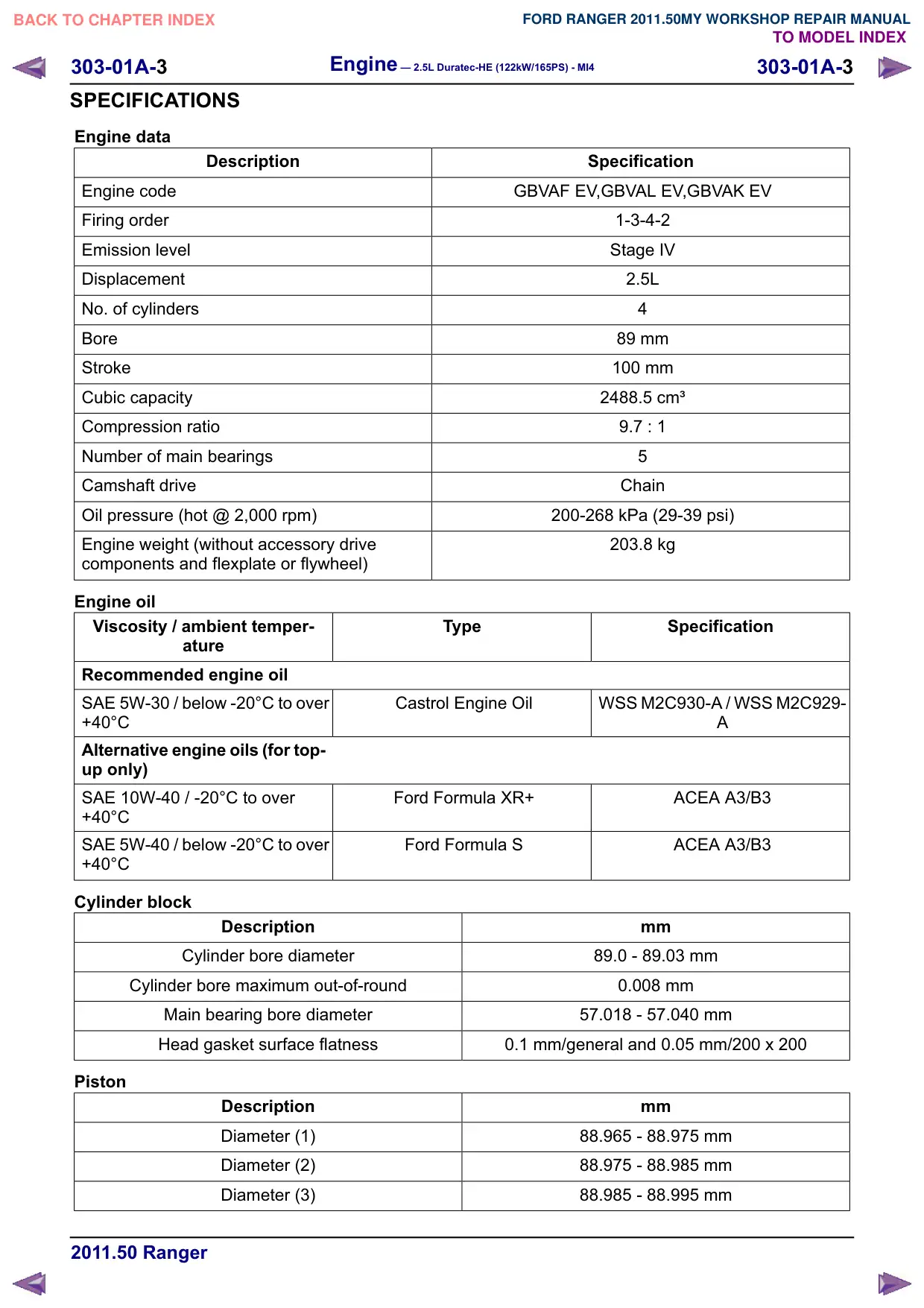
SPECIFICATIONS
Engine data
Description
Engine code
Firing order
Emission level
Displacement
No. of cylinders
Bore
Stroke
Cubic capacity
Compression ratio
Number of main bearings
Camshaft drive
Oil pressure (hot @ 2,000 rpm)
Engine weight (without accessory drive
components and flexplate or flywheel)
Engine oil
Viscosity / ambient temper-
DWXUH
Recommended engine oil
SAE 5W-30 / below -20°C to over
Castrol Engine Oil
+40°C
Alternative engine oils (for top-
up only)
SAE 10W-40 / -20°C to over
Ford Formula XR+
+40°C
SAE 5W-40 / below -20°C to over
Ford Formula S
+40°C
Cylinder block
Description
Cylinder bore diameter
Cylinder bore maximum out-of-round
Main bearing bore diameter
Head gasket surface flatness
Piston
Description
Diameter (1)
Diameter (2)
Diameter (3)
Specification
GBVAF EV,GBVAL EV,GBVAK EV
1-3-4-2
Stage IV
2.5L
4
89 mm
100 mm
2488.5 cm¹
9.7 : 1
5
Chain
200-268 kPa (29-39 psi)
203.8 kg
Type
Specification
WSS M2C930-A / WSS M2C929-
$
ACEA A3/B3
ACEA A3/B3
mm
89.0 - 89.03 mm
0.008 mm
57.018 - 57.040 mm
0.1 mm/general and 0.05 mm/200 x 200
mm
88.965 - 88.975 mm
88.975 - 88.985 mm
88.985 - 88.995 mm
Engine – 2.5L Duratec-HE (122kW/165PS) - MI4
303-01A-4
303-01A-4
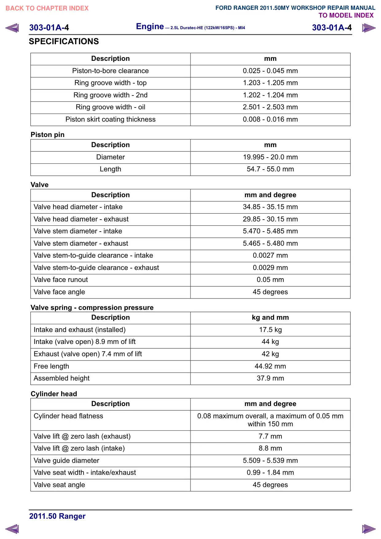
SPECIFICATIONS
Description
Piston-to-bore clearance
Ring groove width - top
Ring groove width - 2nd
Ring groove width - oil
Piston skirt coating thickness
Piston pin
Description
Diameter
Length
Valve
Description
Valve head diameter - intake
Valve head diameter - exhaust
Valve stem diameter - intake
Valve stem diameter - exhaust
Valve stem-to-guide clearance - intake
Valve stem-to-guide clearance - exhaust
Valve face runout
Valve face angle
Valve spring - compression pressure
Description
Intake and exhaust (installed)
Intake (valve open) 8.9 mm of lift
Exhaust (valve open) 7.4 mm of lift
Free length
Assembled height
Cylinder head
Description
Cylinder head flatness
Valve lift @ zero lash (exhaust)
Valve lift @ zero lash (intake)
Valve guide diameter
Valve seat width - intake/exhaust
Valve seat angle
mm
0.025 - 0.045 mm
1.203 - 1.205 mm
1.202 - 1.204 mm
2.501 - 2.503 mm
0.008 - 0.016 mm
mm
19.995 - 20.0 mm
54.7 - 55.0 mm
mm and degree
34.85 - 35.15 mm
29.85 - 30.15 mm
5.470 - 5.485 mm
5.465 - 5.480 mm
0.0027 mm
0.0029 mm
0.05 mm
45 degrees
kg and mm
17.5 kg
44 kg
42 kg
44.92 mm
37.9 mm
mm and degree
0.08 maximum overall, a maximum of 0.05 mm
within 150 mm
7.7 mm
8.8 mm
5.509 - 5.539 mm
0.99 - 1.84 mm
45 degrees
Engine – 2.5L Duratec-HE (122kW/165PS) - MI4
303-01A-5
303-01A-5
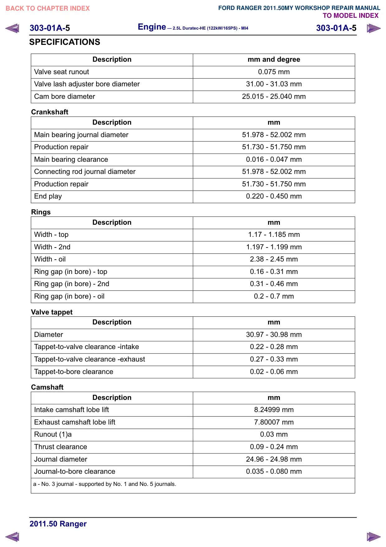
SPECIFICATIONS
Description
Valve seat runout
Valve lash adjuster bore diameter
Cam bore diameter
Crankshaft
Description
Main bearing journal diameter
Production repair
Main bearing clearance
Connecting rod journal diameter
Production repair
End play
Rings
Description
Width - top
Width - 2nd
Width - oil
Ring gap (in bore) - top
Ring gap (in bore) - 2nd
Ring gap (in bore) - oil
Valve tappet
Description
Diameter
Tappet-to-valve clearance -intake
Tappet-to-valve clearance -exhaust
Tappet-to-bore clearance
Camshaft
Description
Intake camshaft lobe lift
Exhaust camshaft lobe lift
Runout (1)a
Thrust clearance
Journal diameter
Journal-to-bore clearance
a - No. 3 journal - supported by No. 1 and No. 5 journals.
mm and degree
0.075 mm
31.00 - 31.03 mm
25.015 - 25.040 mm
mm
51.978 - 52.002 mm
51.730 - 51.750 mm
0.016 - 0.047 mm
51.978 - 52.002 mm
51.730 - 51.750 mm
0.220 - 0.450 mm
mm
1.17 - 1.185 mm
1.197 - 1.199 mm
2.38 - 2.45 mm
0.16 - 0.31 mm
0.31 - 0.46 mm
0.2 - 0.7 mm
mm
30.97 - 30.98 mm
0.22 - 0.28 mm
0.27 - 0.33 mm
0.02 - 0.06 mm
mm
8.24999 mm
7.80007 mm
0.03 mm
0.09 - 0.24 mm
24.96 - 24.98 mm
0.035 - 0.080 mm
303-01A-8
Engine – 2.5L Duratec-HE (122kW/165PS) - MI4
303-01A-8
DESCRIPTION AND OPERATION
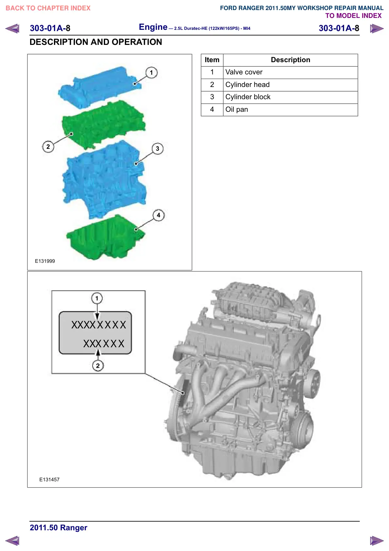
1
2
3
4
E131999
X
X
X
XXXXX
X
X
XXXX
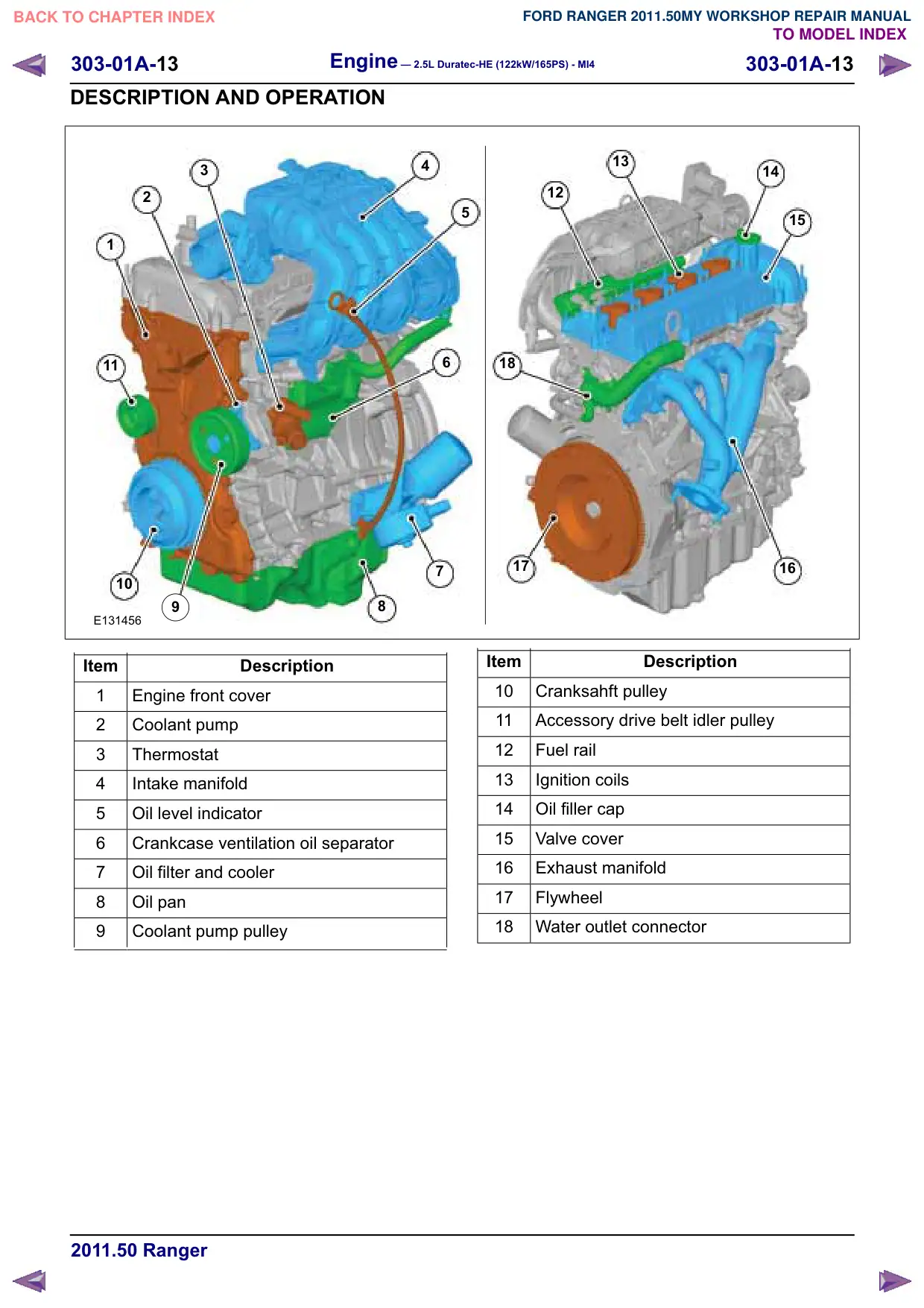
E131457
Item
Description
1
Valve cover
2
Cylinder head
3
Cylinder block
4
Oil pan
Engine – 2.5L Duratec-HE (122kW/165PS) - MI4
303-01A-
303-01A-
DESCRIPTION AND OPERATION
Item
Description
1
Engine code
Variable camshaft timing (VCT)
774
63
32
331
E83423
Item
Description
1
Control unit - variable camshaft timing
2
Camshaft bearing cap
3
VCT oil control solenoid
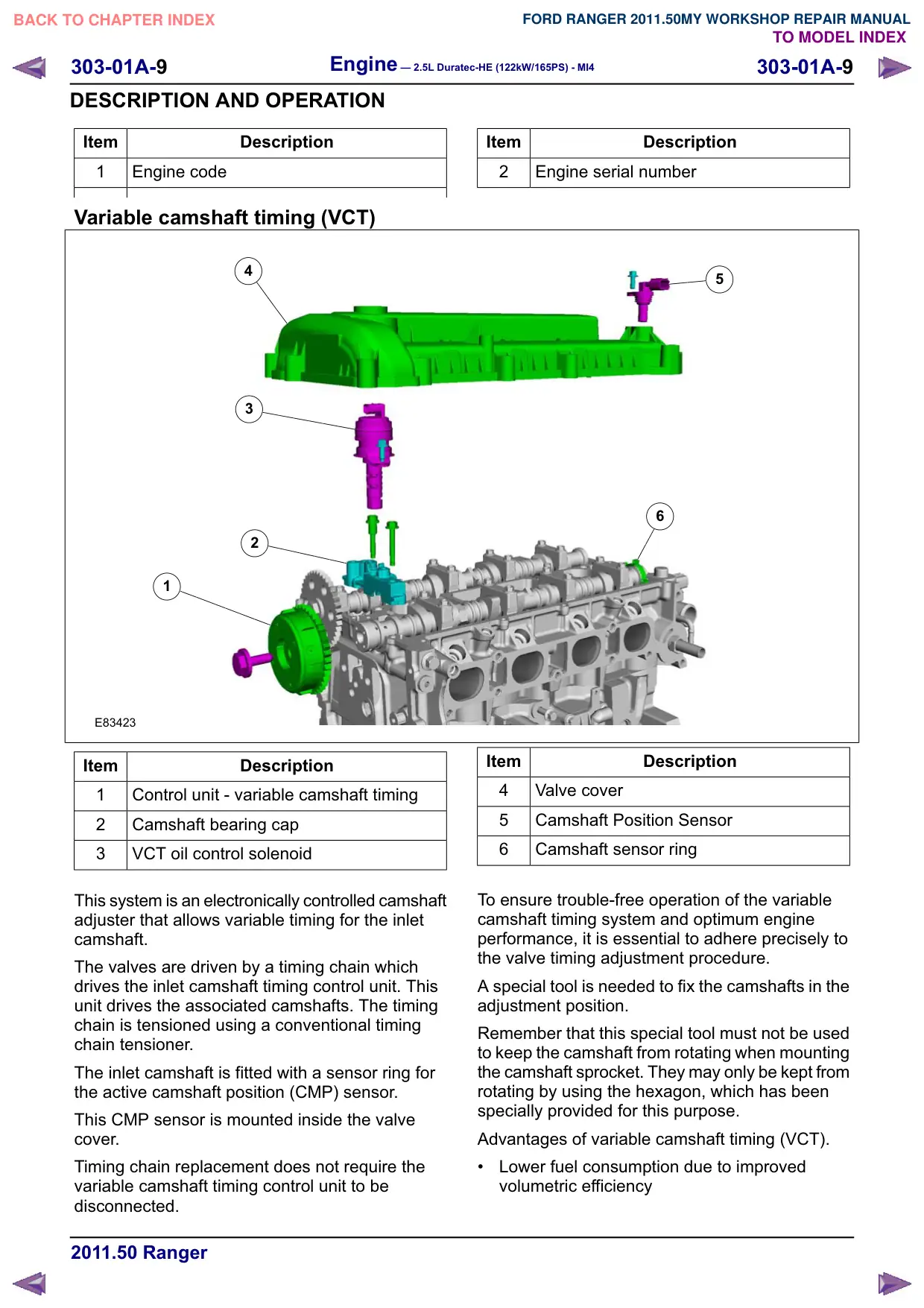
This system is an electronically controlled camshaft
adjuster that allows variable timing for the inlet
camshaft.
The valves are driven by a timing chain which
drives the inlet camshaft timing control unit. This
unit drives the associated camshafts. The timing
chain is tensioned using a conventional timing
chain tensioner.
The inlet camshaft is fitted with a sensor ring for
the active camshaft position (CMP) sensor.
This CMP sensor is mounted inside the valve
cover.
Timing chain replacement does not require the
variable camshaft timing control unit to be
disconnected.
Item
Description
2
Engine serial number
5
6
Item
Description
4
Valve cover
5
Camshaft Position Sensor
6
Camshaft sensor ring
To ensure trouble-free operation of the variable
camshaft timing system and optimum engine
performance, it is essential to adhere precisely to
the valve timing adjustment procedure.
A special tool is needed to fix the camshafts in the
adjustment position.
Remember that this special tool must not be used
to keep the camshaft from rotating when mounting
the camshaft sprocket. They may only be kept from
rotating by using the hexagon, which has been
specially provided for this purpose.
Advantages of variable camshaft timing (VCT).
Lower fuel consumption due to improved
volumetric efficiency
Engine – 2.5L Duratec-HE (122kW/165PS) - MI4
303-01A-11
303-01A-11
DESCRIPTION AND OPERATION
Item
Description
$
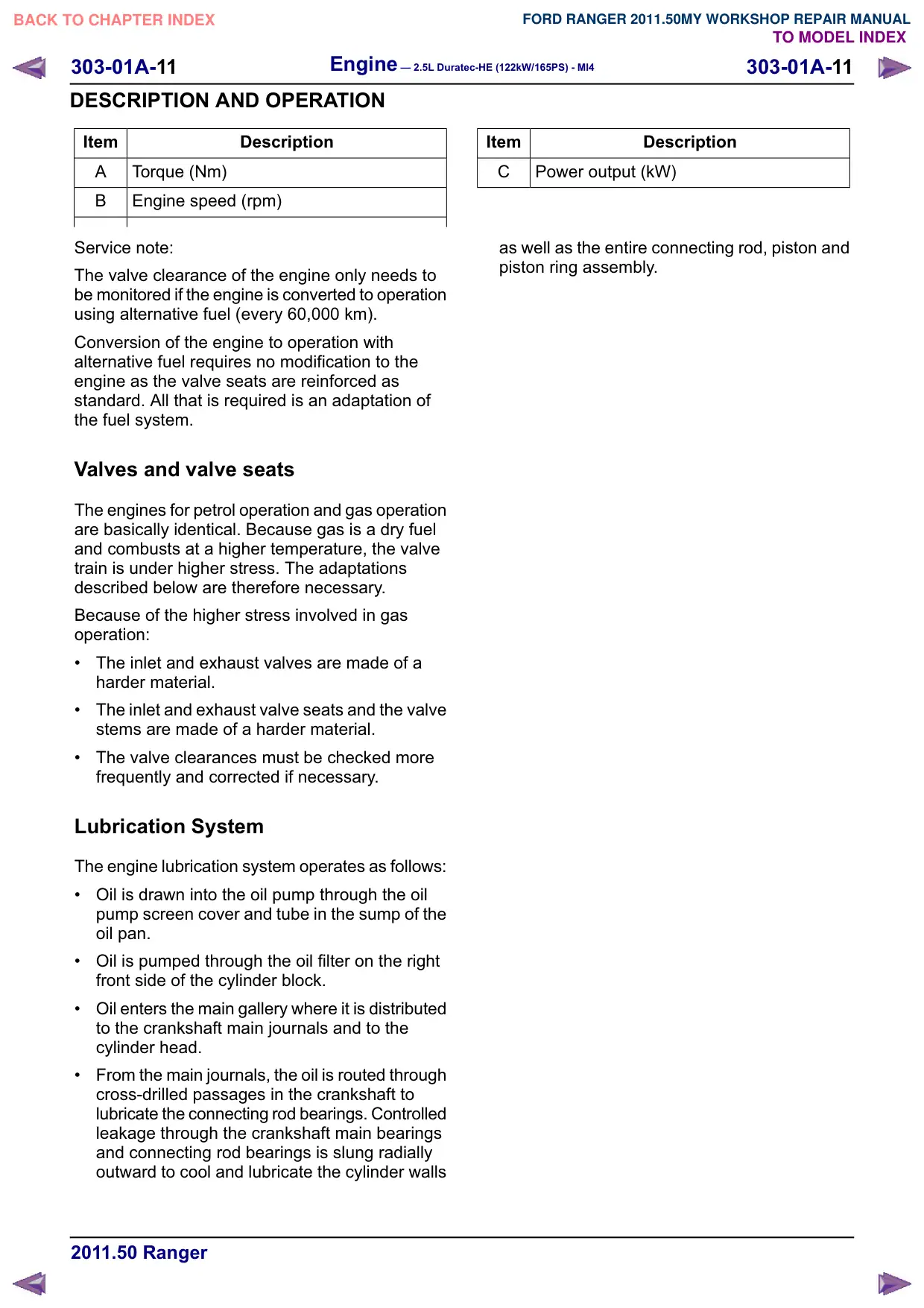
Torque (Nm)
%
Engine speed (rpm)
Service note:
The valve clearance of the engine only needs to
be monitored if the engine is converted to operation
using alternative fuel (every 60,000 km).
Conversion of the engine to operation with
alternative fuel requires no modification to the
engine as the valve seats are reinforced as
standard. All that is required is an adaptation of
the fuel system.
Valves and valve seats
The engines for petrol operation and gas operation
are basically identical. Because gas is a dry fuel
and combusts at a higher temperature, the valve
train is under higher stress. The adaptations
described below are therefore necessary.
Because of the higher stress involved in gas
operation:
The inlet and exhaust valves are made of a
harder material.
The inlet and exhaust valve seats and the valve
stems are made of a harder material.
The valve clearances must be checked more
frequently and corrected if necessary.
Lubrication System
The engine lubrication system operates as follows:
Oil is drawn into the oil pump through the oil
pump screen cover and tube in the sump of the
oil pan.
Oil is pumped through the oil filter on the right
front side of the cylinder block.
Oil enters the main gallery where it is distributed
to the crankshaft main journals and to the
cylinder head.
From the main journals, the oil is routed through
cross-drilled passages in the crankshaft to
lubricate the connecting rod bearings. Controlled
leakage through the crankshaft main bearings
and connecting rod bearings is slung radially
outward to cool and lubricate the cylinder walls
Item
Description
&
Power output (kW)
as well as the entire connecting rod, piston and
piston ring assembly.
303-01A-14
Engine – 2.5L Duratec-HE (122kW/165PS) - MI4
303-01A-14
DESCRIPTION AND OPERATION
X
X
X
XXXX
X
X
XXXX
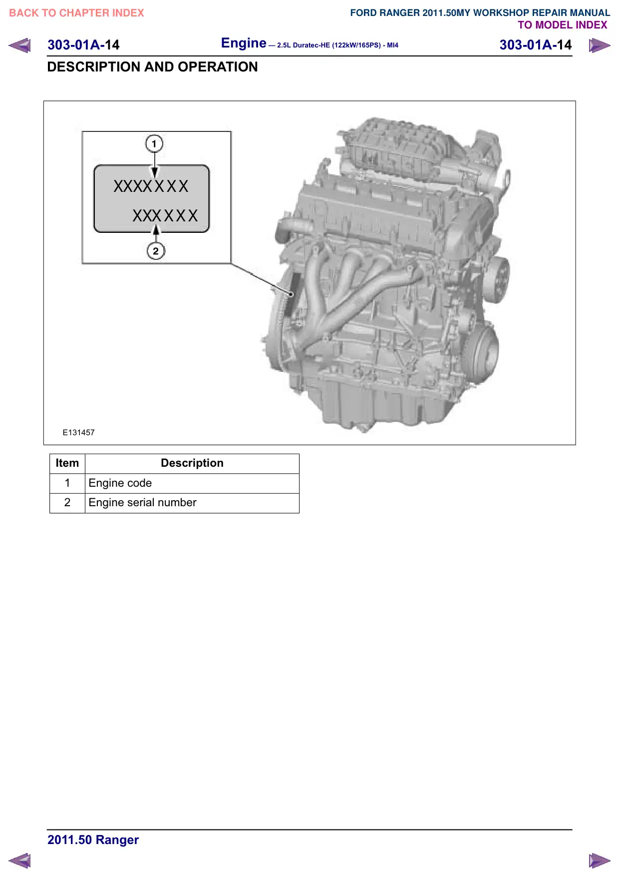
E131457
Item
Description
1
Engine code
2
Engine serial number
Engine – 2.5L Duratec-HE (122kW/165PS) - MI4
303-01A-15
303-01A-15
GENERAL PROCEDURES
Valve Clearance Adjustment
Special Tool(s) / General Equipment
303-465
Tool, Camshaft Align Timing
E134673
303-507
Timing Peg, Crankshaft TDC
PZ21210
2 mm Punch
Materials
Name
Specification
Hypoid Oil 85W-90
SQ-M2C9002-AA /
A72SX-19K261-CA
Thread Locking MS
WSK-M2G349-A7 /
2U7J-M2G349-AA
1. Refer to: Accessory Drive Belt (303-05
Accessory Drive - 2.5L Duratec-HE
(122kW/165PS) - MI4, Removal and
Installation).
2. Refer to: Valve Cover (303-01 Engine - 2.5L
Duratec-HE (122kW/165PS) - MI4, Removal
and Installation).
3.
CAUTION: Only rotate the crankshaft
clockwise.
NOTE: Before removing the camshafts,
measure the clearance of each valve at base
circle, with the lobe pointed away from the
tappet. Failure to measure all clearances prior
to removing the camshafts will necessitate
repeated removal and installation and wasted
labor time.
NOTE: If the valve clearance is less than
0.2mm, adjust the valves to the maximum
clearance.
Rotate the crankshaft until the cam pair of the
cylinder to be adjusted are pointing upwards.
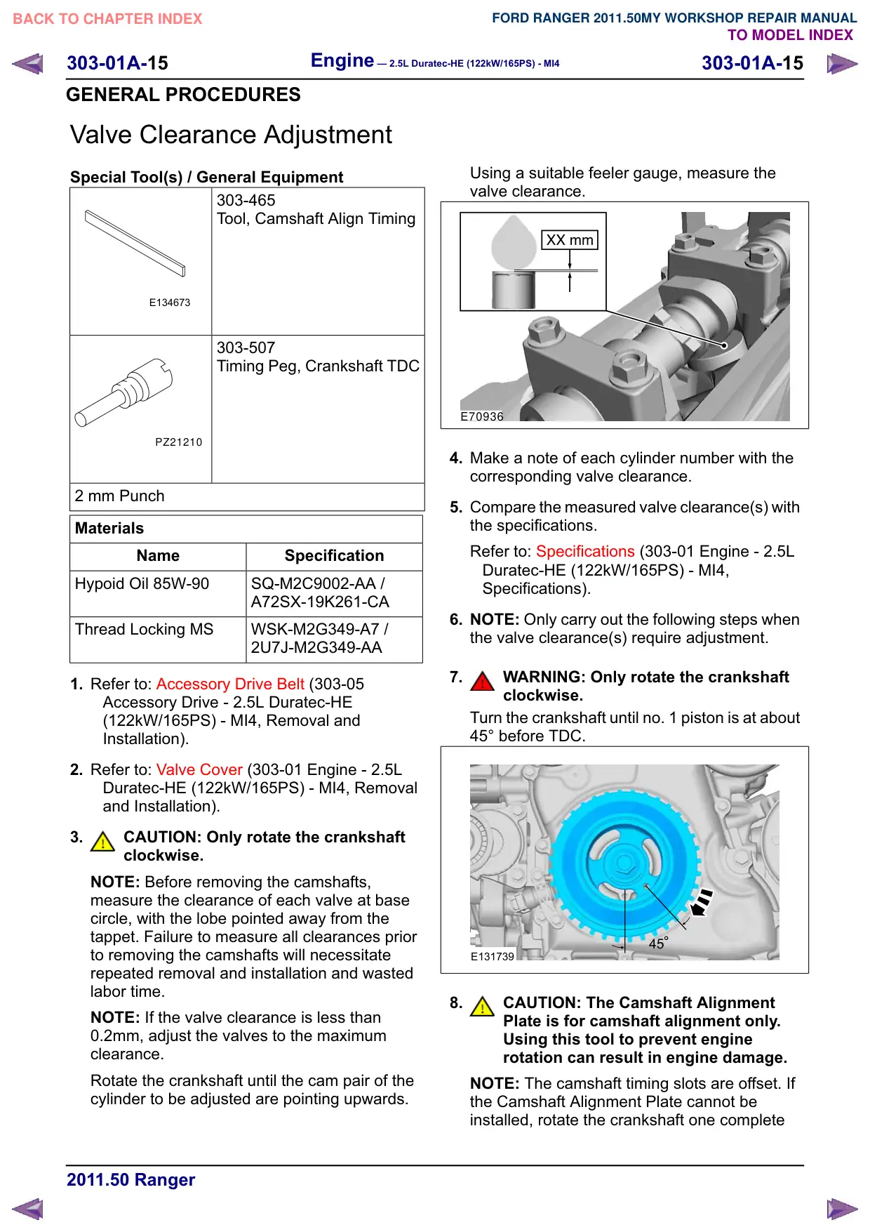
Using a suitable feeler gauge, measure the
valve clearance.
E70936
4. Make a note of each cylinder number with the
corresponding valve clearance.
5. Compare the measured valve clearance(s) with
the specifications.
Refer to: Specifications (303-01 Engine - 2.5L
Duratec-HE (122kW/165PS) - MI4,
Specifications).
6. NOTE: Only carry out the following steps when
the valve clearance(s) require adjustment.
7.
WARNING: Only rotate the crankshaft
clockwise.
Turn the crankshaft until no. 1 piston is at about
45° before TDC.
E131739
8.
CAUTION: The Camshaft Alignment
Plate is for camshaft alignment only.
Using this tool to prevent engine
rotation can result in engine damage.
NOTE: The camshaft timing slots are offset. If
the Camshaft Alignment Plate cannot be
installed, rotate the crankshaft one complete
Engine – 2.5L Duratec-HE (122kW/165PS) - MI4
303-01A-16
303-01A-16
GENERAL PROCEDURES
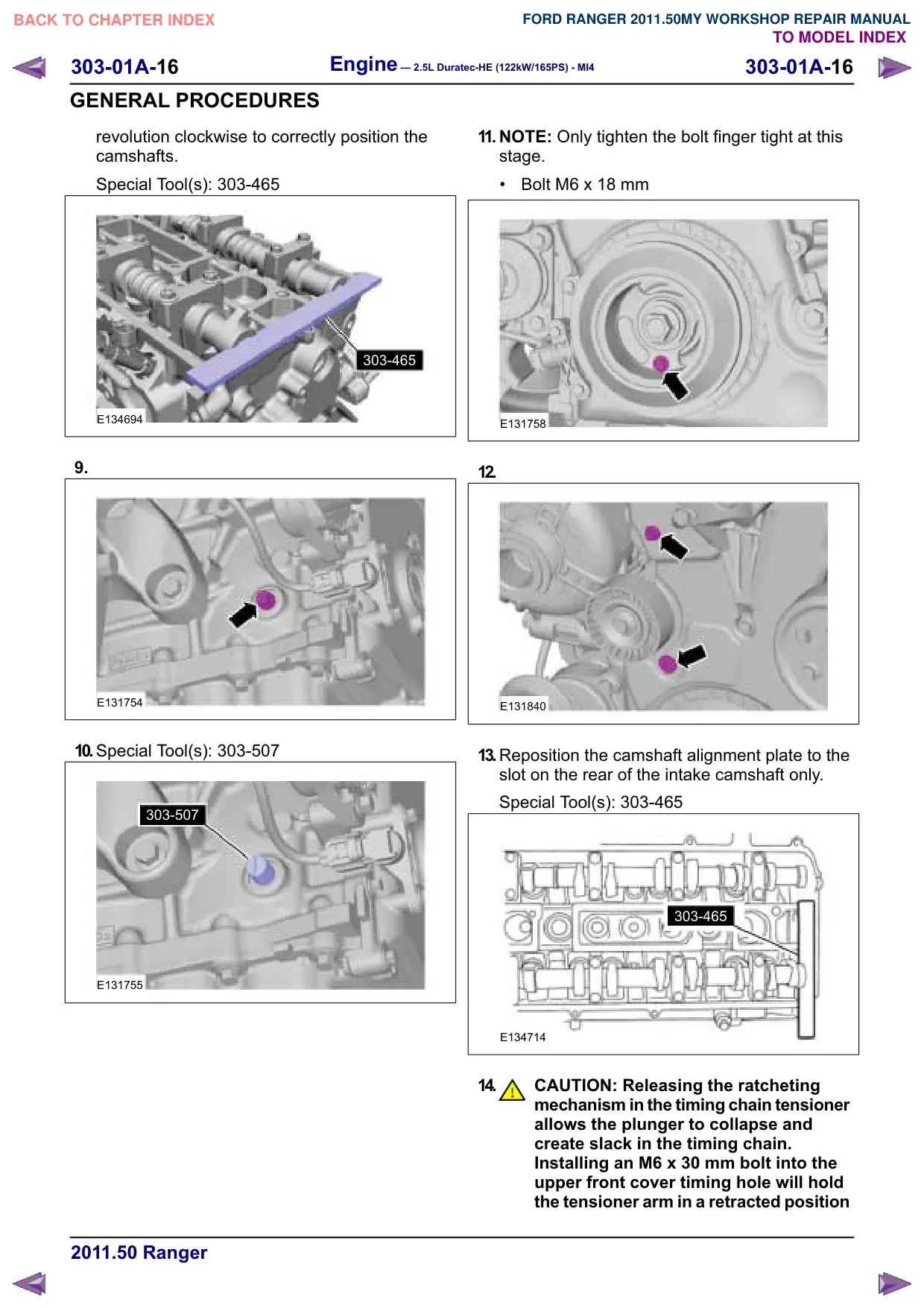
revolution clockwise to correctly position the
camshafts.
Special Tool(s): 303-465
303-465
E134694
9.
E131754
10.Special Tool(s): 303-507
303-507
E131755
11. NOTE: Only tighten the bolt finger tight at this
stage.
Bolt M6 x 18 mm
E131758
12.
E131840
13.Reposition the camshaft alignment plate to the
slot on the rear of the intake camshaft only.
Special Tool(s): 303-465
303-465
E134714
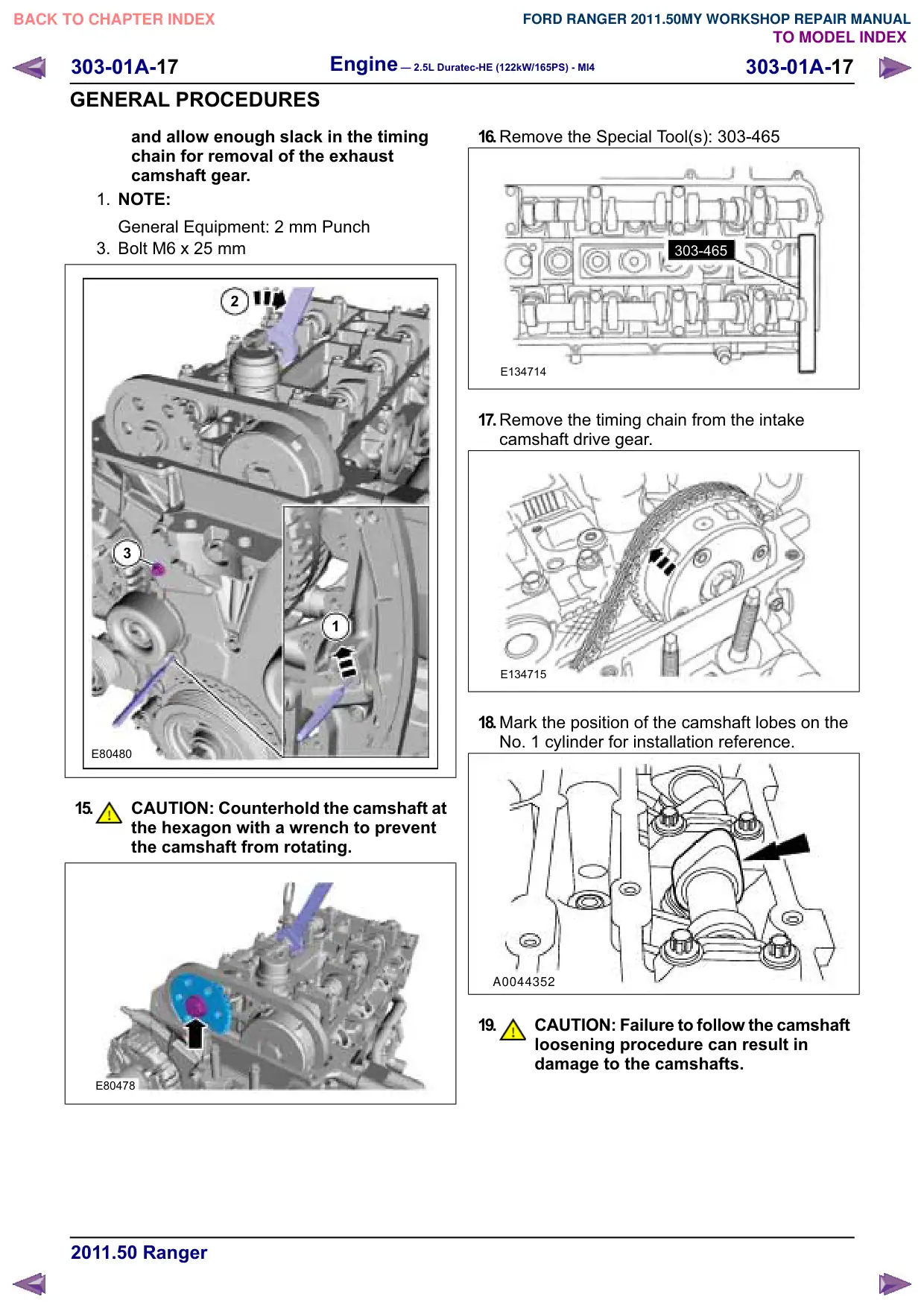
14.
CAUTION: Releasing the ratcheting
mechanism in the timing chain tensioner
allows the plunger to collapse and
create slack in the timing chain.
Installing an M6 x 30 mm bolt into the
upper front cover timing hole will hold
the tensioner arm in a retracted position
303-01A-17
Engine – 2.5L Duratec-HE (122kW/165PS) - MI4
303-01A-17
GENERAL PROCEDURES
and allow enough slack in the timing
chain for removal of the exhaust
camshaft gear.
1. NOTE:
General Equipment: 2 mm Punch
3. Bolt M6 x 25 mm
2
3
1
E80480
15.
CAUTION: Counterhold the camshaft at
the hexagon with a wrench to prevent
the camshaft from rotating.
E80478
16.Remove the Special Tool(s): 303-465
303-465
E134714
17.Remove the timing chain from the intake
camshaft drive gear.
E134715
18.Mark the position of the camshaft lobes on the
No. 1 cylinder for installation reference.
A0044352
19.
CAUTION: Failure to follow the camshaft
loosening procedure can result in
damage to the camshafts.
303-01A-18
Engine – 2.5L Duratec-HE (122kW/165PS) - MI4
303-01A-18
GENERAL PROCEDURES
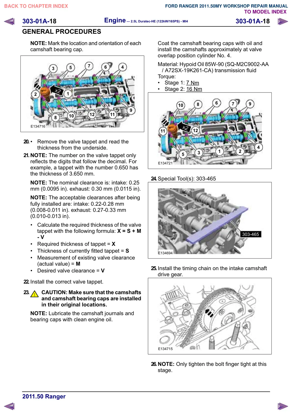
NOTE: Mark the location and orientation of each
camshaft bearing cap.
7
6
4
3
5
1
2
12
11
10
8
E134716
20.
Remove the valve tappet and read the
thickness from the underside.
21.NOTE: The number on the valve tappet only
reflects the digits that follow the decimal. For
example, a tappet with the number 0.650 has
the thickness of 3.650 mm.
NOTE: The nominal clearance is: intake: 0.25
mm (0.0095 in). exhaust: 0.30 mm (0.0115 in).
NOTE: The acceptable clearances after being
fully installed are: intake: 0.22-0.28 mm
(0.008-0.011 in). exhaust: 0.27-0.33 mm
(0.010-0.013 in).
Calculate the required thickness of the valve
tappet with the following formula: X S + M
- V
Required thickness of tappet ;
Thickness of currently fitted tappet 6
Measurement of existing valve clearance
(actual value) 0
Desired valve clearance 9
22.Install the correct valve tappet.
23.
CAUTION: Make sure that the camshafts
and camshaft bearing caps are installed
in their original locations.
NOTE: Lubricate the camshaft journals and
bearing caps with clean engine oil.
Coat the camshaft bearing caps with oil and
install the camshafts approximately at valve
overlap position cylinder No. 4.
Material: Hypoid Oil 85W-90 (SQ-M2C9002-AA
/ A72SX-19K261-CA) transmission fluid
Torque:
Stage 1: 7
Nm
Stage 2: 16 Nm
6
8
7
10
12
11
4
1
2
3
5
E134721
24.Special Tool(s): 303-465
303-465
E134694
25.Install the timing chain on the intake camshaft
drive gear.
E134715
26.NOTE: Only tighten the bolt finger tight at this
stage.
303-01A-19
Engine – 2.5L Duratec-HE (122kW/165PS) - MI4
303-01A-19
GENERAL PROCEDURES
NOTE: Make sure that the camshaft sprockets
can rotate on the camshafts.
NOTE: The timing chain must be correctly
engaged on the teeth of the crankshaft timing
sprocket and the intake camshaft drive gear in
order to install the exhaust camshaft drive gear
onto the exhaust camshaft.
E80478
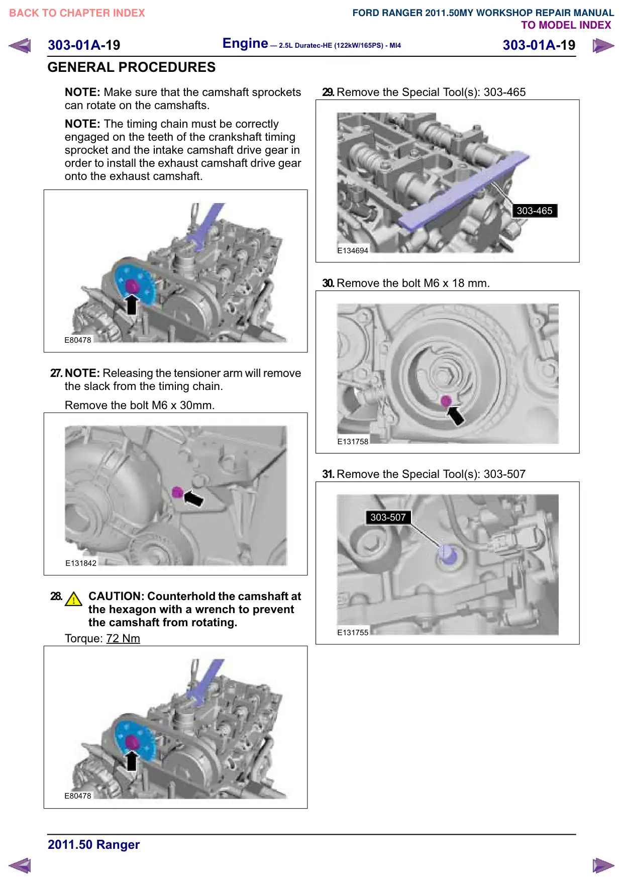
27.NOTE: Releasing the tensioner arm will remove
the slack from the timing chain.
Remove the bolt M6 x 30mm.
E131842
28.
CAUTION: Counterhold the camshaft at
the hexagon with a wrench to prevent
the camshaft from rotating.
Torque: 72 Nm
E80478
29.Remove the Special Tool(s): 303-465
303-465
E134694
30.Remove the bolt M6 x 18 mm.
E131758
31.Remove the Special Tool(s): 303-507
303-507
E131755
Engine – 2.5L Duratec-HE (122kW/165PS) - MI4
303-01A-21
303-01A-21
GENERAL PROCEDURES
Balance Shaft Backlash
Special Tool(s)
100-002
Holding Fixture with Dial
Indicator Gauge
E139373
303-507
Timing Peg, Crankshaft TDC
PZ21210
Adjustment
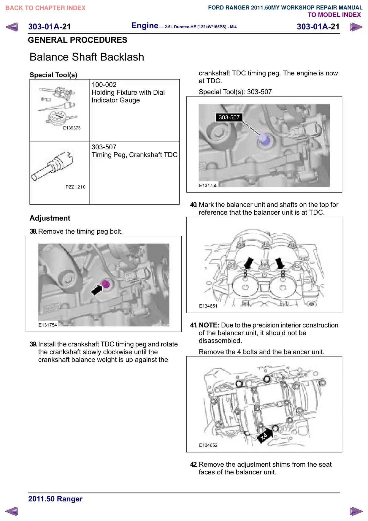
38.Remove the timing peg bolt.
E131754
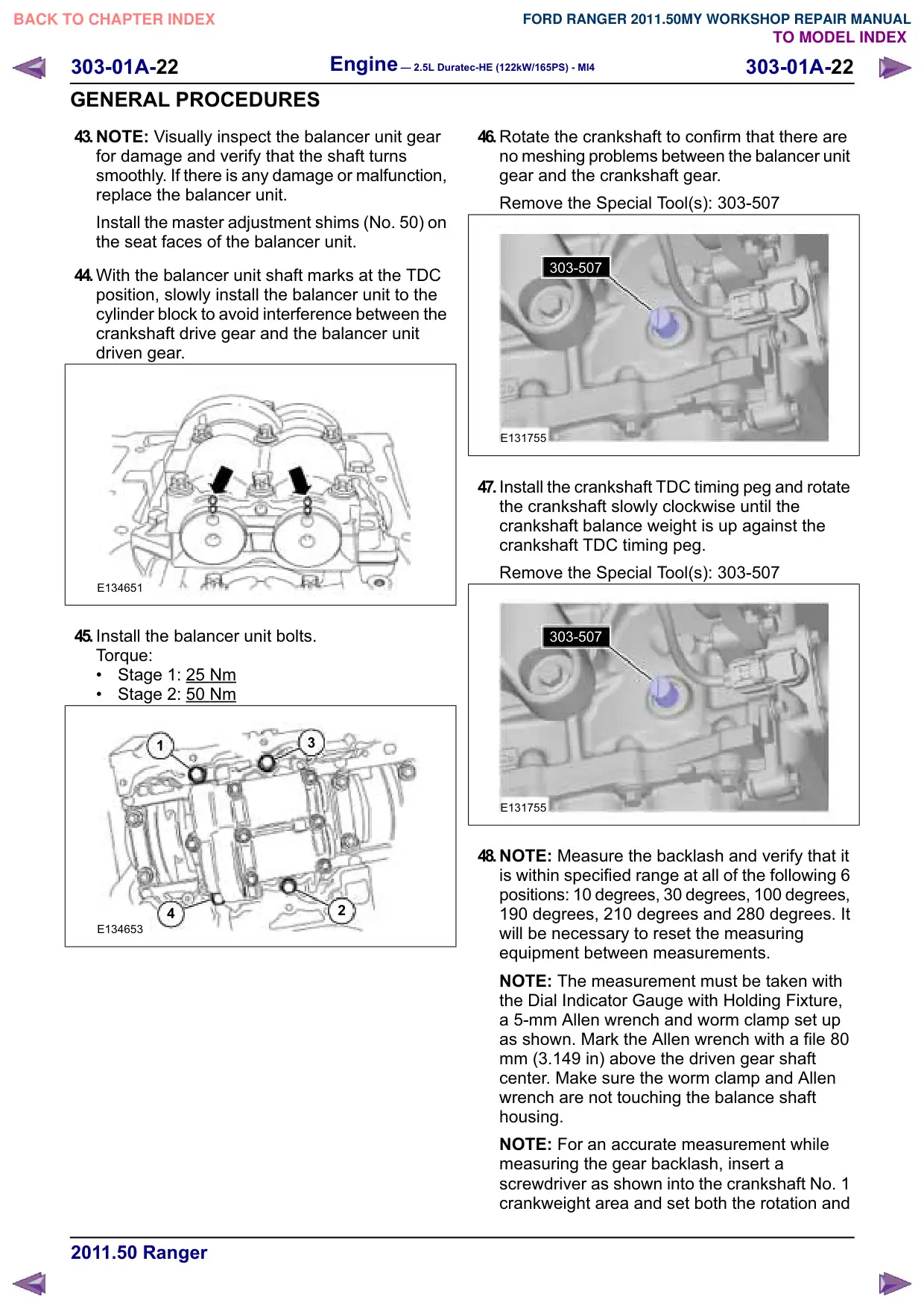
39.Install the crankshaft TDC timing peg and rotate
the crankshaft slowly clockwise until the
crankshaft balance weight is up against the
crankshaft TDC timing peg. The engine is now
at TDC.
Special Tool(s): 303-507
303-507
E131755
40.Mark the balancer unit and shafts on the top for
reference that the balancer unit is at TDC.
E134651
41.NOTE: Due to the precision interior construction
of the balancer unit, it should not be
disassembled.
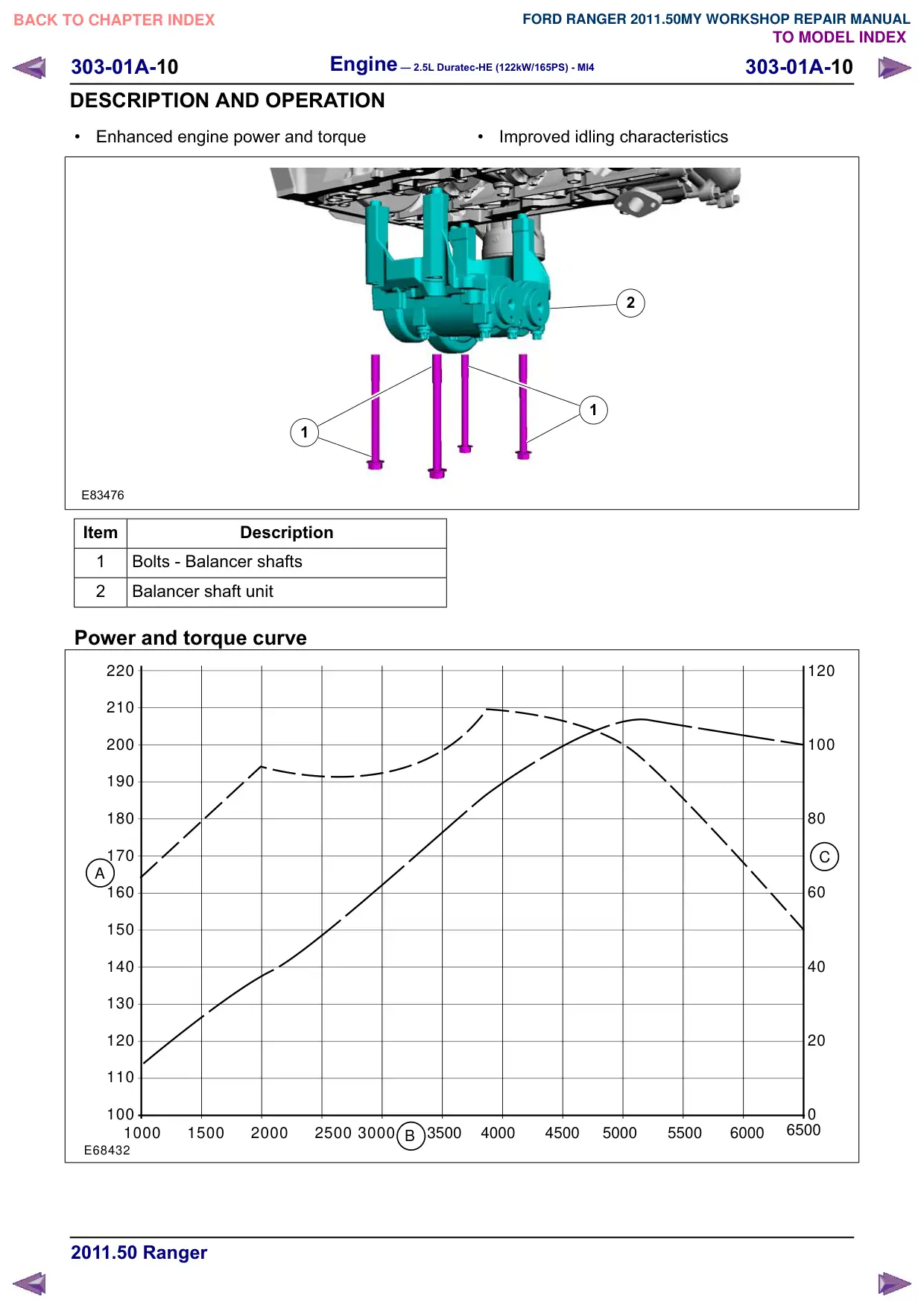
Remove the 4 bolts and the balancer unit.
x4
E134652
42.Remove the adjustment shims from the seat
faces of the balancer unit.
303-01A-22
Engine – 2.5L Duratec-HE (122kW/165PS) - MI4
303-01A-22
GENERAL PROCEDURES
43.NOTE: Visually inspect the balancer unit gear
for damage and verify that the shaft turns
smoothly. If there is any damage or malfunction,
replace the balancer unit.
Install the master adjustment shims (No. 50) on
the seat faces of the balancer unit.
44.With the balancer unit shaft marks at the TDC
position, slowly install the balancer unit to the
cylinder block to avoid interference between the
crankshaft drive gear and the balancer unit
driven gear.
E134651
45.Install the balancer unit bolts.
Torque:
Stage 1: 25
Nm
Stage 2: 50 Nm
3
1
2
4
E134653
46.Rotate the crankshaft to confirm that there are
no meshing problems between the balancer unit
gear and the crankshaft gear.
Remove the Special Tool(s): 303-507
303-507
E131755
47.Install the crankshaft TDC timing peg and rotate
the crankshaft slowly clockwise until the
crankshaft balance weight is up against the
crankshaft TDC timing peg.
Remove the Special Tool(s): 303-507
303-507
E131755
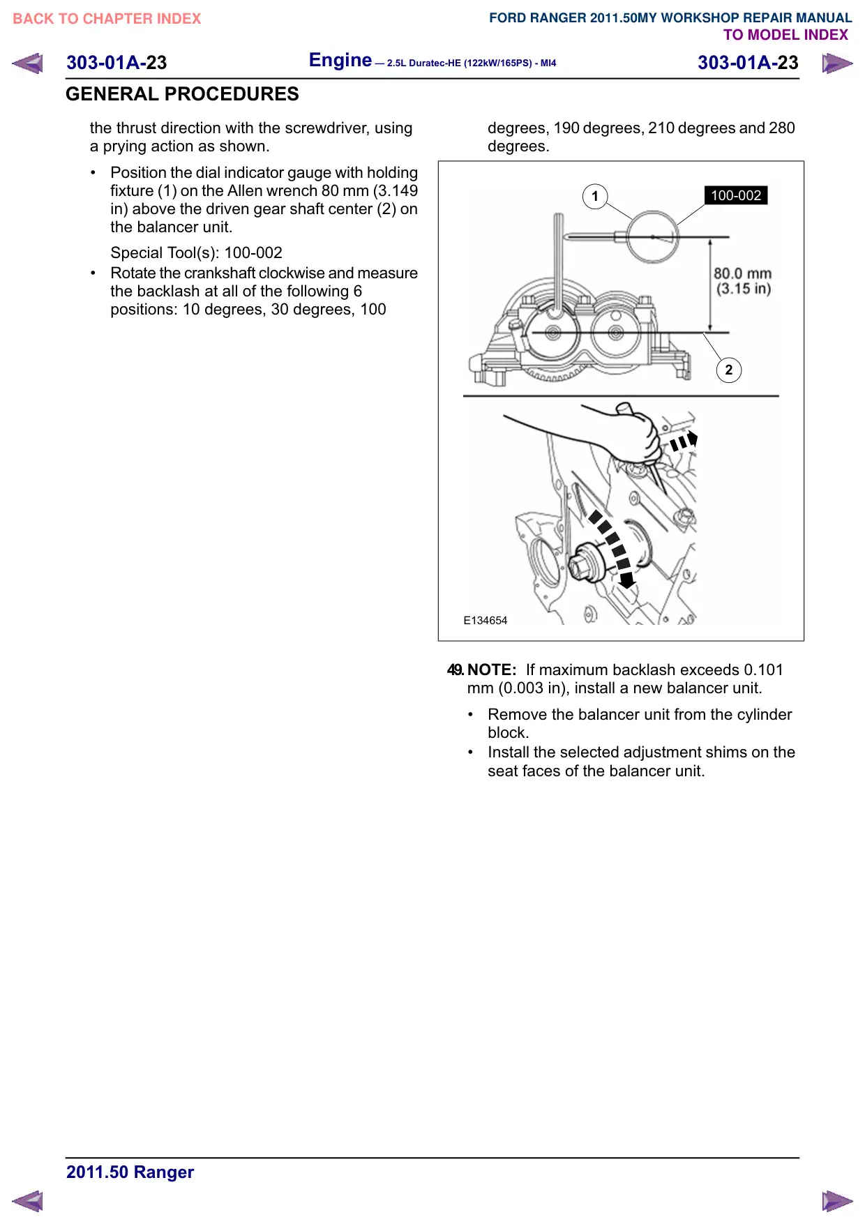
48.NOTE: Measure the backlash and verify that it
is within specified range at all of the following 6
positions: 10 degrees, 30 degrees, 100 degrees,
190 degrees, 210 degrees and 280 degrees. It
will be necessary to reset the measuring
equipment between measurements.
NOTE: The measurement must be taken with
the Dial Indicator Gauge with Holding Fixture,
a 5-mm Allen wrench and worm clamp set up
as shown. Mark the Allen wrench with a file 80
mm (3.149 in) above the driven gear shaft
center. Make sure the worm clamp and Allen
wrench are not touching the balance shaft
housing.
NOTE: For an accurate measurement while
measuring the gear backlash, insert a
screwdriver as shown into the crankshaft No. 1
crankweight area and set both the rotation and
Engine – 2.5L Duratec-HE (122kW/165PS) - MI4
303-01A-23
303-01A-23
GENERAL PROCEDURES
the thrust direction with the screwdriver, using
a prying action as shown.
Position the dial indicator gauge with holding
fixture (1) on the Allen wrench 80 mm (3.149
in) above the driven gear shaft center (2) on
the balancer unit.
Special Tool(s): 100-002
Rotate the crankshaft clockwise and measure
the backlash at all of the following 6
positions: 10 degrees, 30 degrees, 100
degrees, 190 degrees, 210 degrees and 280
degrees.
100-002
1
2
E134654
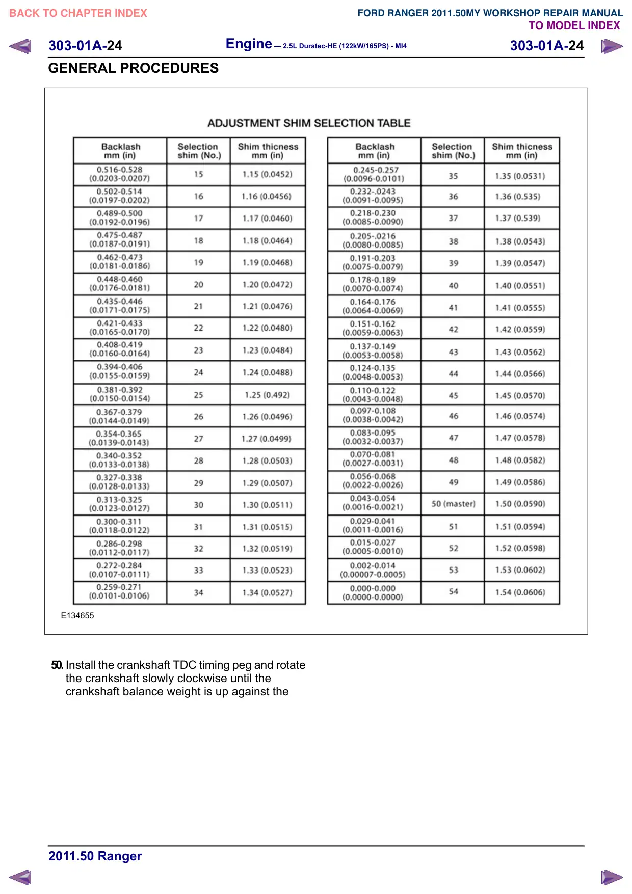
49.NOTE: If maximum backlash exceeds 0.101
mm (0.003 in), install a new balancer unit.
Remove the balancer unit from the cylinder
block.
Install the selected adjustment shims on the
seat faces of the balancer unit.
303-01A-24
Engine – 2.5L Duratec-HE (122kW/165PS) - MI4
303-01A-24
GENERAL PROCEDURES
E134655
50.Install the crankshaft TDC timing peg and rotate
the crankshaft slowly clockwise until the
crankshaft balance weight is up against the
Engine – 2.5L Duratec-HE (122kW/165PS) - MI4
303-01A-25
303-01A-25
GENERAL PROCEDURES
crankshaft TDC timing peg. The engine is now
at TDC.
Special Tool(s): 303-507
303-507
E131755
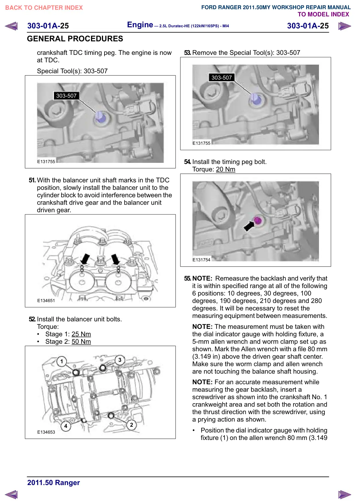
51.With the balancer unit shaft marks in the TDC
position, slowly install the balancer unit to the
cylinder block to avoid interference between the
crankshaft drive gear and the balancer unit
driven gear.
E134651
52.Install the balancer unit bolts.
Torque:
Stage 1: 25
Nm
Stage 2: 50 Nm
3
1
2
4
E134653
53.Remove the Special Tool(s): 303-507
303-507
E131755
54.Install the timing peg bolt.
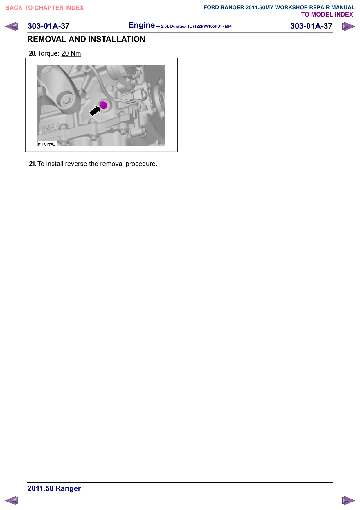
Torque: 20
Nm
E131754
55.NOTE: Remeasure the backlash and verify that
it is within specified range at all of the following
6 positions: 10 degrees, 30 degrees, 100
degrees, 190 degrees, 210 degrees and 280
degrees. It will be necessary to reset the
measuring equipment between measurements.
NOTE: The measurement must be taken with
the dial indicator gauge with holding fixture, a
5-mm allen wrench and worm clamp set up as
shown. Mark the Allen wrench with a file 80 mm
(3.149 in) above the driven gear shaft center.
Make sure the worm clamp and allen wrench
are not touching the balance shaft housing.
NOTE: For an accurate measurement while
measuring the gear backlash, insert a
screwdriver as shown into the crankshaft No. 1
crankweight area and set both the rotation and
the thrust direction with the screwdriver, using
a prying action as shown.
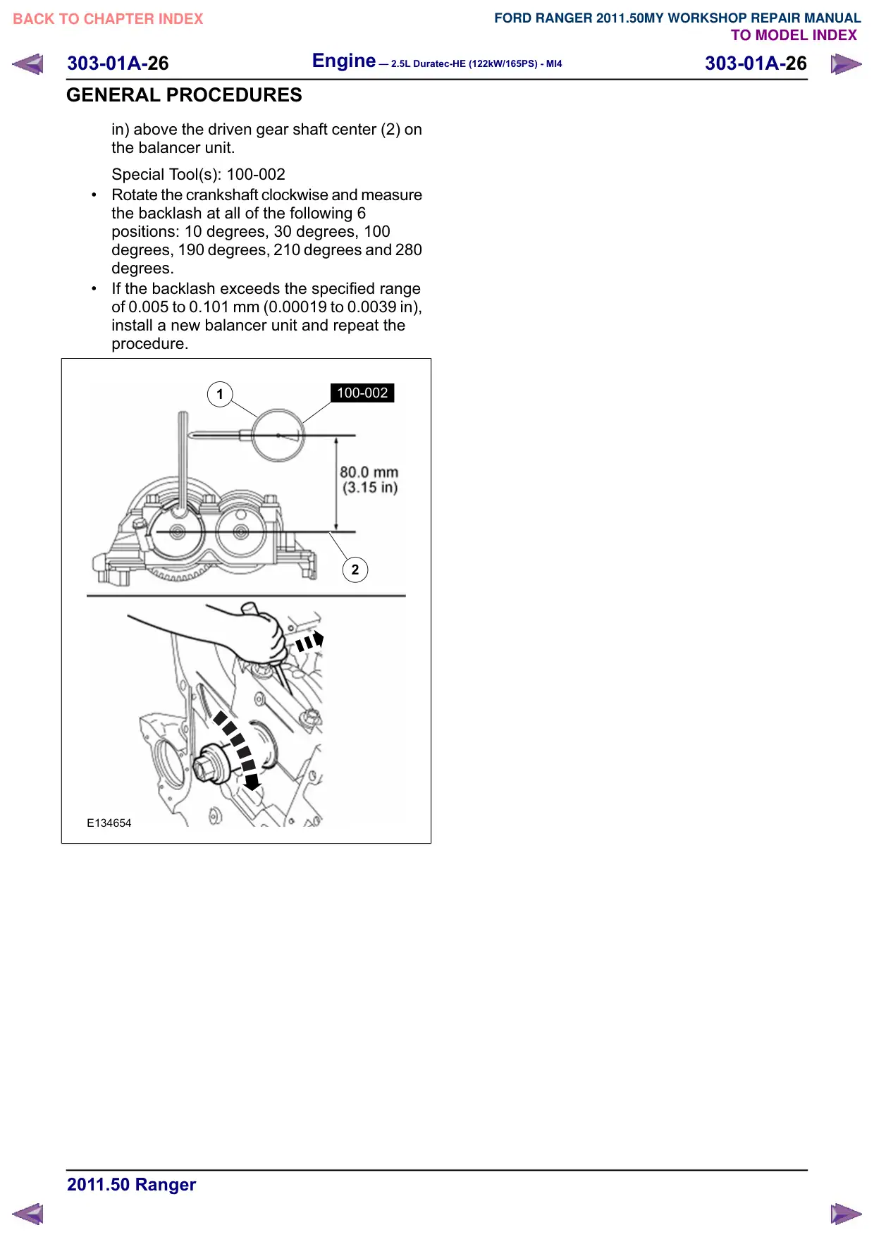
Position the dial indicator gauge with holding
fixture (1) on the allen wrench 80 mm (3.149
Engine – 2.5L Duratec-HE (122kW/165PS) - MI4
303-01A-26
303-01A-26
GENERAL PROCEDURES
in) above the driven gear shaft center (2) on
the balancer unit.
Special Tool(s): 100-002
Rotate the crankshaft clockwise and measure
the backlash at all of the following 6
positions: 10 degrees, 30 degrees, 100
degrees, 190 degrees, 210 degrees and 280
degrees.
If the backlash exceeds the specified range
of 0.005 to 0.101 mm (0.00019 to 0.0039 in),
install a new balancer unit and repeat the
procedure.
1
100-002
2
E134654
Engine – 2.5L Duratec-HE (122kW/165PS) - MI4
303-01A-27
303-01A-27
REMOVAL AND INSTALLATION
Camshafts(21 284 0)
Special Tool(s) / General Equipment
303-465
Tool, Camshaft Align Timing
E134673
303-507
Timing Peg, Crankshaft TDC
PZ21210
2 mm Punch
Materials
Name
Specification
Hypoid Oil 85W-90
SQ-M2C9002-AA /
A72SX-19K261-CA
Thread Locking MS
WSK-M2G349-A7 /
2U7J-M2G349-AA
Removal
NOTE: Removal steps in this procedure may
contain installation details.
1. Refer to: Accessory Drive Belt (303-05
Accessory Drive - 2.5L Duratec-HE
(122kW/165PS) - MI4, Removal and
Installation).
2. CAUTIONS:
During engine repair procedures,
cleanliness is extremely important. Any
foreign material (including any material
created while cleaning gasket surfaces)
that enters the oil passages, coolant
passages or the oil pan can cause
engine failure.
Do not rotate the camshafts unless
instructed to in this procedure. Rotating
the camshafts or crankshaft with timing
components loosened or removed can
cause serious damage to the valves and
pistons.
Refer to: Valve Cover (303-01 Engine - 2.5L
Duratec-HE (122kW/165PS) - MI4, Removal
and Installation).
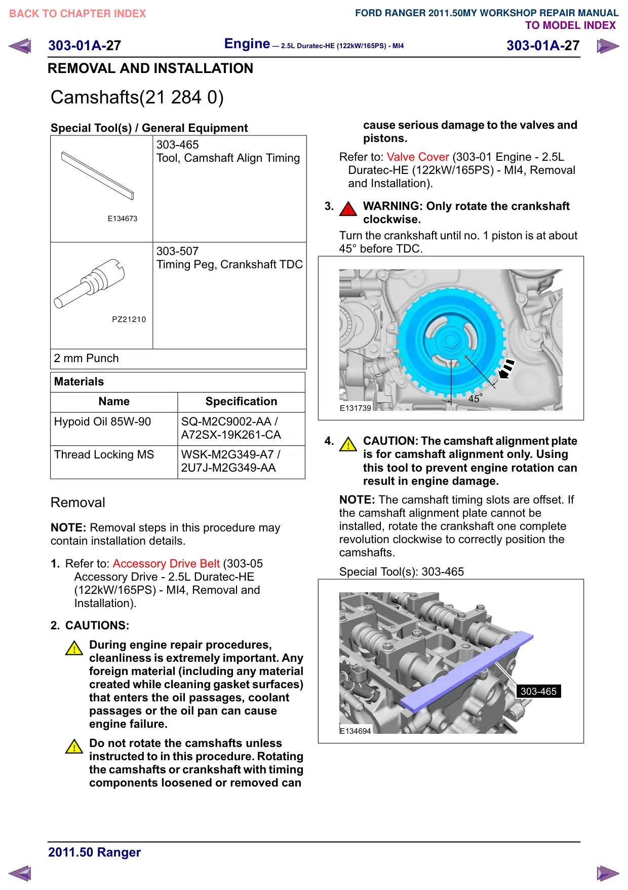
3.
WARNING: Only rotate the crankshaft
clockwise.
Turn the crankshaft until no. 1 piston is at about
45° before TDC.
E131739
4.
CAUTION: The camshaft alignment plate
is for camshaft alignment only. Using
this tool to prevent engine rotation can
result in engine damage.
NOTE: The camshaft timing slots are offset. If
the camshaft alignment plate cannot be
installed, rotate the crankshaft one complete
revolution clockwise to correctly position the
camshafts.
Special Tool(s): 303-465
303-465
E134694
303-01A-28
Engine – 2.5L Duratec-HE (122kW/165PS) - MI4
303-01A-28
REMOVAL AND INSTALLATION
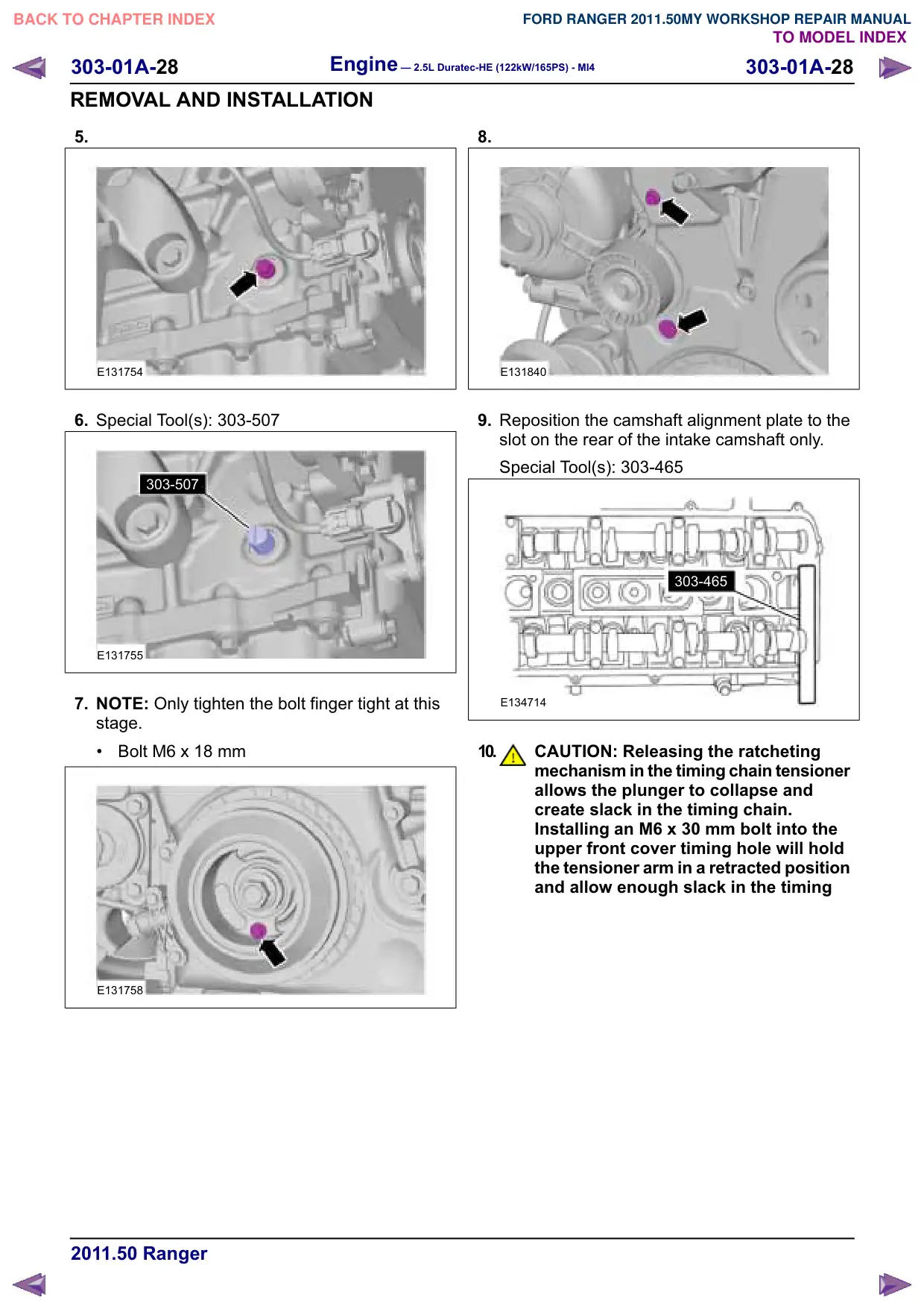
5.
E131754
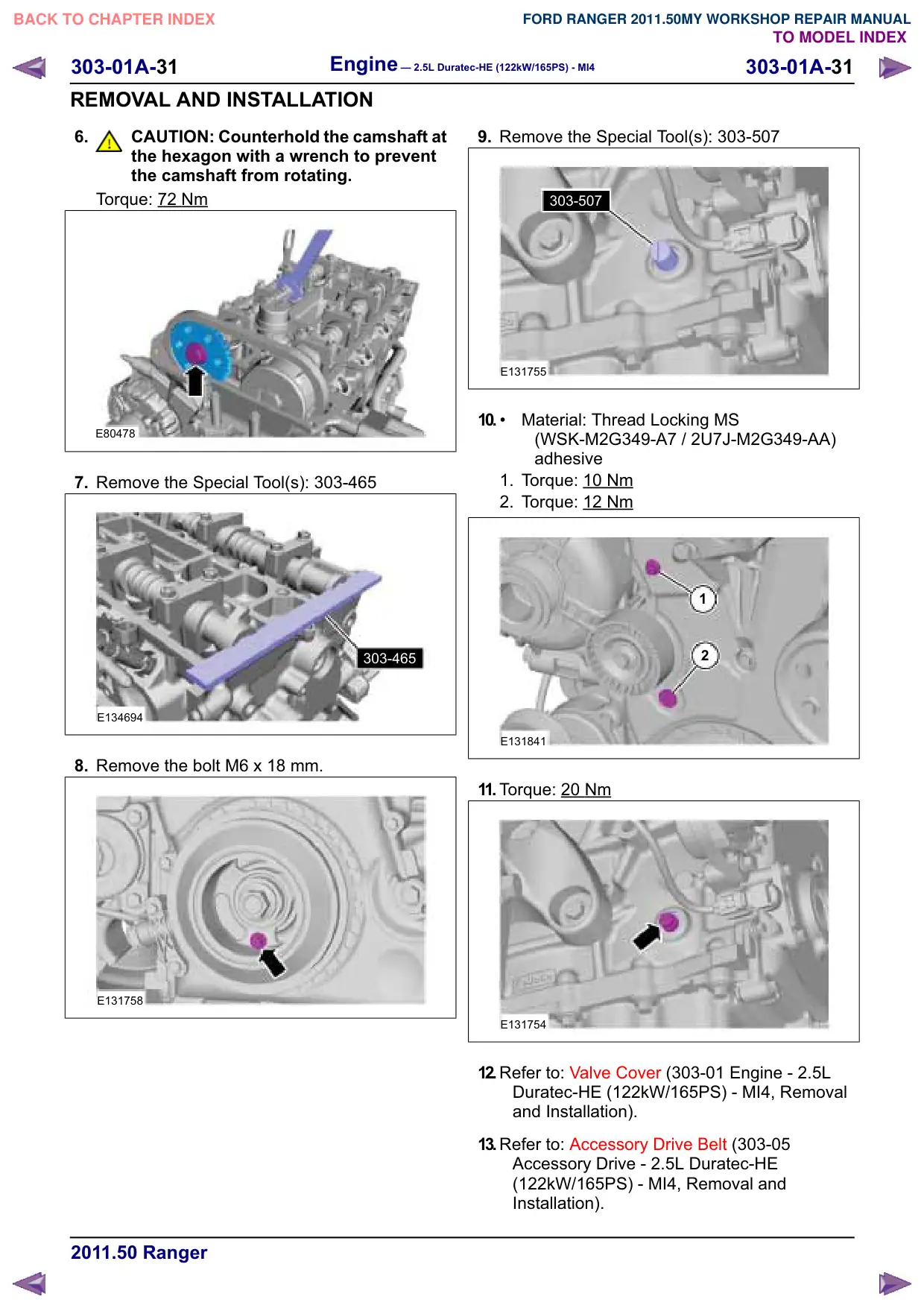
6. Special Tool(s): 303-507
303-507
E131755
7. NOTE: Only tighten the bolt finger tight at this
stage.
Bolt M6 x 18 mm
E131758
8.
E131840
9. Reposition the camshaft alignment plate to the
slot on the rear of the intake camshaft only.
Special Tool(s): 303-465
303-465
E134714
10.
CAUTION: Releasing the ratcheting
mechanism in the timing chain tensioner
allows the plunger to collapse and
create slack in the timing chain.
Installing an M6 x 30 mm bolt into the
upper front cover timing hole will hold
the tensioner arm in a retracted position
and allow enough slack in the timing
303-01A-29
Engine – 2.5L Duratec-HE (122kW/165PS) - MI4
303-01A-29
REMOVAL AND INSTALLATION
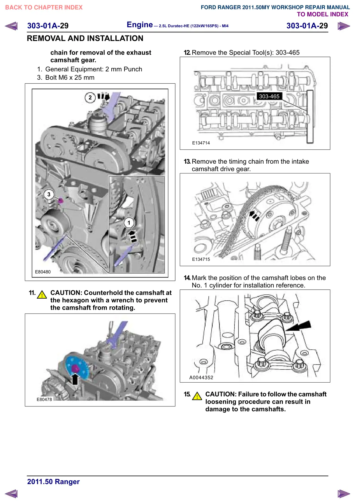
chain for removal of the exhaust
camshaft gear.
1. General Equipment: 2 mm Punch
3. Bolt M6 x 25 mm
2
3
1
E80480
11.
CAUTION: Counterhold the camshaft at
the hexagon with a wrench to prevent
the camshaft from rotating.
E80478
12.Remove the Special Tool(s): 303-465
303-465
E134714
13.Remove the timing chain from the intake
camshaft drive gear.
E134715
14.Mark the position of the camshaft lobes on the
No. 1 cylinder for installation reference.
A0044352
15.
CAUTION: Failure to follow the camshaft
loosening procedure can result in
damage to the camshafts.
Engine – 2.5L Duratec-HE (122kW/165PS) - MI4
303-01A-30
303-01A-30
REMOVAL AND INSTALLATION
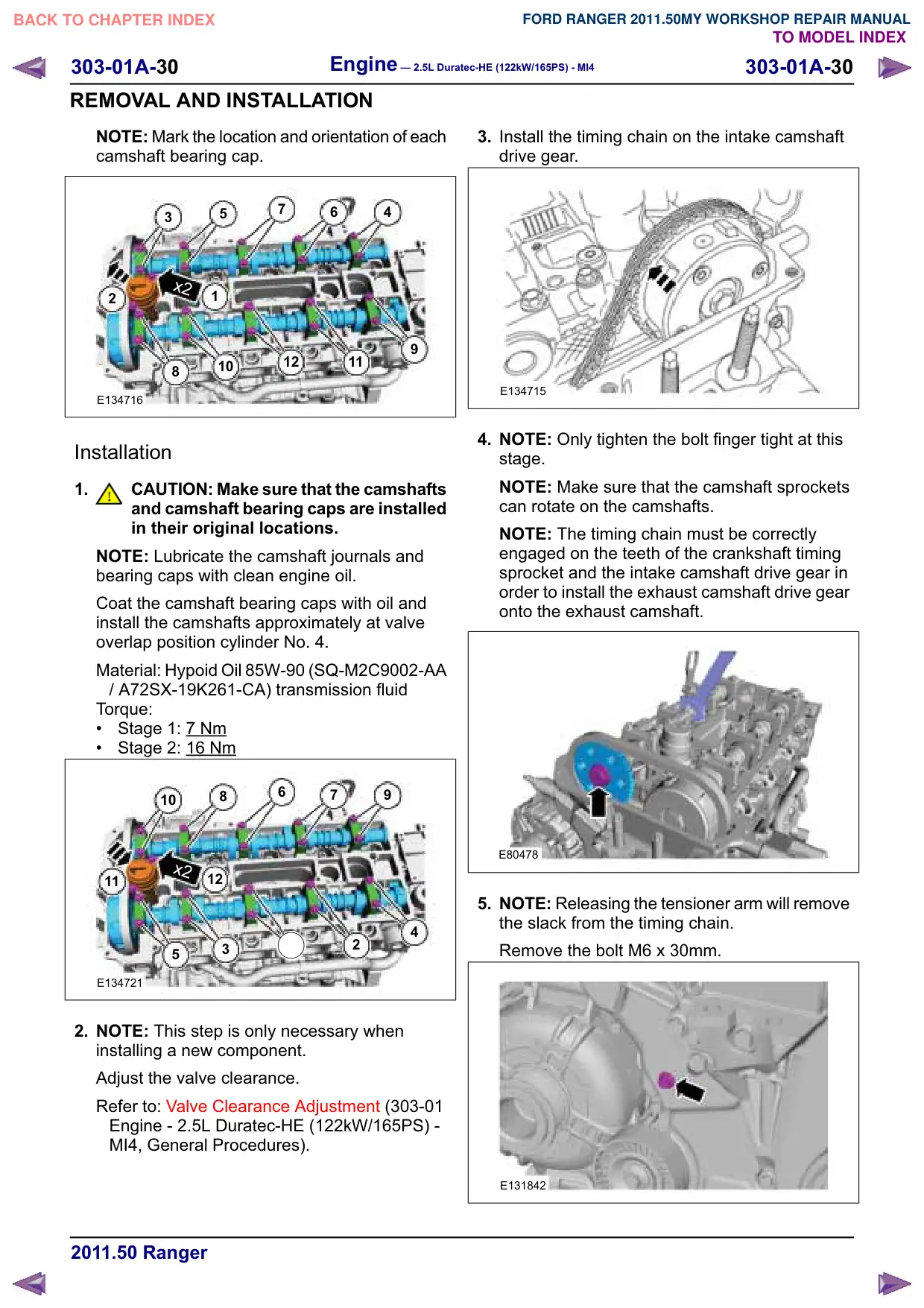
NOTE: Mark the location and orientation of each
camshaft bearing cap.
7
6
4
3
5
x2
1
2
12
11
10
8
E134716
Installation
1.
CAUTION: Make sure that the camshafts
and camshaft bearing caps are installed
in their original locations.
NOTE: Lubricate the camshaft journals and
bearing caps with clean engine oil.
Coat the camshaft bearing caps with oil and
install the camshafts approximately at valve
overlap position cylinder No. 4.
Material: Hypoid Oil 85W-90 (SQ-M2C9002-AA
/ A72SX-19K261-CA) transmission fluid
Torque:
Stage 1: 7
Nm
Stage 2: 16 Nm
6
7
10
8
x2
12
11
4
3
2
5
E134721
2. NOTE: This step is only necessary when
installing a new component.
Adjust the valve clearance.
Refer to: Valve Clearance Adjustment (303-01
Engine - 2.5L Duratec-HE (122kW/165PS) -
MI4, General Procedures).
3. Install the timing chain on the intake camshaft
drive gear.
E134715
4. NOTE: Only tighten the bolt finger tight at this
stage.
NOTE: Make sure that the camshaft sprockets
can rotate on the camshafts.
NOTE: The timing chain must be correctly
engaged on the teeth of the crankshaft timing
sprocket and the intake camshaft drive gear in
order to install the exhaust camshaft drive gear
onto the exhaust camshaft.
E80478
5. NOTE: Releasing the tensioner arm will remove
the slack from the timing chain.
Remove the bolt M6 x 30mm.
E131842
Engine – 2.5L Duratec-HE (122kW/165PS) - MI4
303-01A-32
303-01A-32
REMOVAL AND INSTALLATION
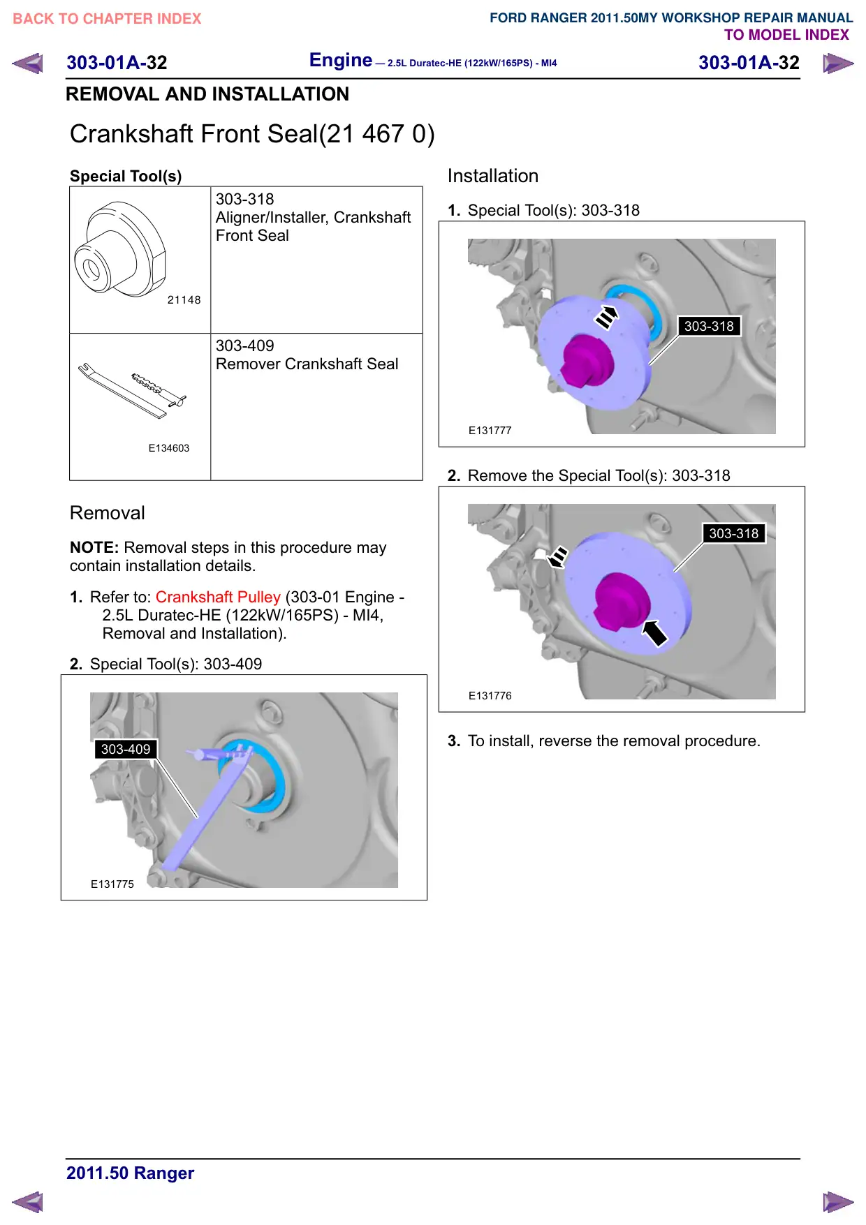
Crankshaft Front Seal(21 467 0)
Special Tool(s)
303-318
Aligner/Installer, Crankshaft
Front Seal
21148
303-409
Remover Crankshaft Seal
E134603
Removal
NOTE: Removal steps in this procedure may
contain installation details.
1. Refer to: Crankshaft Pulley (303-01 Engine -
2.5L Duratec-HE (122kW/165PS) - MI4,
Removal and Installation).
2. Special Tool(s): 303-409
303-409
E131775
Installation
1. Special Tool(s): 303-318
303-318
E131777
2. Remove the Special Tool(s): 303-318
303-318
E131776
3. To install, reverse the removal procedure.
Engine – 2.5L Duratec-HE (122kW/165PS) - MI4
303-01A-33
303-01A-33
REMOVAL AND INSTALLATION
Crankshaft Pulley(21 572 0)
Special Tool(s)
303-1416
Tool, Crank Damper Holding
E134674
303-465
Tool, Camshaft Align Timing
E134673
303-507
Timing Peg, Crankshaft TDC
PZ21210
Removal
NOTE: Removal steps in this procedure may
contain installation details.
1. Refer to: Accessory Drive Belt (303-05
Accessory Drive - 2.5L Duratec-HE
(122kW/165PS) - MI4, Removal and
Installation).
2.
CAUTION: During engine repair
procedures, cleanliness is extremely
important. Any foreign material
(including any material created while
cleaning gasket surfaces) that enters
the oil passages, coolant passages or
the oil pan can cause engine failure.
Refer to: Valve Cover (303-01 Engine - 2.5L
Duratec-HE (122kW/165PS) - MI4, Removal
and Installation).
3.
WARNING: Only rotate the crankshaft
clockwise.
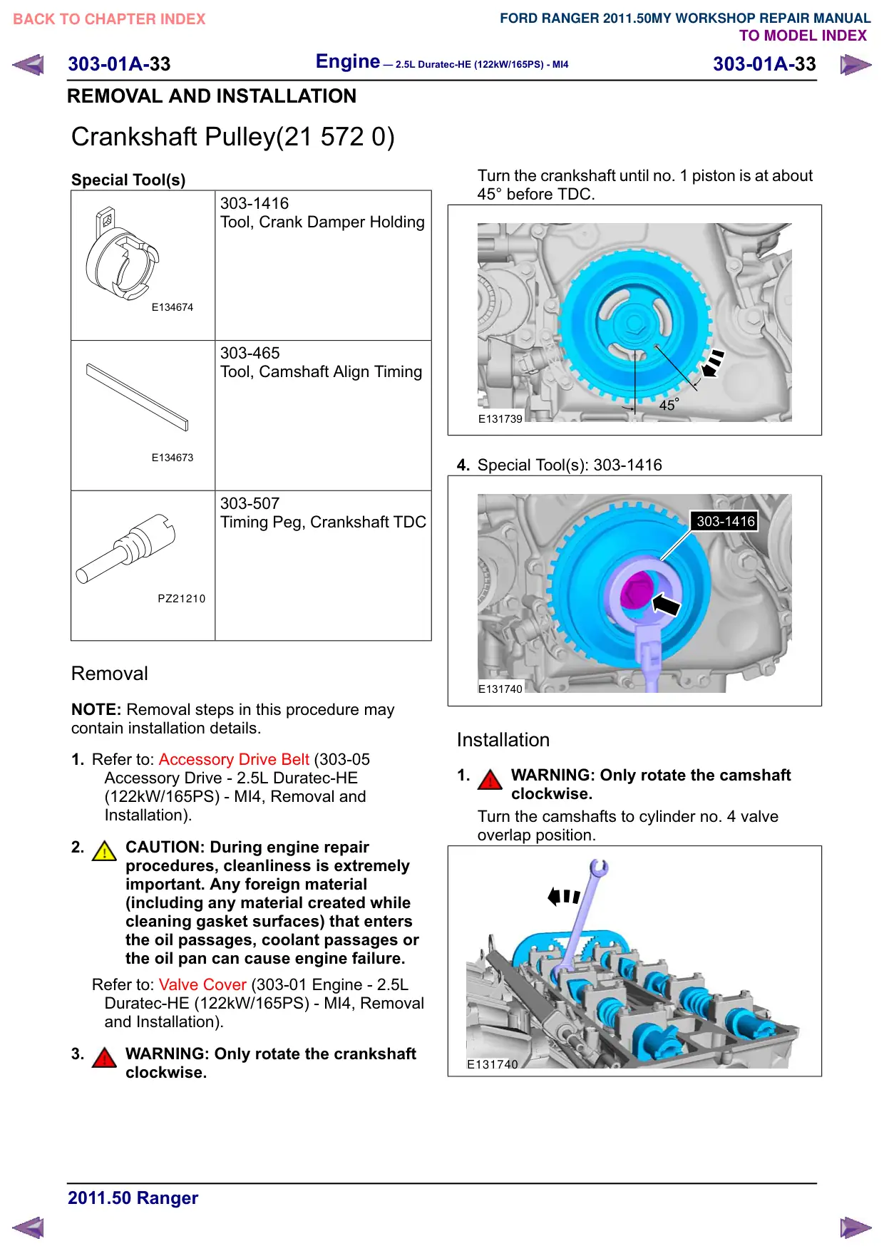
Turn the crankshaft until no. 1 piston is at about
45° before TDC.
E131739
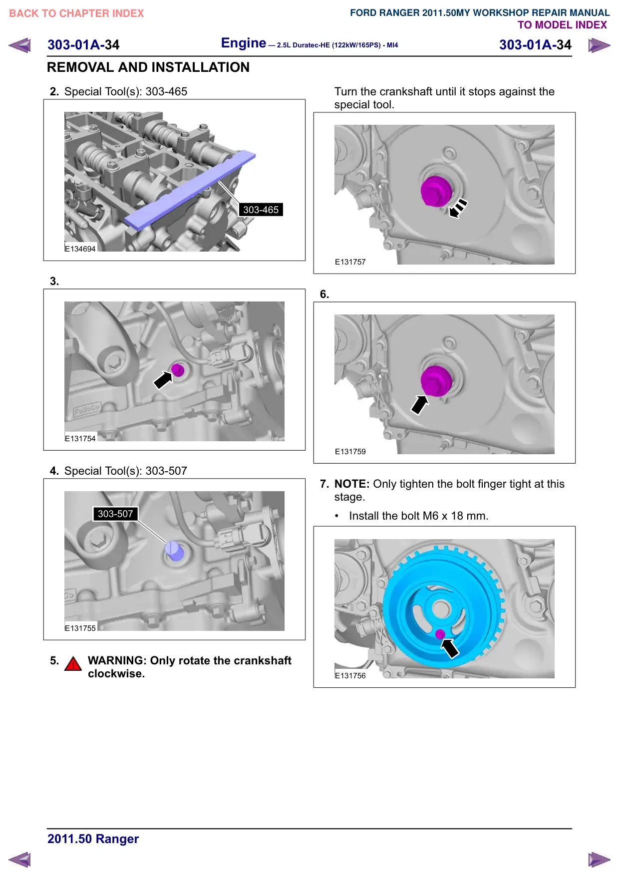
4. Special Tool(s): 303-1416
303-1416
E131740
Installation
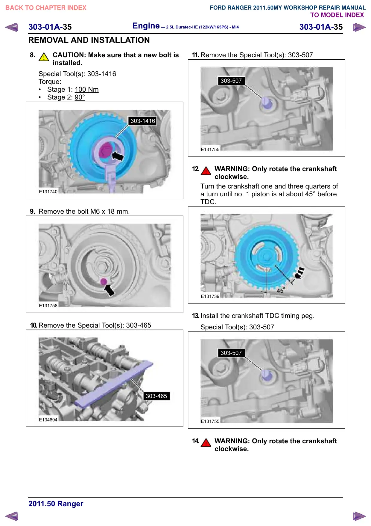
1.
WARNING: Only rotate the camshaft
clockwise.
Turn the camshafts to cylinder no. 4 valve
overlap position.
E131740
Engine – 2.5L Duratec-HE (122kW/165PS) - MI4
303-01A-34
303-01A-34
REMOVAL AND INSTALLATION
2. Special Tool(s): 303-465
303-465
E134694
3.
E131754
4. Special Tool(s): 303-507
303-507
E131755
5.
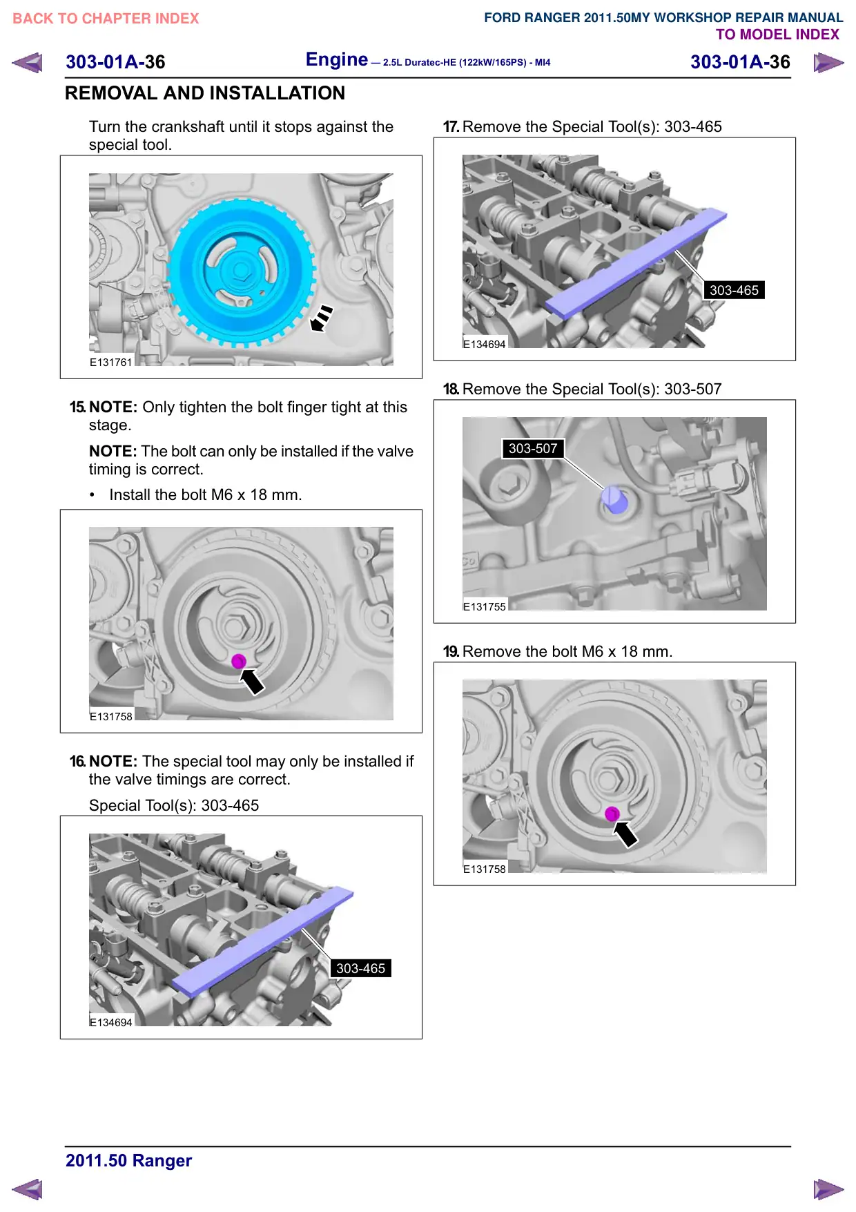
WARNING: Only rotate the crankshaft
clockwise.
Turn the crankshaft until it stops against the
special tool.
E131757
6.
E131759
7. NOTE: Only tighten the bolt finger tight at this
stage.
Install the bolt M6 x 18 mm.
E131756
303-01A-35
Engine – 2.5L Duratec-HE (122kW/165PS) - MI4
303-01A-35
REMOVAL AND INSTALLATION
8.
CAUTION: Make sure that a new bolt is
installed.
Special Tool(s): 303-1416
Torque:
Stage 1: 100
Nm
Stage 2: 90°
303-1416
E131740
9. Remove the bolt M6 x 18 mm.
E131758
10.Remove the Special Tool(s): 303-465
303-465
E134694
11. Remove the Special Tool(s): 303-507
303-507
E131755
12.
WARNING: Only rotate the crankshaft
clockwise.
Turn the crankshaft one and three quarters of
a turn until no. 1 piston is at about 45° before
TDC.
E131739
13.Install the crankshaft TDC timing peg.
Special Tool(s): 303-507
303-507
E131755
14.
WARNING: Only rotate the crankshaft
clockwise.
Engine – 2.5L Duratec-HE (122kW/165PS) - MI4
303-01A-36
303-01A-36
REMOVAL AND INSTALLATION
Turn the crankshaft until it stops against the
special tool.
E131761
15.NOTE: Only tighten the bolt finger tight at this
stage.
NOTE: The bolt can only be installed if the valve
timing is correct.
Install the bolt M6 x 18 mm.
E131758
16.NOTE: The special tool may only be installed if
the valve timings are correct.
Special Tool(s): 303-465
303-465
E134694
17.Remove the Special Tool(s): 303-465
303-465
E134694
18.Remove the Special Tool(s): 303-507
303-507
E131755
19.Remove the bolt M6 x 18 mm.
E131758
Engine – 2.5L Duratec-HE (122kW/165PS) - MI4
303-01A-39
303-01A-39
REMOVAL AND INSTALLATION
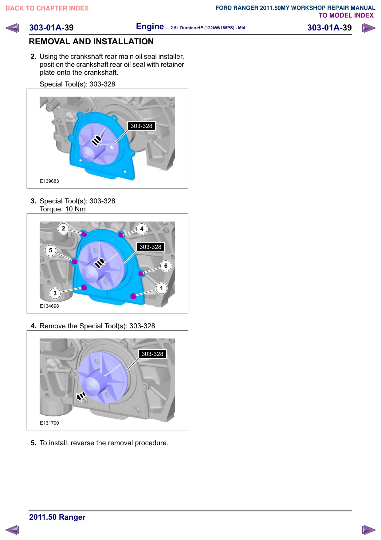
2. Using the crankshaft rear main oil seal installer,
position the crankshaft rear oil seal with retainer
plate onto the crankshaft.
Special Tool(s): 303-328
303-328
E139683
3. Special Tool(s): 303-328
Torque: 10 Nm
2
4
303-328
5
6
1
3
E134698
4. Remove the Special Tool(s): 303-328
303-328
E131790
5. To install, reverse the removal procedure.
Engine – 2.5L Duratec-HE (122kW/165PS) - MI4
303-01A-40
303-01A-40
REMOVAL AND INSTALLATION
Cylinder Head(21 163 0)
Materials
Name
Specification
Hypoid Oil 85W-90
SQ-M2C9002-AA /
A72SX-19K261-CA
Removal
NOTE: Removal steps in this procedure may
contain installation details.
1. Refer to: Cooling System Draining, Filling and
Bleeding (303-03 Engine Cooling, General
Procedures).
2. Refer to: Timing Chain (303-01 Engine - 2.5L
Duratec-HE (122kW/165PS) - MI4, Removal
and Installation).
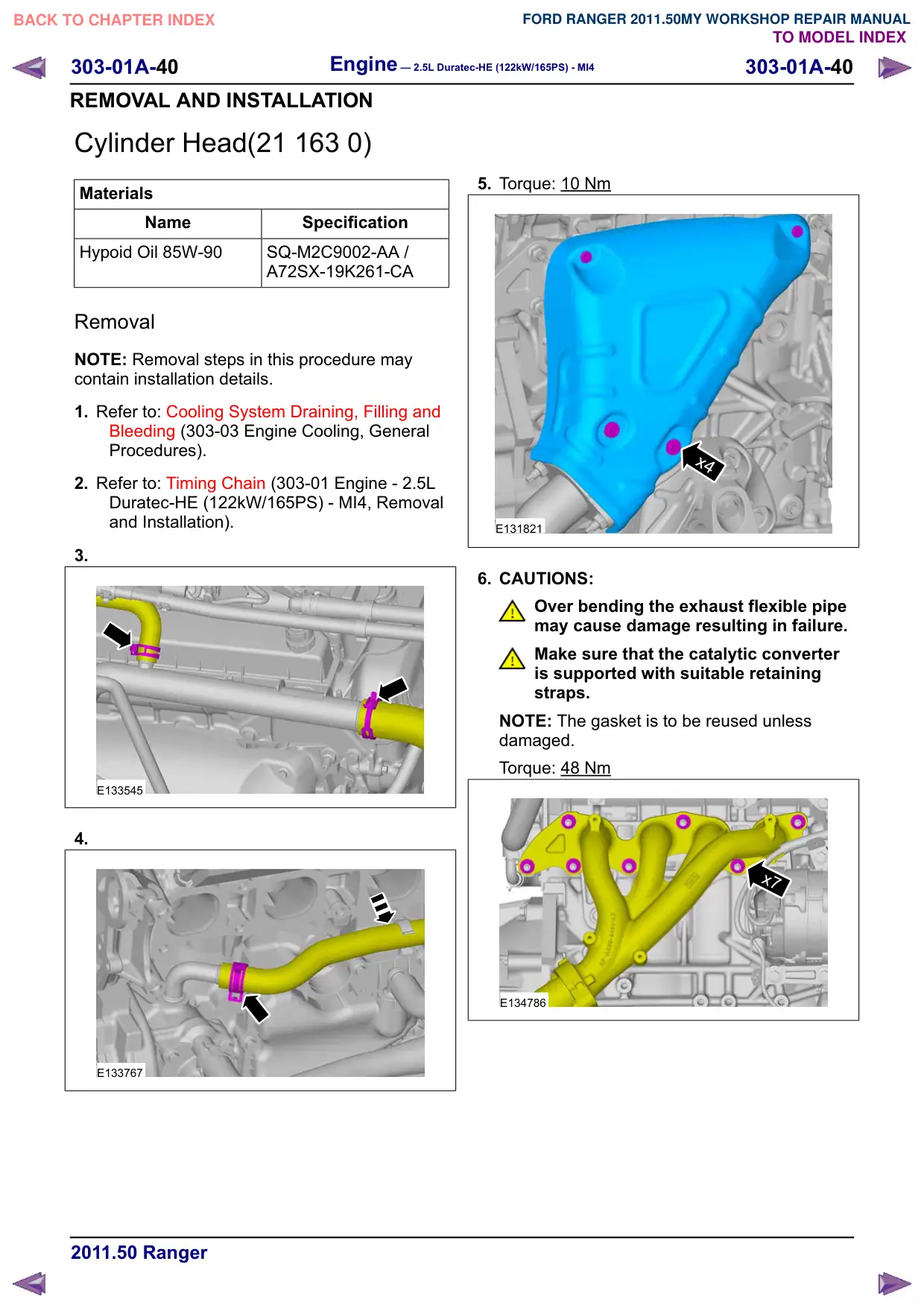
3.
E133545
4.
E133767
5. Torque: 10 Nm
x4
E131821
6. CAUTIONS:
Over bending the exhaust flexible pipe
may cause damage resulting in failure.
Make sure that the catalytic converter
is supported with suitable retaining
straps.
NOTE: The gasket is to be reused unless
damaged.
Torque: 48 Nm
x7
E134786
Engine – 2.5L Duratec-HE (122kW/165PS) - MI4
303-01A-41
303-01A-41
REMOVAL AND INSTALLATION
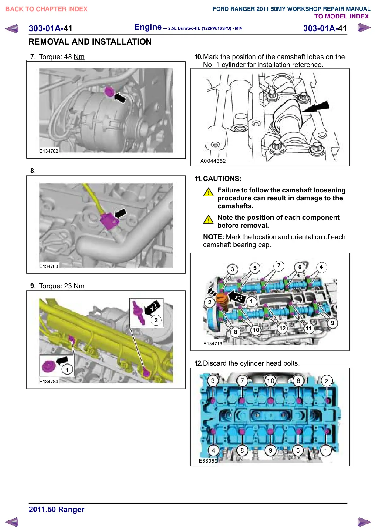
7. Torque: 48 Nm
E134782
8.
E134783
9. Torque: 23 Nm
x2
2
1
E134784
10.Mark the position of the camshaft lobes on the
No. 1 cylinder for installation reference.
A0044352
11. CAUTIONS:
Failure to follow the camshaft loosening
procedure can result in damage to the
camshafts.
Note the position of each component
before removal.
NOTE: Mark the location and orientation of each
camshaft bearing cap.
7
4
5
6
3
x2
2
1
12
11
10
8
E134716
12.Discard the cylinder head bolts.
3
7
10
6
2
4
8
9
5
1
E68059
303-01A-44
Engine – 2.5L Duratec-HE (122kW/165PS) - MI4
303-01A-44
REMOVAL AND INSTALLATION
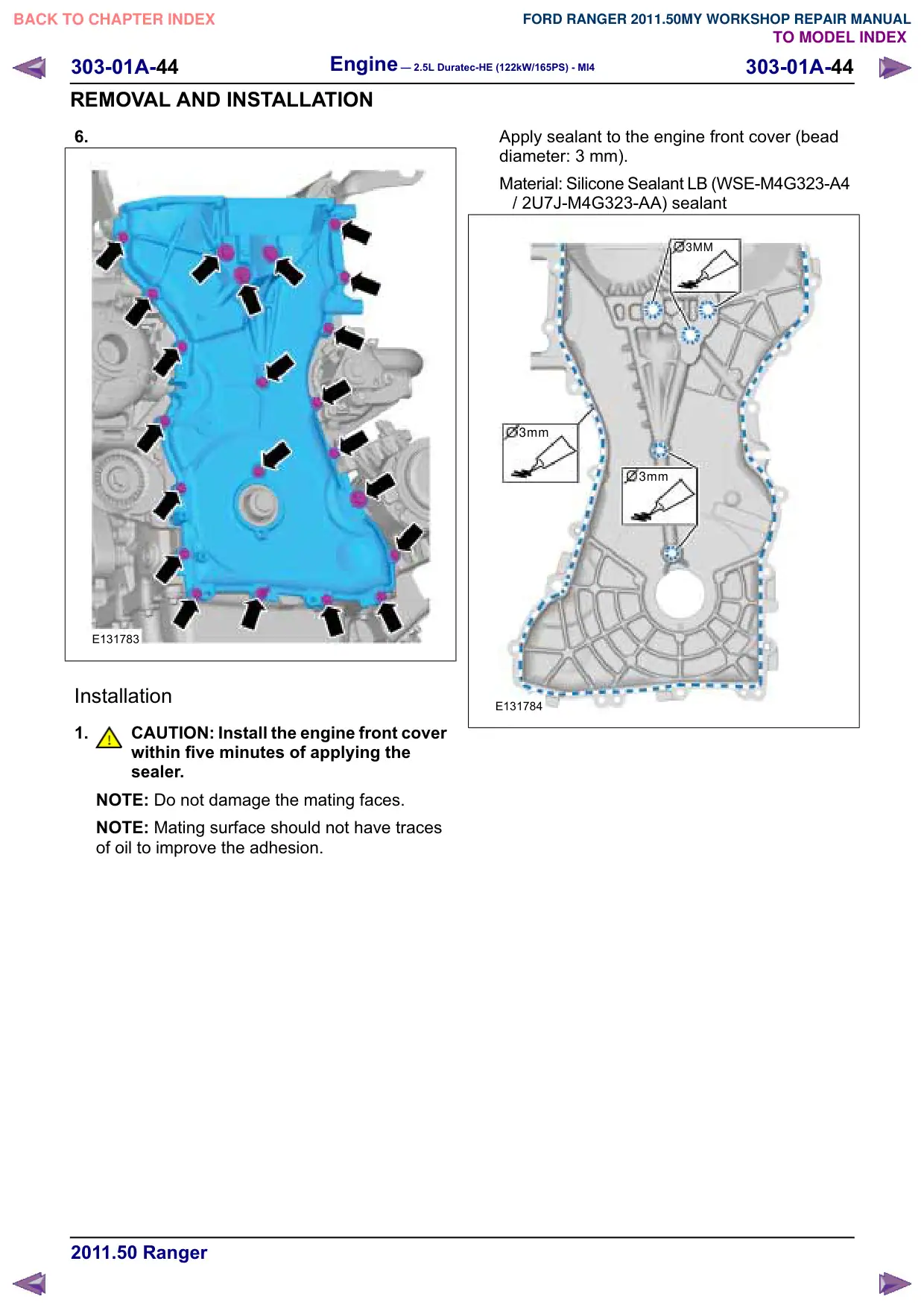
6.
E131783
Installation
1.
CAUTION: Install the engine front cover
within five minutes of applying the
sealer.
NOTE: Do not damage the mating faces.
NOTE: Mating surface should not have traces
of oil to improve the adhesion.
Apply sealant to the engine front cover (bead
diameter: 3 mm).
Material: Silicone Sealant LB (WSE-M4G323-A4
/ 2U7J-M4G323-AA) sealant
3MM
3mm
3mm
E131784
Engine – 2.5L Duratec-HE (122kW/165PS) - MI4
303-01A-48
303-01A-48
REMOVAL AND INSTALLATION
Intake Manifold(21 183 0)
Removal
NOTE: Removal steps in this procedure may
contain installation details.
1. WARNINGS:
Do not smoke, carry lighted tobacco or
have an open flame of any type when
working on or near any fuel-related
component. Highly flammable mixtures
are always present and may be ignited.
Failure to follow these instructions may
result in serious personal injury.
Do not carry personal electronic devices
such as cell phones, pagers or audio
equipment of any type when working on
or near any fuel-related component.
Highly flammable mixtures are always
present and may be ignited. Failure to
follow these instructions may result in
serious personal injury.
Always disconnect the battery ground
cable at the battery when working on an
evaporative emission (EVAP) system or
fuel-related component. Highly
flammable mixtures are always present
and may be ignited. Failure to follow
these instructions may result in serious
personal injury.
Refer to: Battery Disconnect and Connect
(414-01 Battery, Mounting and Cables,
General Procedures).
2. Refer to: Lifting (100-02 Jacking and Lifting,
Description and Operation).
3. Refer to: Throttle Body (303-04 Fuel Charging
and Controls - 2.5L Duratec-HE
(122kW/165PS) - MI4, Removal and
Installation).
4. Refer to: Fuel System Pressure Release
(310-00 Fuel System - General Information -
2.5L Duratec-HE (122kW/165PS) - MI4,
General Procedures).
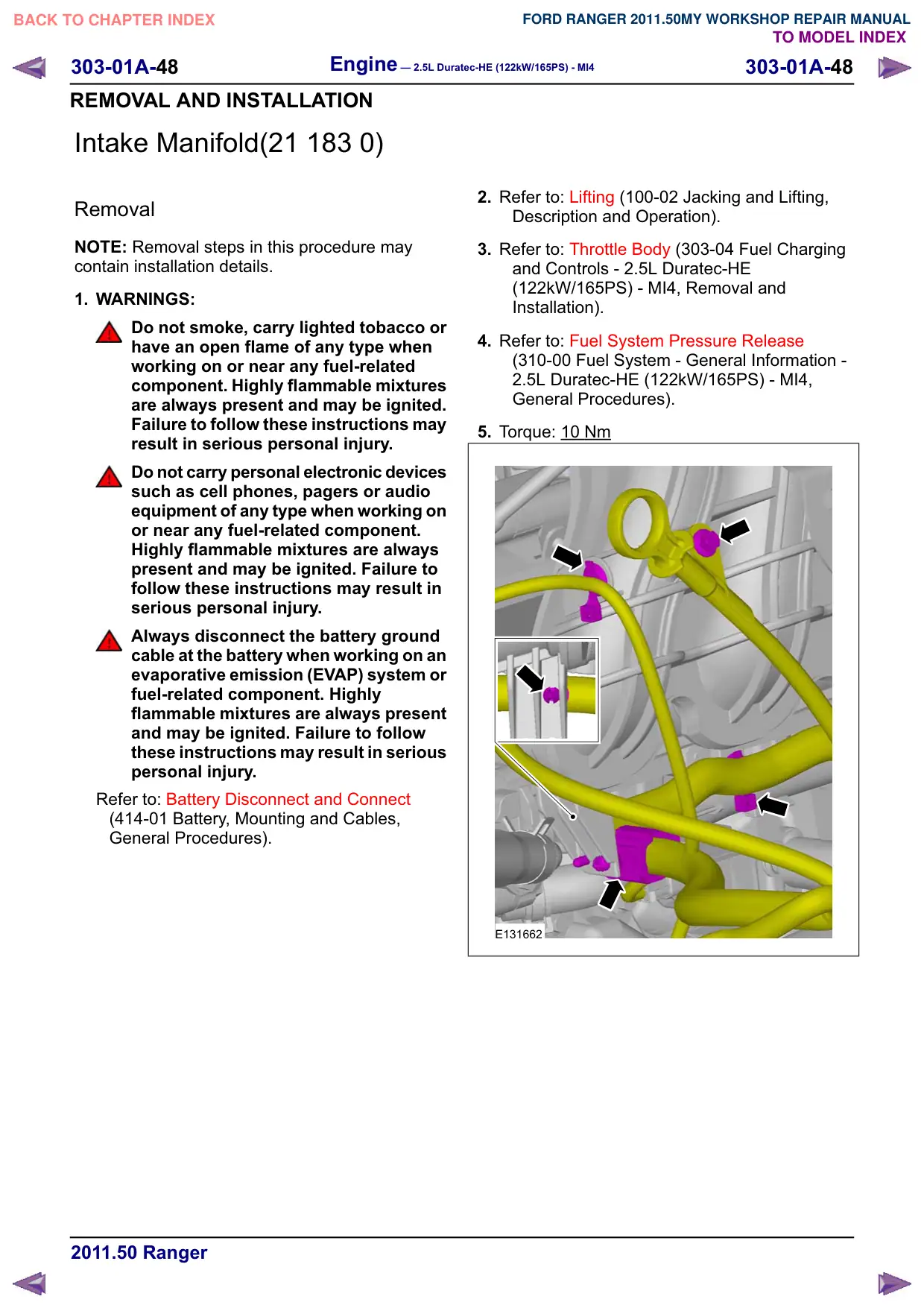
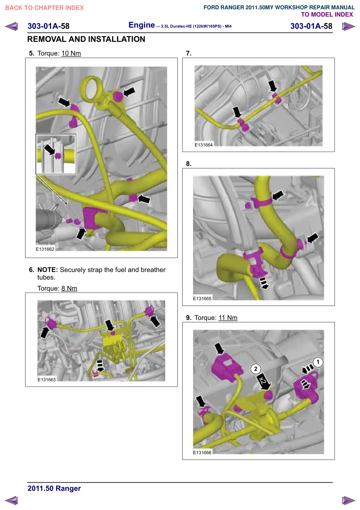
5. Torque: 10 Nm
E131662
303-01A-49
Engine – 2.5L Duratec-HE (122kW/165PS) - MI4
303-01A-49
REMOVAL AND INSTALLATION
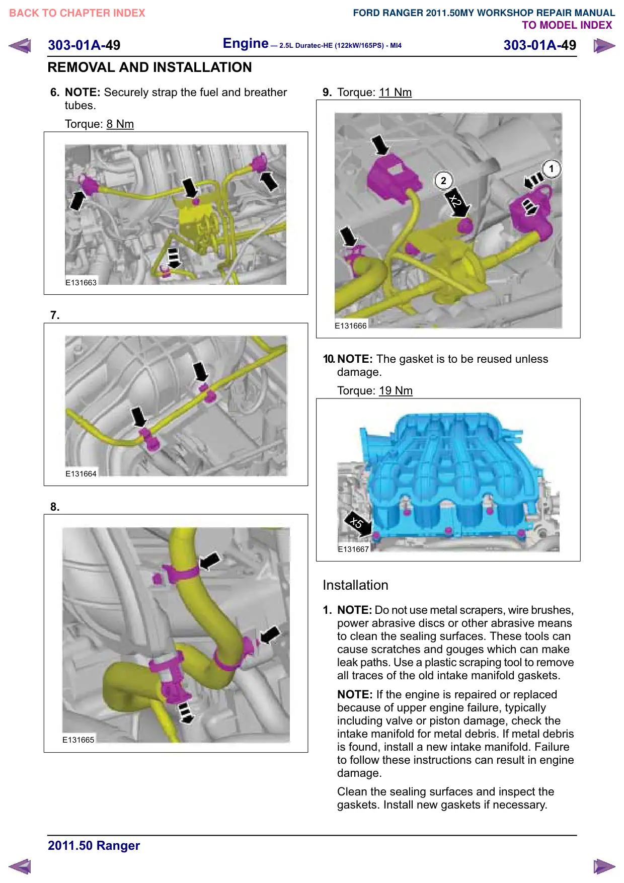
6. NOTE: Securely strap the fuel and breather
tubes.
Torque: 8
Nm
E131663
7.
E131664
8.
E131665
9. Torque: 11 Nm
1
2
x2
E131666
10.NOTE: The gasket is to be reused unless
damage.
Torque: 19 Nm
x5
E131667
Installation
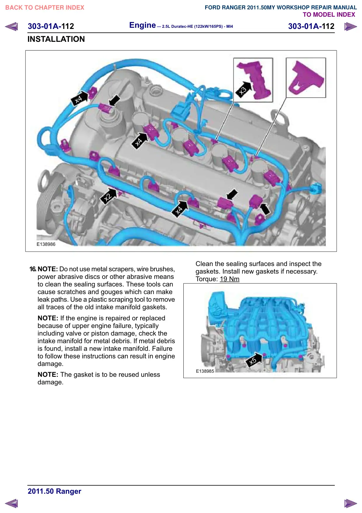
1. NOTE: Do not use metal scrapers, wire brushes,
power abrasive discs or other abrasive means
to clean the sealing surfaces. These tools can
cause scratches and gouges which can make
leak paths. Use a plastic scraping tool to remove
all traces of the old intake manifold gaskets.
NOTE: If the engine is repaired or replaced
because of upper engine failure, typically
including valve or piston damage, check the
intake manifold for metal debris. If metal debris
is found, install a new intake manifold. Failure
to follow these instructions can result in engine
damage.
Clean the sealing surfaces and inspect the
gaskets. Install new gaskets if necessary.
Engine – 2.5L Duratec-HE (122kW/165PS) - MI4
303-01A-50
303-01A-50
REMOVAL AND INSTALLATION
2. To install, reverse the removal procedure.
3. NOTE: Make sure that the pedals remain in the
rest position.
Turn the ignition key to position II and then wait
one minute in order to initialise the throttle valve.
4. Turn the ignition key to the OFF position.
Engine – 2.5L Duratec-HE (122kW/165PS) - MI4
303-01A-53
303-01A-53
REMOVAL AND INSTALLATION
Oil Pan(21 154 0)
Special Tool(s)
303-428
Separator, Oil Pan
21179
Materials
Name
Specification
Silicone Sealant LB
WSE-M4G323-A4 /
2U7J-M4G323-AA
Removal
NOTE: Removal steps in this procedure may
contain installation details.
1. Refer to: Health and Safety Precautions (100-00
General Information, Description and
Operation).
2. Refer to: Lifting (100-02 Jacking and Lifting,
Description and Operation).
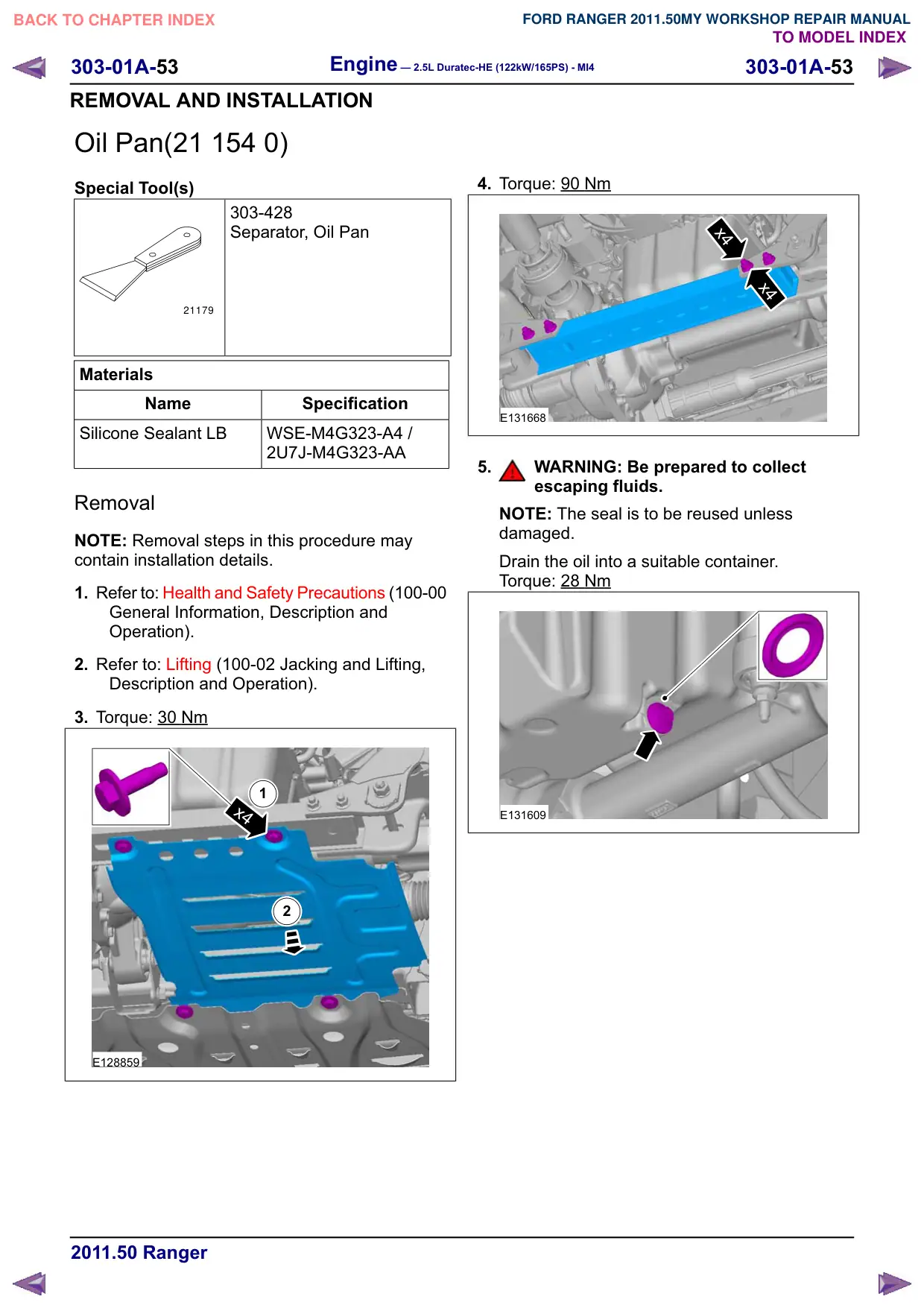
3. Torque: 30 Nm
1
x4
2
E128859
4. Torque: 90 Nm
x4
x4
E131668
5.
WARNING: Be prepared to collect
escaping fluids.
NOTE: The seal is to be reused unless
damaged.
Drain the oil into a suitable container.
Torque: 28 Nm
E131609
Engine – 2.5L Duratec-HE (122kW/165PS) - MI4
303-01A-54
303-01A-54
REMOVAL AND INSTALLATION
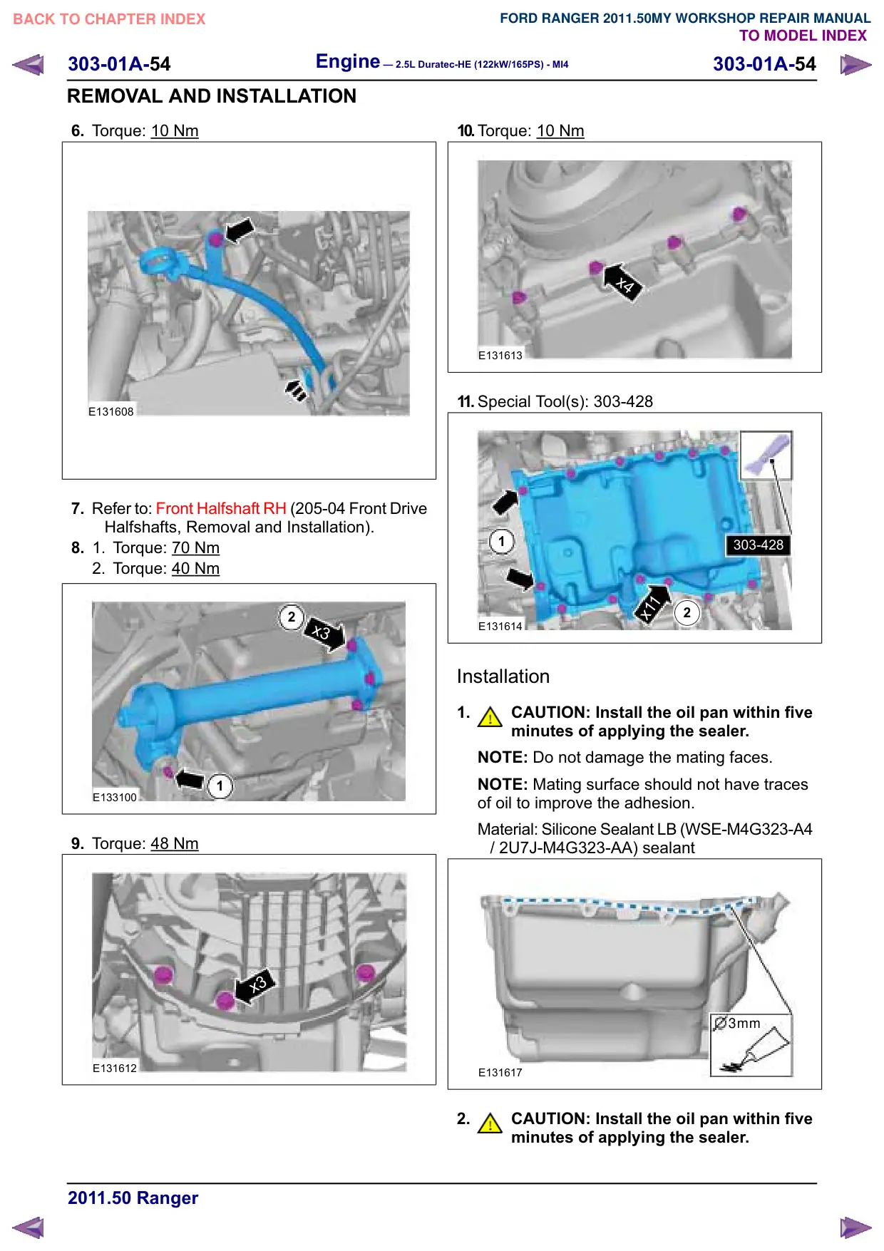
6. Torque: 10
Nm
E131608
7. Refer to: Front Halfshaft RH (205-04 Front Drive
Halfshafts, Removal and Installation).
8.
1.
Torque: 70
Nm
2. Torque: 40 Nm
2
x3
1
E133100
9. Torque: 48 Nm
x3
E131612
10.Torque: 10 Nm
x4
E131613
11. Special Tool(s): 303-428
1
303-428
x11
2
E131614
Installation
1.
CAUTION: Install the oil pan within five
minutes of applying the sealer.
NOTE: Do not damage the mating faces.
NOTE: Mating surface should not have traces
of oil to improve the adhesion.
Material: Silicone Sealant LB (WSE-M4G323-A4
/ 2U7J-M4G323-AA) sealant
3mm
E131617
2.
CAUTION: Install the oil pan within five
minutes of applying the sealer.
Engine – 2.5L Duratec-HE (122kW/165PS) - MI4
303-01A-55
303-01A-55
REMOVAL AND INSTALLATION
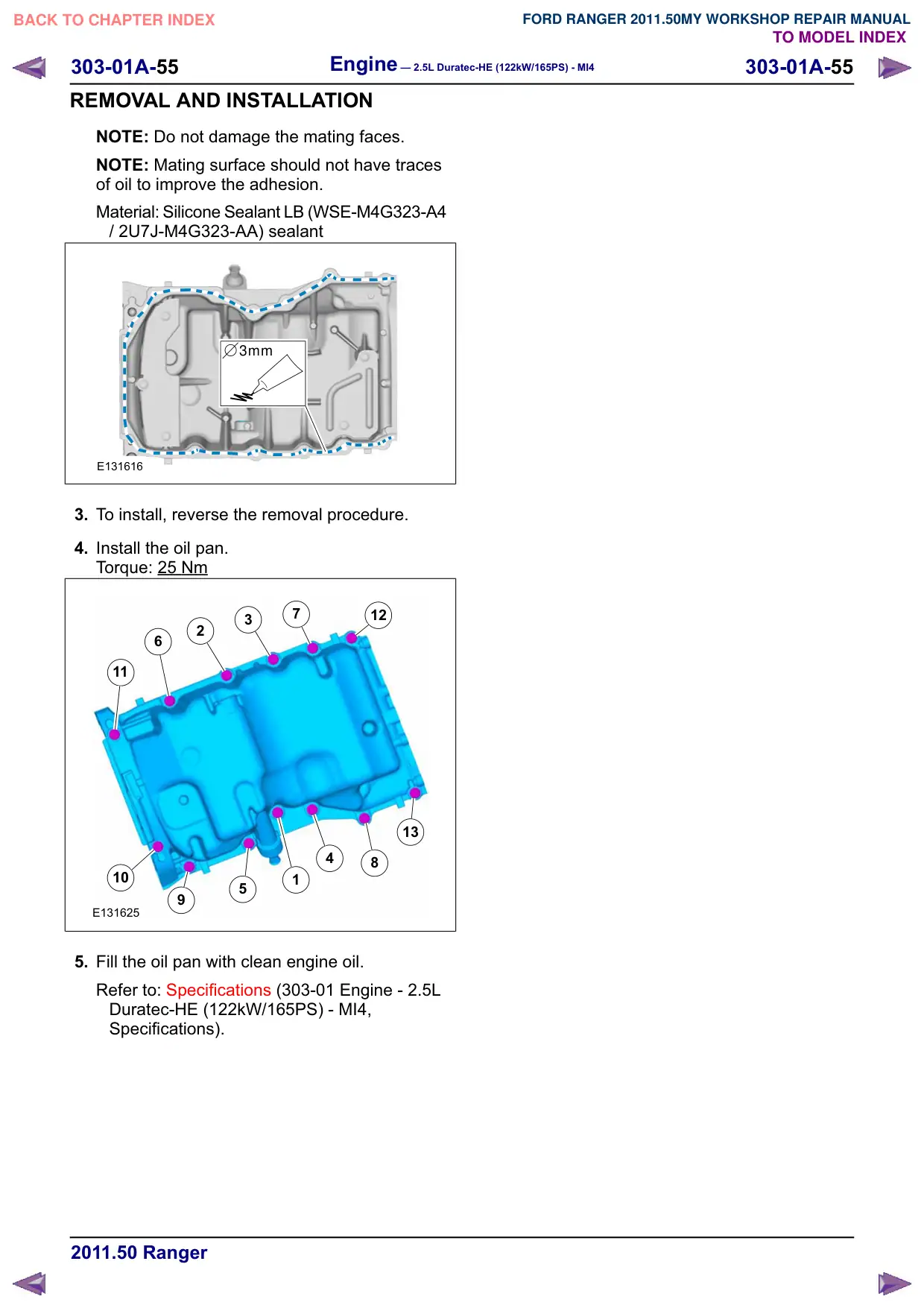
NOTE: Do not damage the mating faces.
NOTE: Mating surface should not have traces
of oil to improve the adhesion.
Material: Silicone Sealant LB (WSE-M4G323-A4
/ 2U7J-M4G323-AA) sealant
3mm
E131616
3. To install, reverse the removal procedure.
4. Install the oil pan.
Torque: 25 Nm
7
12
3
2
6
11
13
4
8
10
1
5
E131625
5. Fill the oil pan with clean engine oil.
Refer to: Specifications (303-01 Engine - 2.5L
Duratec-HE (122kW/165PS) - MI4,
Specifications).
Engine – 2.5L Duratec-HE (122kW/165PS) - MI4
303-01A-57
303-01A-57
REMOVAL AND INSTALLATION
Valve Cover(21 141 0)
Materials
Name
Specification
Silicone Sealant LB
WSE-M4G323-A4 /
2U7J-M4G323-AA
Removal
NOTE: Removal steps in this procedure may
contain installation details.
1. WARNINGS:
Do not smoke, carry lighted tobacco or
have an open flame of any type when
working on or near any fuel-related
component. Highly flammable mixtures
are always present and may be ignited.
Failure to follow these instructions may
result in serious personal injury.
Do not carry personal electronic devices
such as cell phones, pagers or audio
equipment of any type when working on
or near any fuel-related component.
Highly flammable mixtures are always
present and may be ignited. Failure to
follow these instructions may result in
serious personal injury.
Always disconnect the battery ground
cable at the battery when working on an
evaporative emission (EVAP) system or
fuel-related component. Highly
flammable mixtures are always present
and may be ignited. Failure to follow
these instructions may result in serious
personal injury.
Refer to: Battery Disconnect and Connect
(414-01 Battery, Mounting and Cables,
General Procedures).
2. Refer to: Lifting (100-02 Jacking and Lifting,
Description and Operation).
3. Refer to: Fuel System Pressure Release
(310-00 Fuel System - General Information -
2.5L Duratec-HE (122kW/165PS) - MI4,
General Procedures).
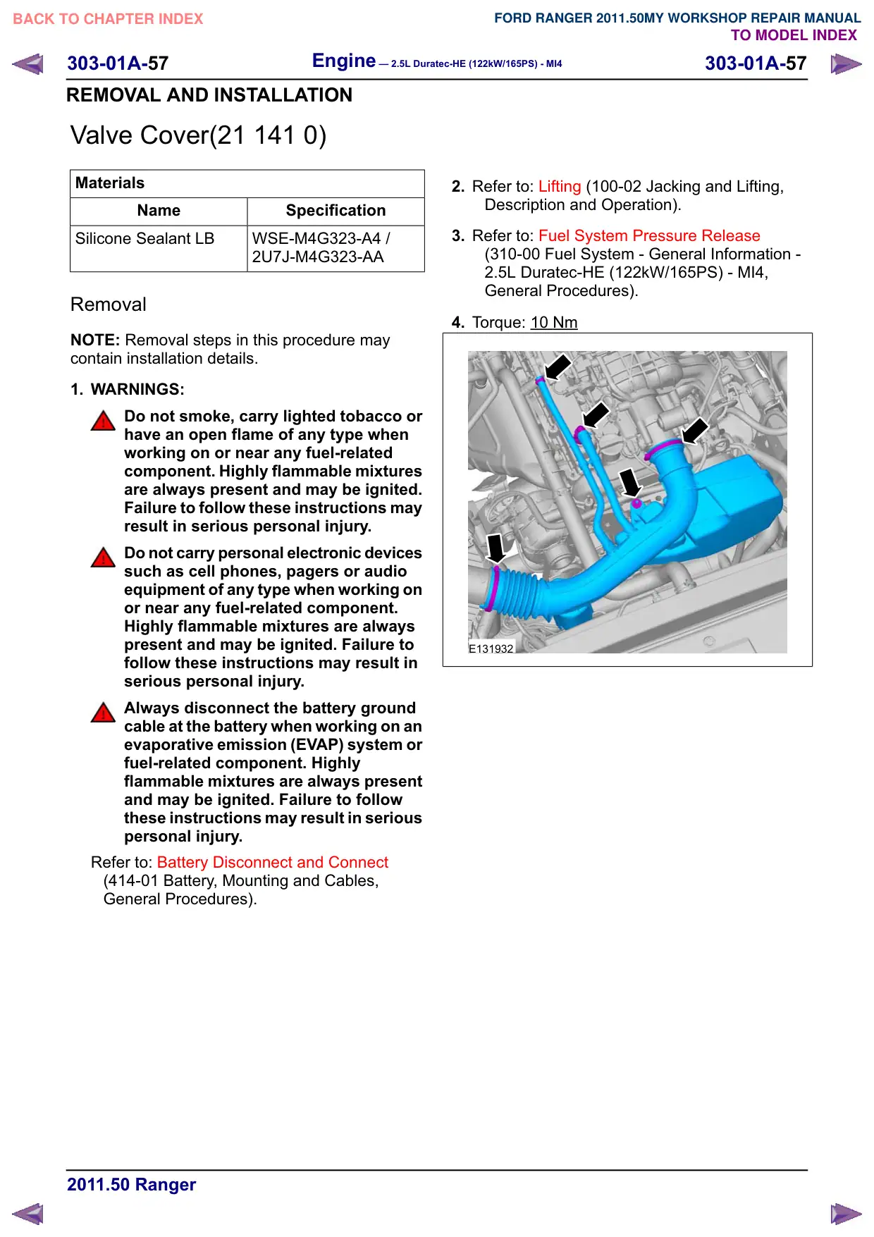
4. Torque: 10 Nm
E131932
303-01A-59
Engine – 2.5L Duratec-HE (122kW/165PS) - MI4
303-01A-59
REMOVAL AND INSTALLATION
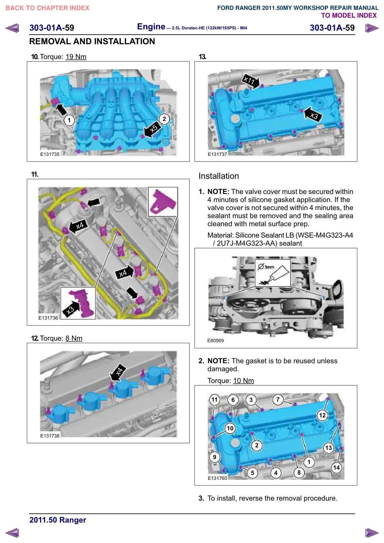
10.Torque: 19 Nm
2
1
x5
E131735
11.
x4
x4
x3
E131736
12.Torque: 8 Nm
x4
E131738
13.
x11
x3
E131737
Installation
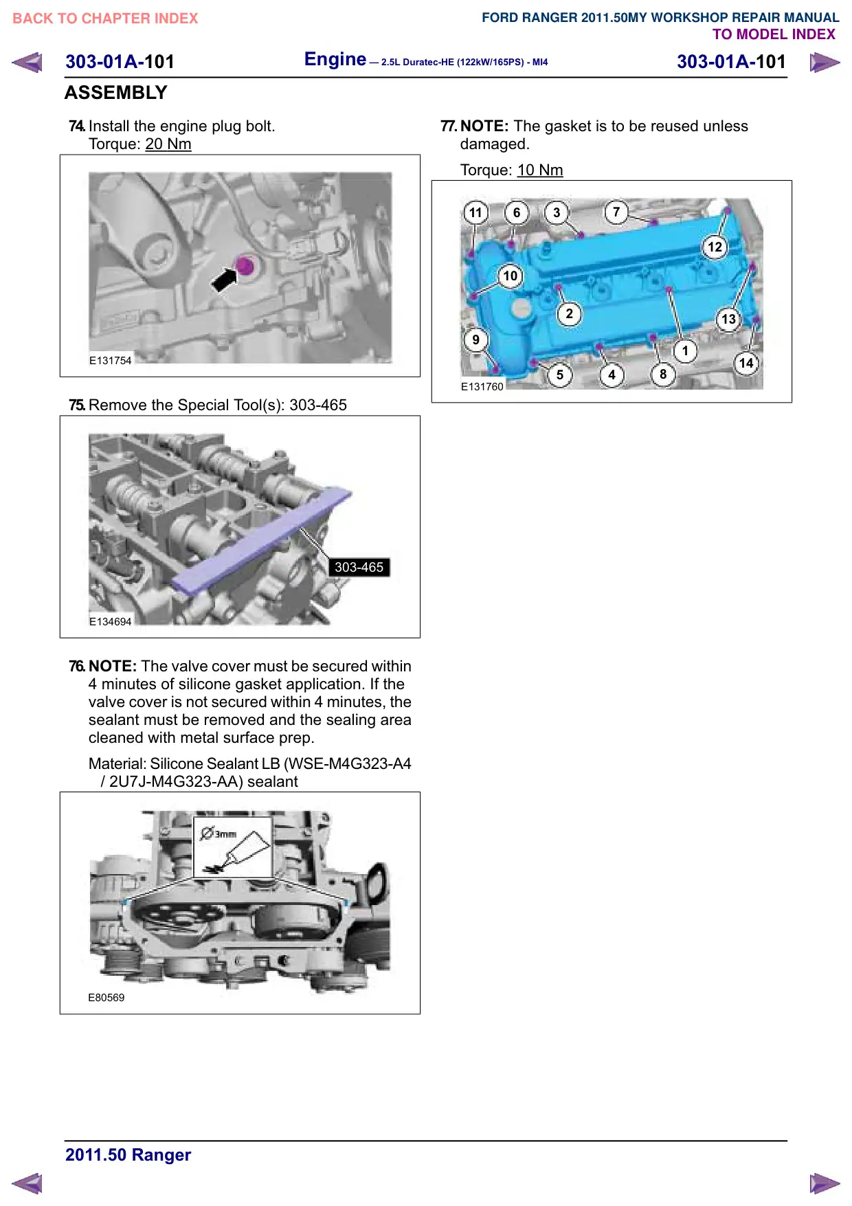
1. NOTE: The valve cover must be secured within
4 minutes of silicone gasket application. If the
valve cover is not secured within 4 minutes, the
sealant must be removed and the sealing area
cleaned with metal surface prep.
Material: Silicone Sealant LB (WSE-M4G323-A4
/ 2U7J-M4G323-AA) sealant
E80569
2. NOTE: The gasket is to be reused unless
damaged.
Torque: 10
Nm
11
6
3
7
12
10
2
13
1
14
5
4
8
E131760
3. To install, reverse the removal procedure.
Engine – 2.5L Duratec-HE (122kW/165PS) - MI4
303-01A-61
303-01A-61
REMOVAL
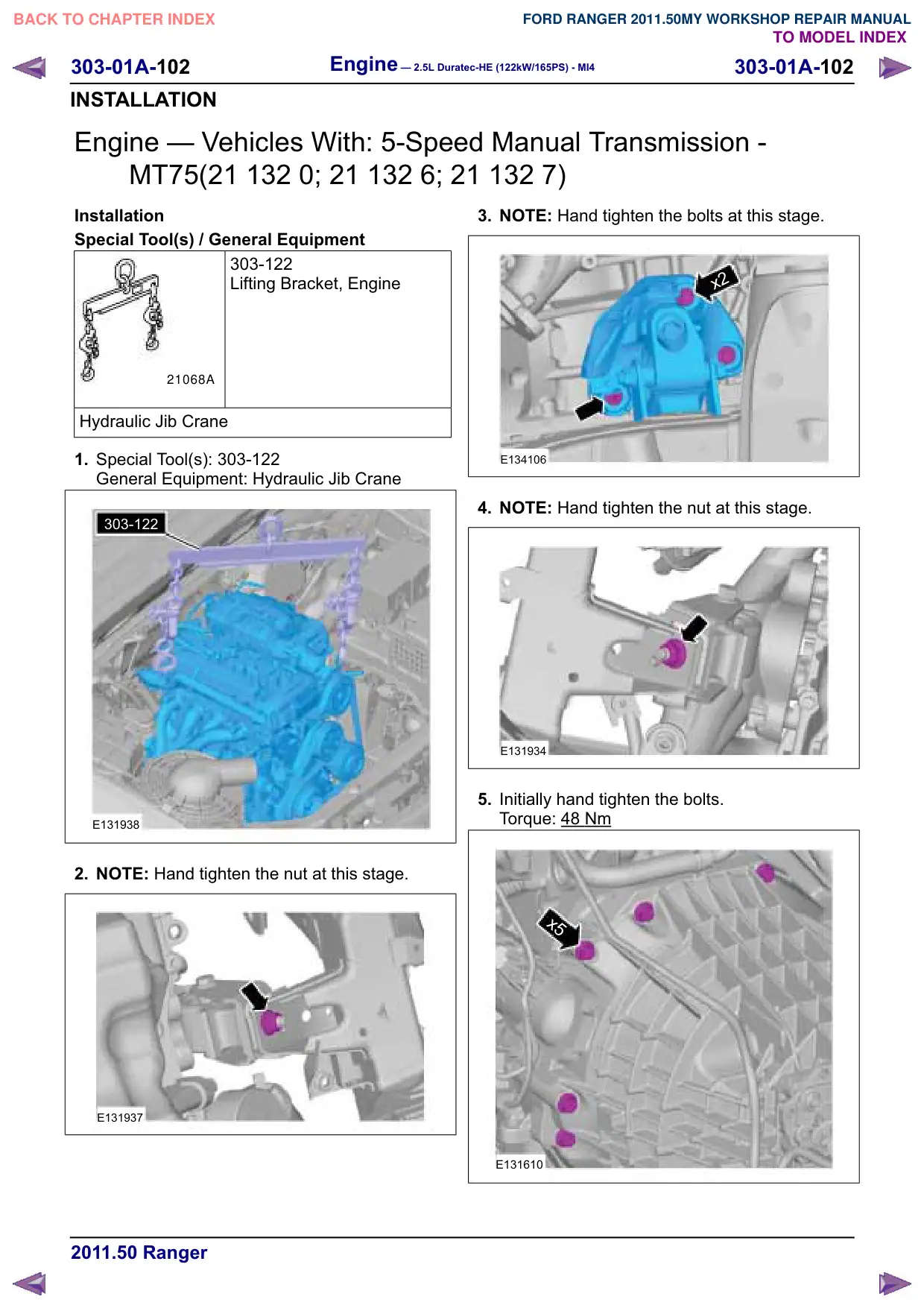
Engine – Vehicles With: 5-Speed Manual Transmission -
MT75(21 132 0; 21 132 6; 21 132 7)
Removal
Special Tool(s) / General Equipment
303-122
Lifting Bracket, Engine
21068A
Hydraulic Jib Crane
Transmission Jack
1. Refer to: Cooling System Draining, Filling and
Bleeding (303-03 Engine Cooling, General
Procedures).
2. Refer to: Battery Disconnect and Connect
(414-01 Battery, Mounting and Cables,
General Procedures).
3. Refer to: Lifting (100-02 Jacking and Lifting,
Description and Operation).
4. Refer to: Starter Motor (303-06 Starting System
- 2.5L Duratec-HE (122kW/165PS) - MI4,
Removal and Installation).
5. Refer to: Air Conditioning (A/C) System
Recovery, Evacuation and Charging (412-00
Climate Control System - General Information,
General Procedures).
6. Refer to: Brake System Health and Safety
Precautions (100-00 General Information,
Description and Operation).
7. Refer to: Fuel System Pressure Release
(310-00 Fuel System - General Information -
2.5L Duratec-HE (122kW/165PS) - MI4,
General Procedures).
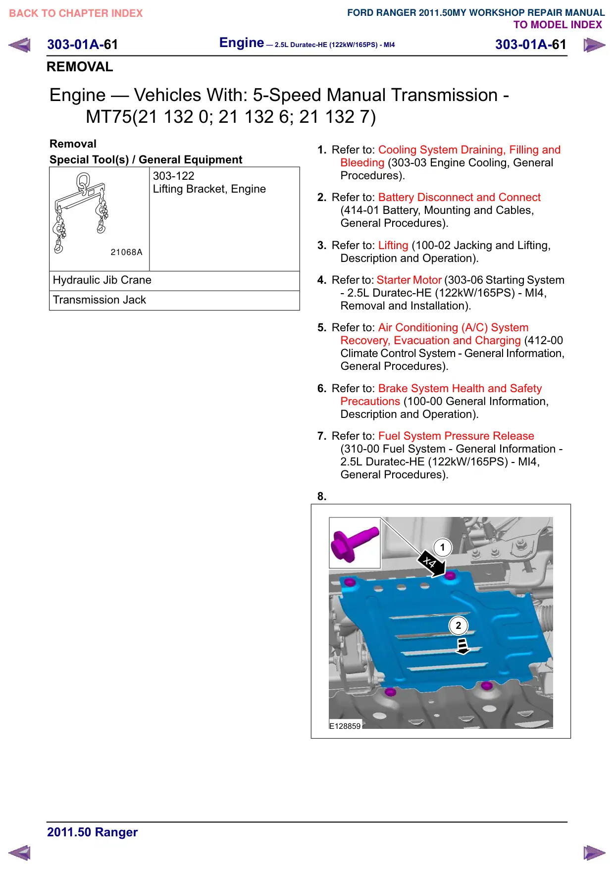
8.
1
x4
2
E128859
303-01A-65
Engine – 2.5L Duratec-HE (122kW/165PS) - MI4
303-01A-65
REMOVAL
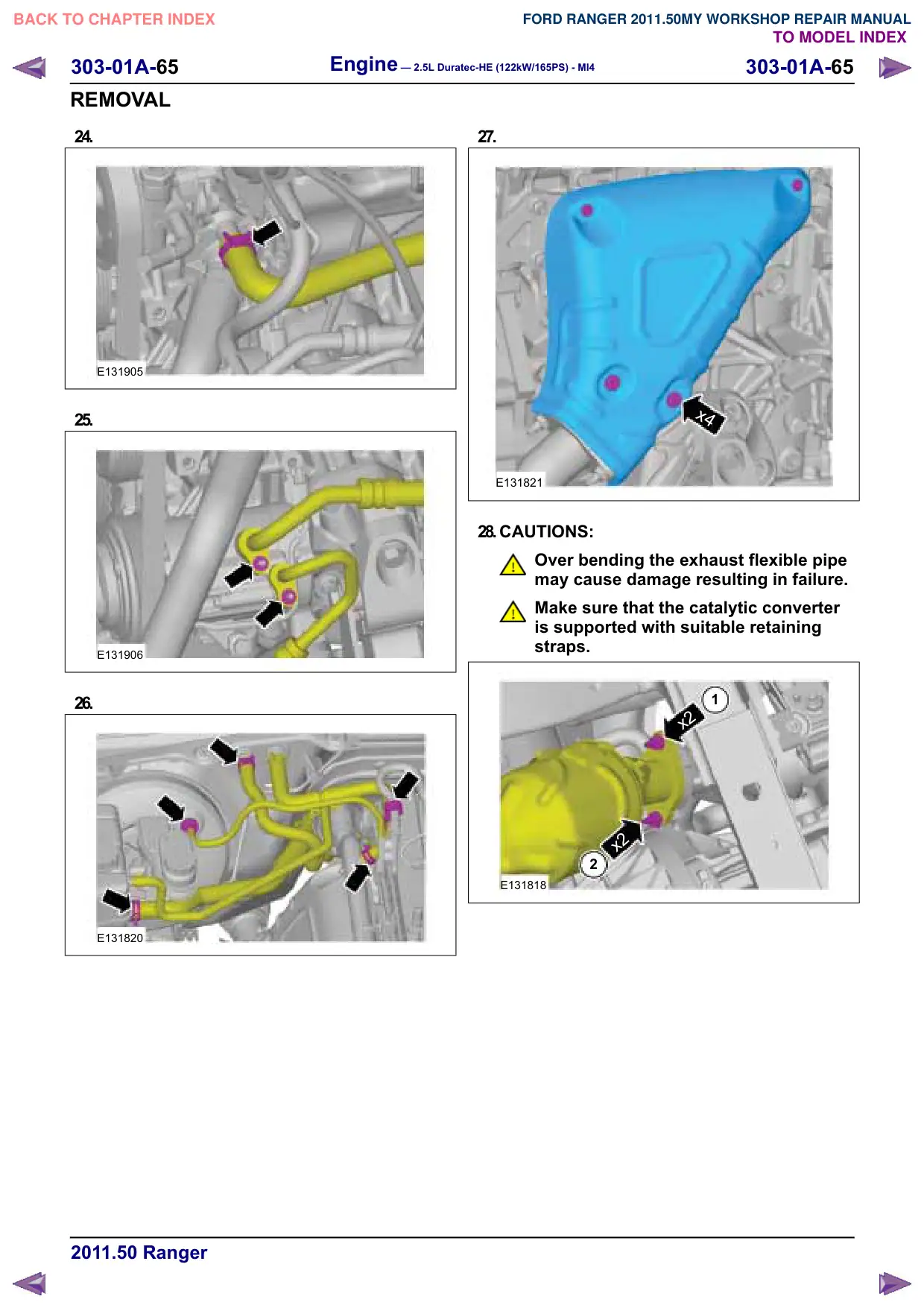
24.
E131905
25.
E131906
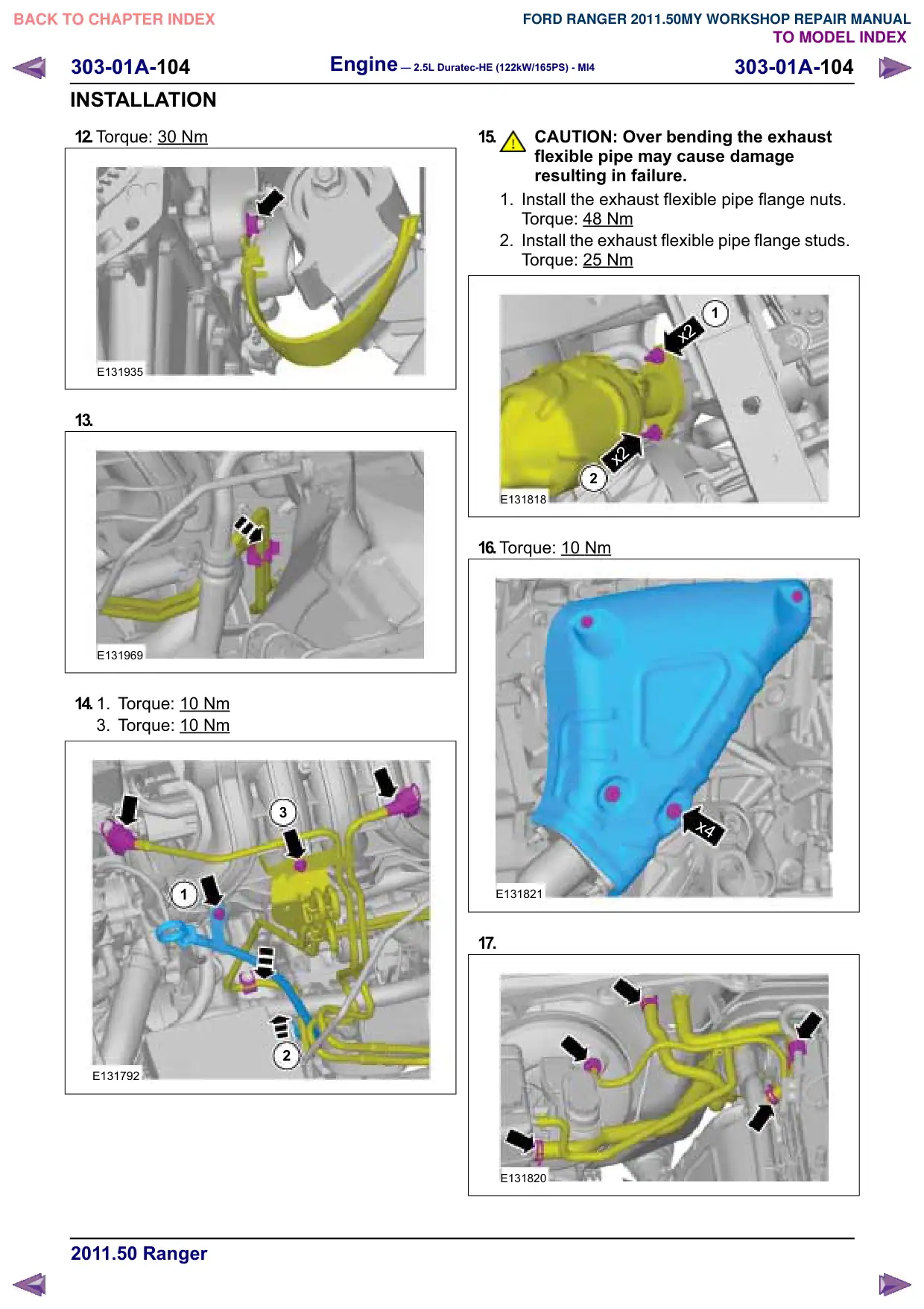
26.
E131820
27.
x4
E131821
28.CAUTIONS:
Over bending the exhaust flexible pipe
may cause damage resulting in failure.
Make sure that the catalytic converter
is supported with suitable retaining
straps.
1
x2
x2
2
E131818
303-01A-66
Engine – 2.5L Duratec-HE (122kW/165PS) - MI4
303-01A-66
REMOVAL
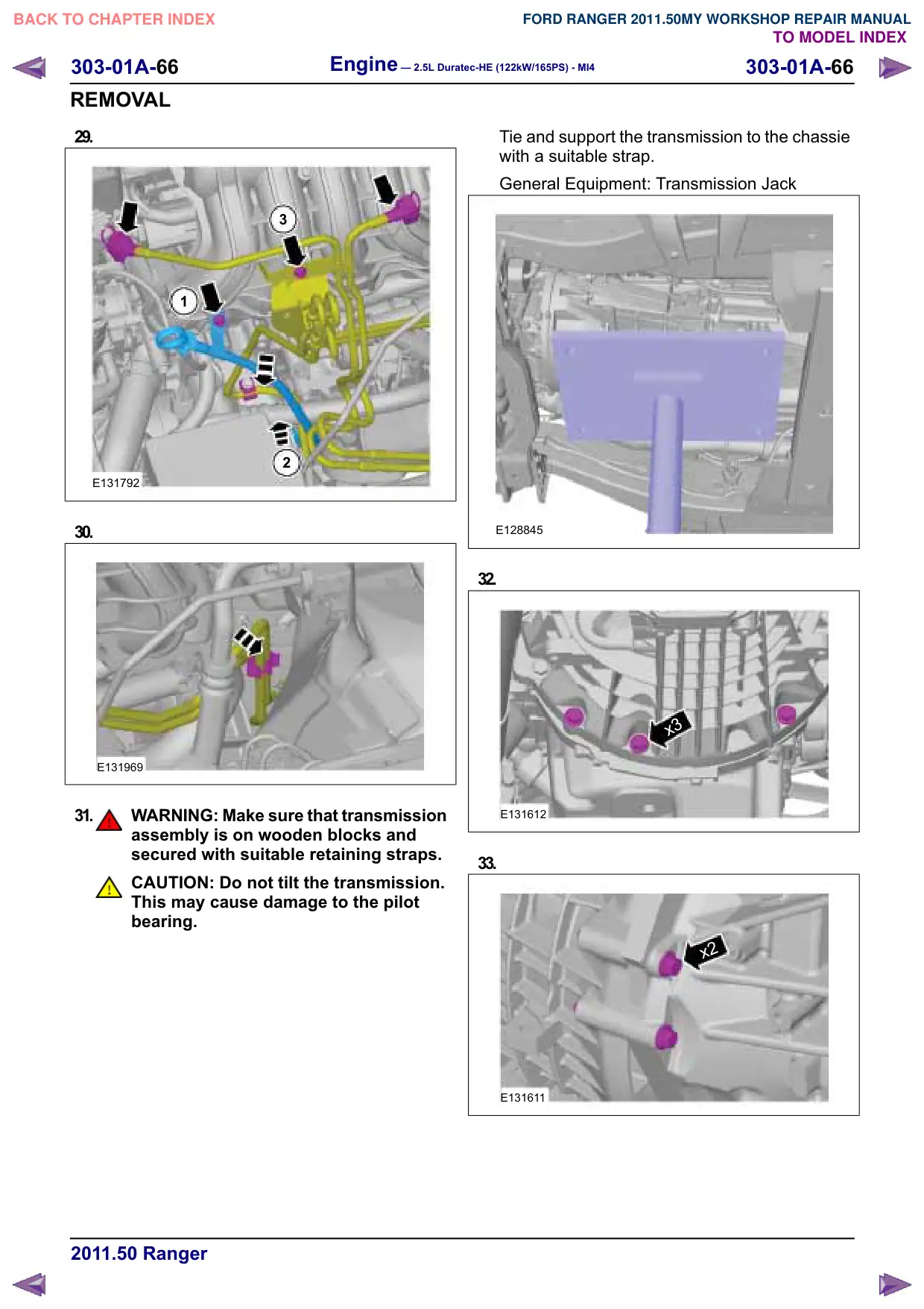
29.
3
1
2
E131792
30.
E131969
31.
WARNING: Make sure that transmission
assembly is on wooden blocks and
secured with suitable retaining straps.
CAUTION: Do not tilt the transmission.
This may cause damage to the pilot
bearing.
Tie and support the transmission to the chassie
with a suitable strap.
General Equipment: Transmission Jack
E128845
32.
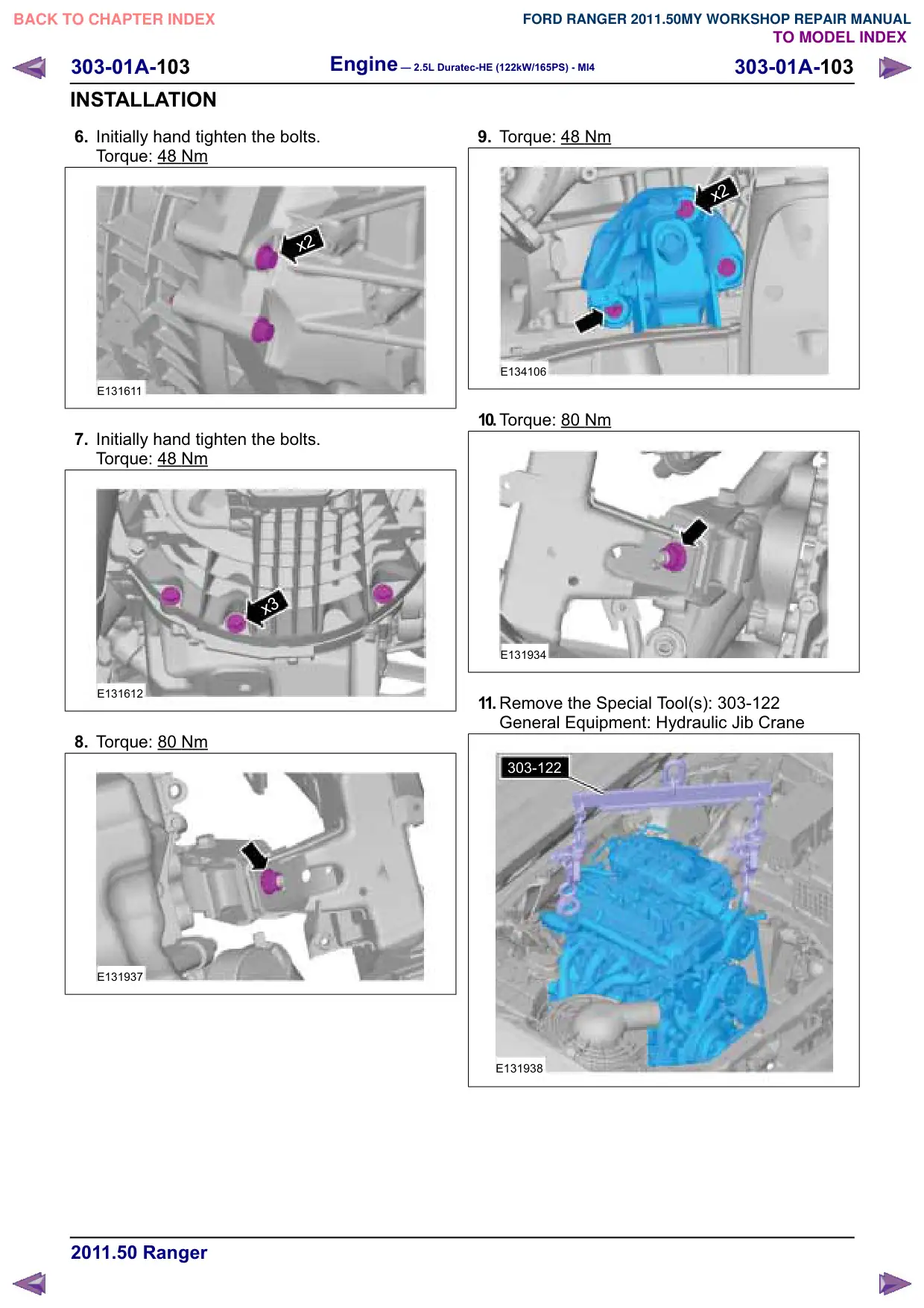
x3
E131612
33.
x2
E131611
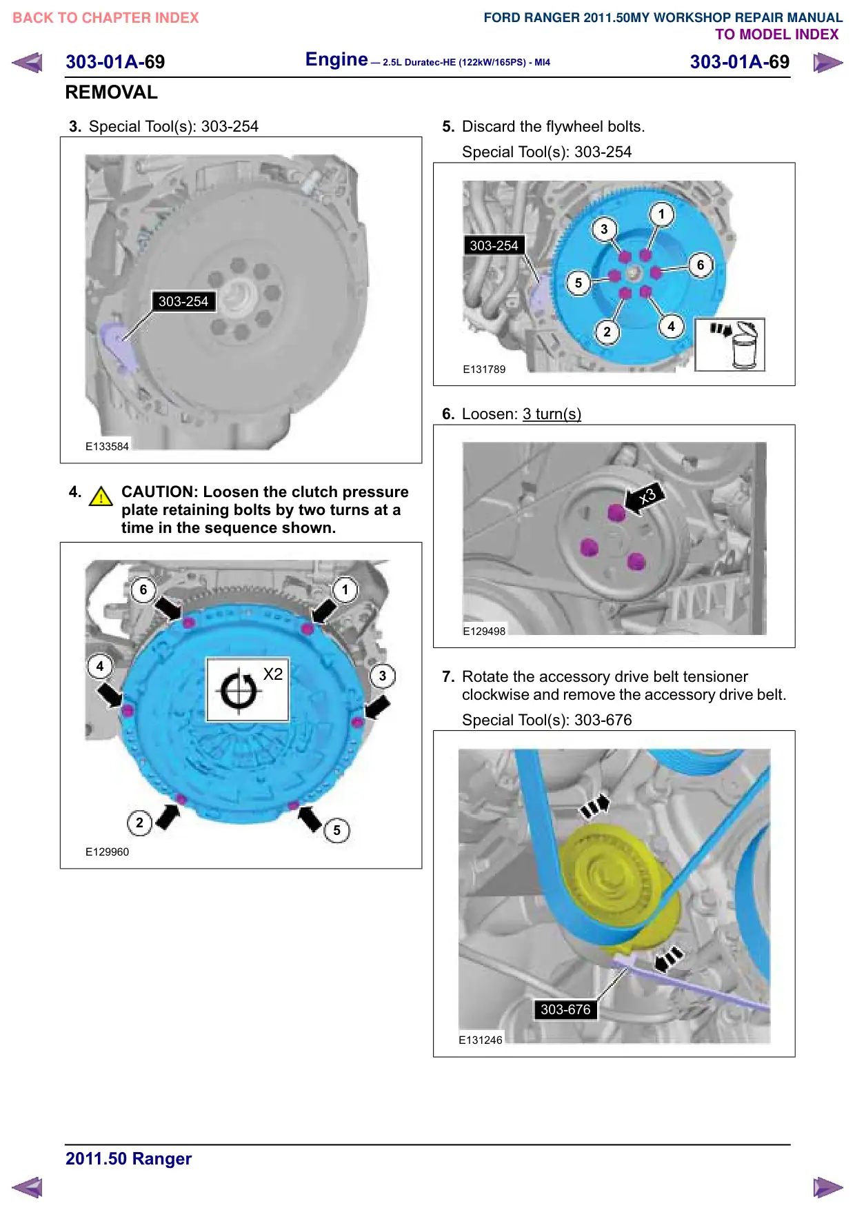
Engine – 2.5L Duratec-HE (122kW/165PS) - MI4
303-01A-70
303-01A-70
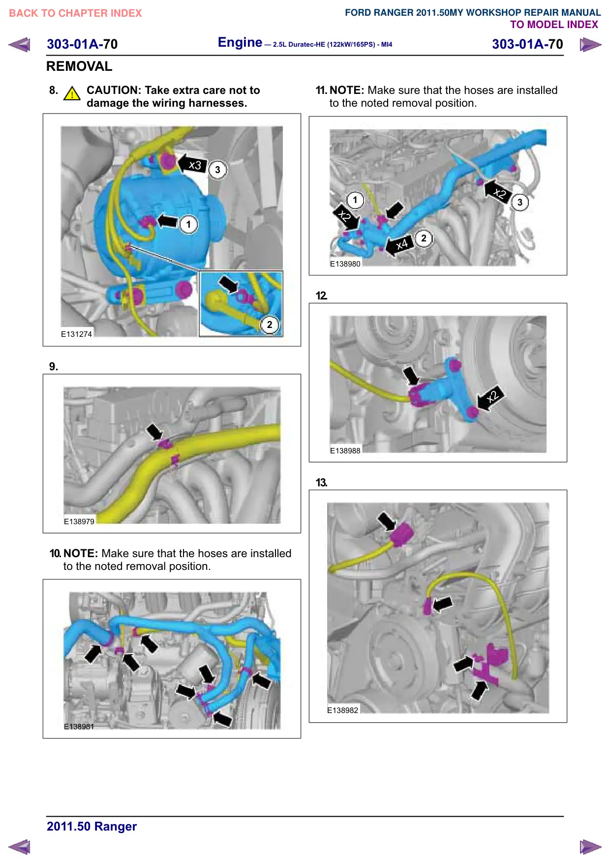
REMOVAL
8.
CAUTION: Take extra care not to
damage the wiring harnesses.
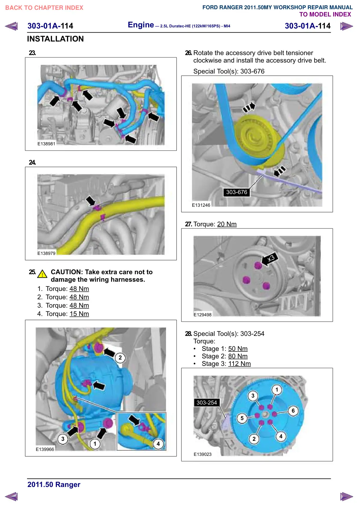
x3
3
1
2
E131274
9.
E138979
10.NOTE: Make sure that the hoses are installed
to the noted removal position.
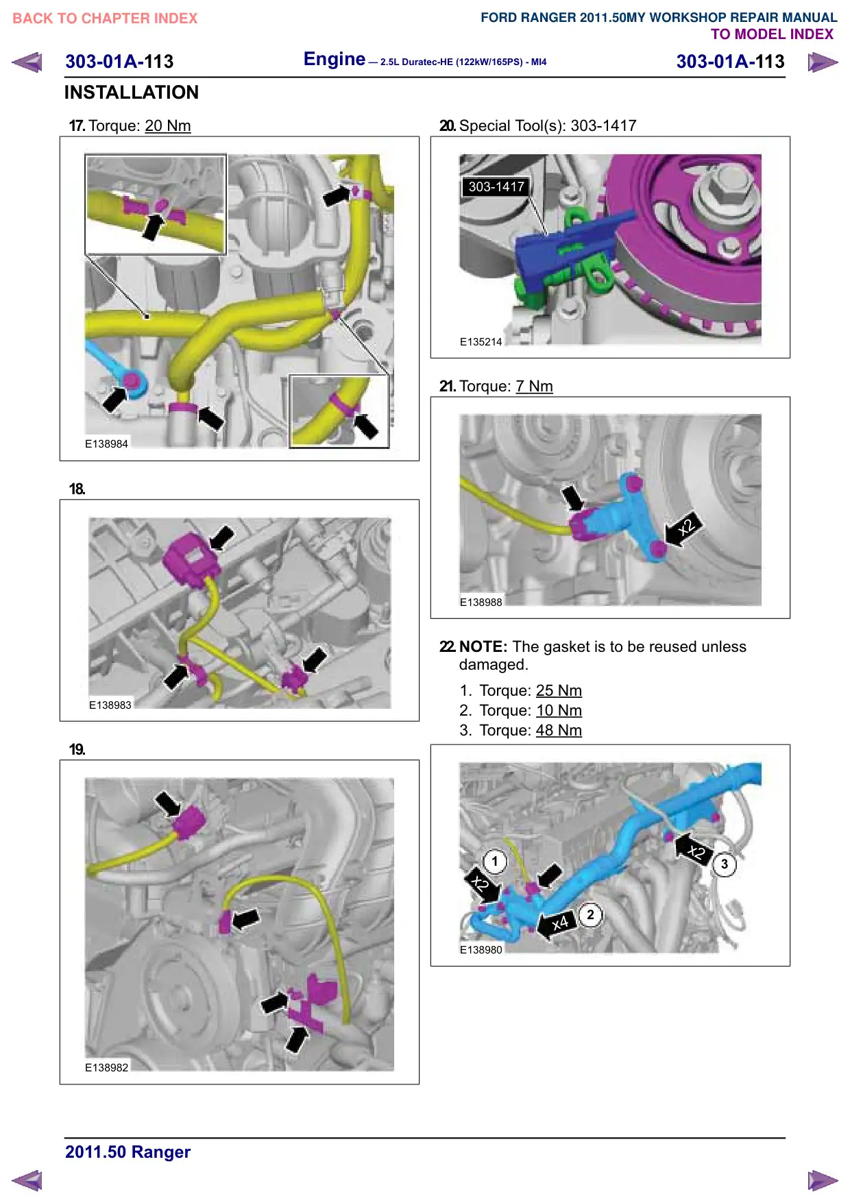
E138981
11. NOTE: Make sure that the hoses are installed
to the noted removal position.
x2
1
3
x2
2
x4
E138980
12.
x2
E138988
13.
E138982
Engine – 2.5L Duratec-HE (122kW/165PS) - MI4
303-01A-75
303-01A-75
DISASSEMBLY
Engine(21 134 8)
Disassembly
Special Tool(s) / General Equipment
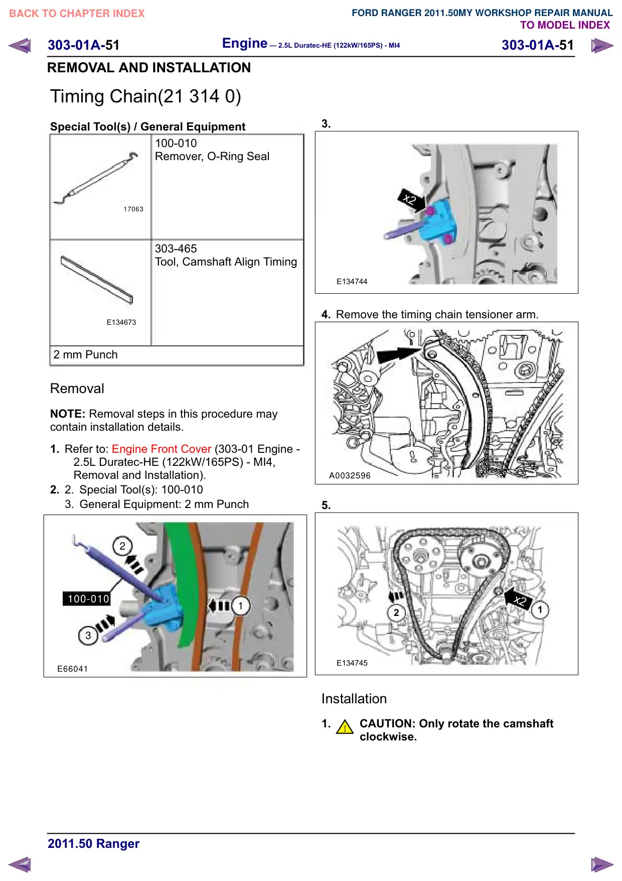
100-010
Remover, O-Ring Seal
17063
303-1416
Tool, Crank Damper Holding
E134674
303-409
Remover Crankshaft Seal
E134603
303-428
Separator, Oil Pan
21179
303-462
Installer, Connecting Rod
E139375
303-465
Tool, Camshaft Align Timing
E134673
Special Tool(s) / General Equipment
303-507
Timing Peg, Crankshaft TDC
PZ21210
2 mm Punch
1.
x11
x3
E131737
2.
CAUTION: Only rotate the crankshaft
clockwise.
Rotate the crankshaft until piston No. 1 is
approximately 45 degrees before top dead
center (TDC).
45°
E131991
303-01A-77
Engine – 2.5L Duratec-HE (122kW/165PS) - MI4
303-01A-77
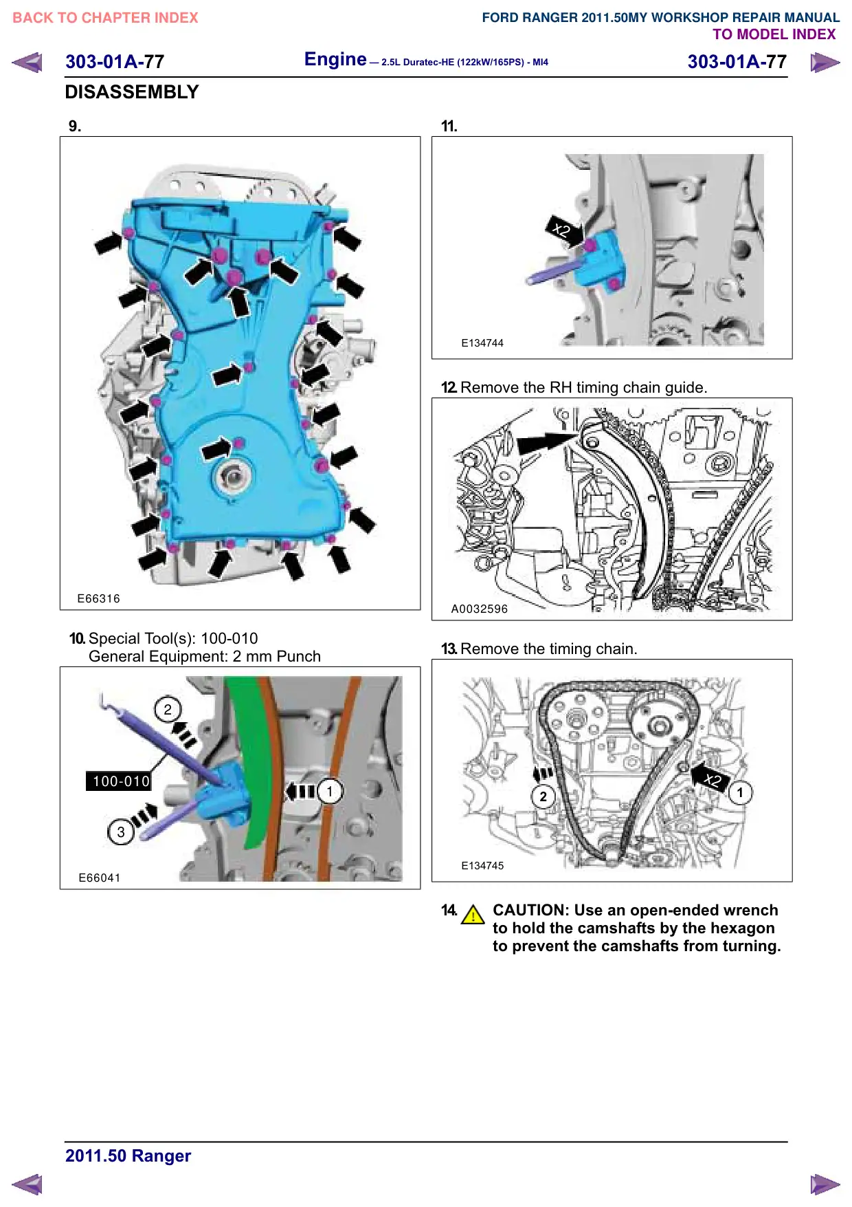
DISASSEMBLY
9.
E66316
10.Special Tool(s): 100-010
General Equipment: 2 mm Punch
2
100-010
1
3
E66041
11.
x2
E134744
12.Remove the RH timing chain guide.
A0032596
13.Remove the timing chain.
x2
1
2
E134745
14.
CAUTION: Use an open-ended wrench
to hold the camshafts by the hexagon
to prevent the camshafts from turning.
303-01A-78
Engine – 2.5L Duratec-HE (122kW/165PS) - MI4
303-01A-78
DISASSEMBLY
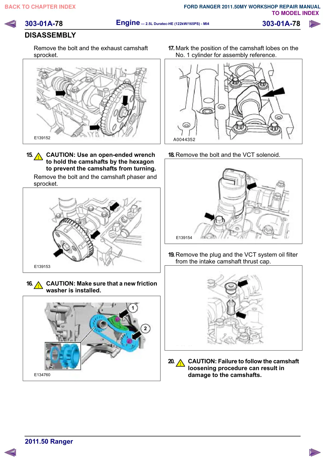
Remove the bolt and the exhaust camshaft
sprocket.
E139152
15.
CAUTION: Use an open-ended wrench
to hold the camshafts by the hexagon
to prevent the camshafts from turning.
Remove the bolt and the camshaft phaser and
sprocket.
E139153
16.
CAUTION: Make sure that a new friction
washer is installed.
1
2
E134760
17.Mark the position of the camshaft lobes on the
No. 1 cylinder for assembly reference.
A0044352
18.Remove the bolt and the VCT solenoid.
E139154
19.Remove the plug and the VCT system oil filter
from the intake camshaft thrust cap.
E139155
20.
CAUTION: Failure to follow the camshaft
loosening procedure can result in
damage to the camshafts.
Engine – 2.5L Duratec-HE (122kW/165PS) - MI4
303-01A-79
303-01A-79
DISASSEMBLY
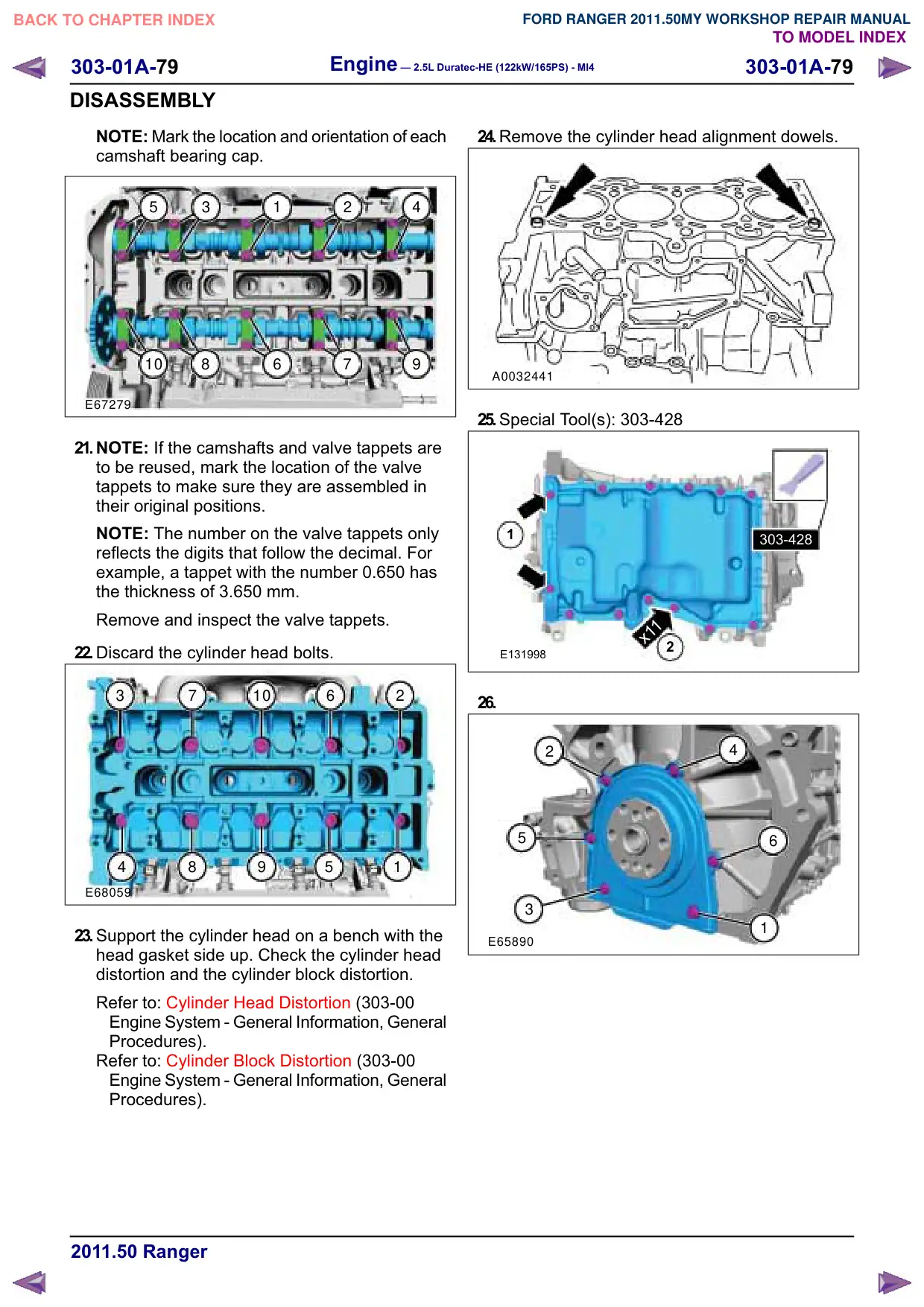
NOTE: Mark the location and orientation of each
camshaft bearing cap.
5
3
1
2
4
10
8
6
7
9
E67279
21.NOTE: If the camshafts and valve tappets are
to be reused, mark the location of the valve
tappets to make sure they are assembled in
their original positions.
NOTE: The number on the valve tappets only
reflects the digits that follow the decimal. For
example, a tappet with the number 0.650 has
the thickness of 3.650 mm.
Remove and inspect the valve tappets.
22.Discard the cylinder head bolts.
3
7
10
6
2
4
8
9
5
1
E68059
23.Support the cylinder head on a bench with the
head gasket side up. Check the cylinder head
distortion and the cylinder block distortion.
Refer to: Cylinder Head Distortion (303-00
Engine System - General Information, General
Procedures).
Refer to: Cylinder Block Distortion (303-00
Engine System - General Information, General
Procedures).
24.Remove the cylinder head alignment dowels.
A0032441
25.Special Tool(s): 303-428
1
303-428
x11
2
E131998
26.
2
4
5
6
3
1
E65890
303-01A-80
Engine – 2.5L Duratec-HE (122kW/165PS) - MI4
303-01A-80
DISASSEMBLY
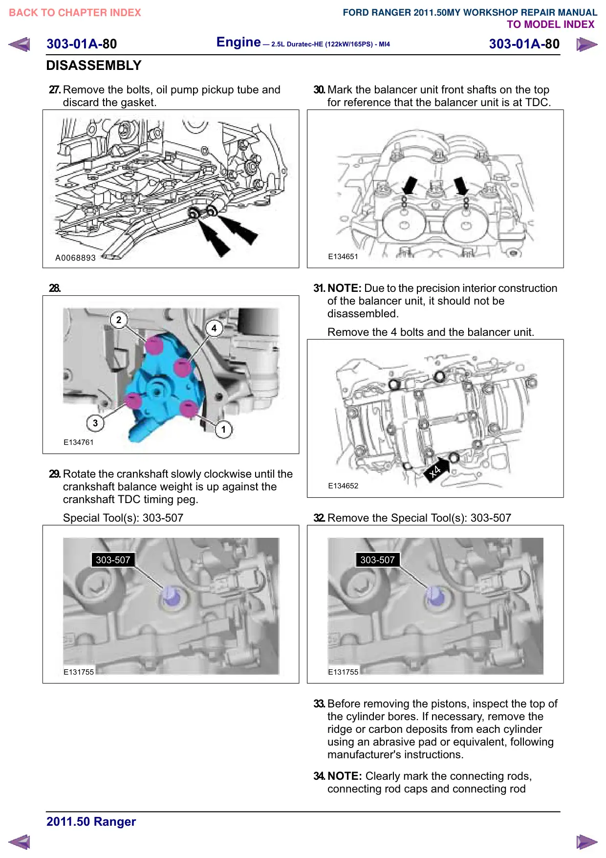
27.Remove the bolts, oil pump pickup tube and
discard the gasket.
A0068893
28.
2
4
3
1
E134761
29.Rotate the crankshaft slowly clockwise until the
crankshaft balance weight is up against the
crankshaft TDC timing peg.
Special Tool(s): 303-507
303-507
E131755
30.Mark the balancer unit front shafts on the top
for reference that the balancer unit is at TDC.
E134651
31.NOTE: Due to the precision interior construction
of the balancer unit, it should not be
disassembled.
Remove the 4 bolts and the balancer unit.
x4
E134652
32.Remove the Special Tool(s): 303-507
303-507
E131755
33.Before removing the pistons, inspect the top of
the cylinder bores. If necessary, remove the
ridge or carbon deposits from each cylinder
using an abrasive pad or equivalent, following
manufacturer's instructions.
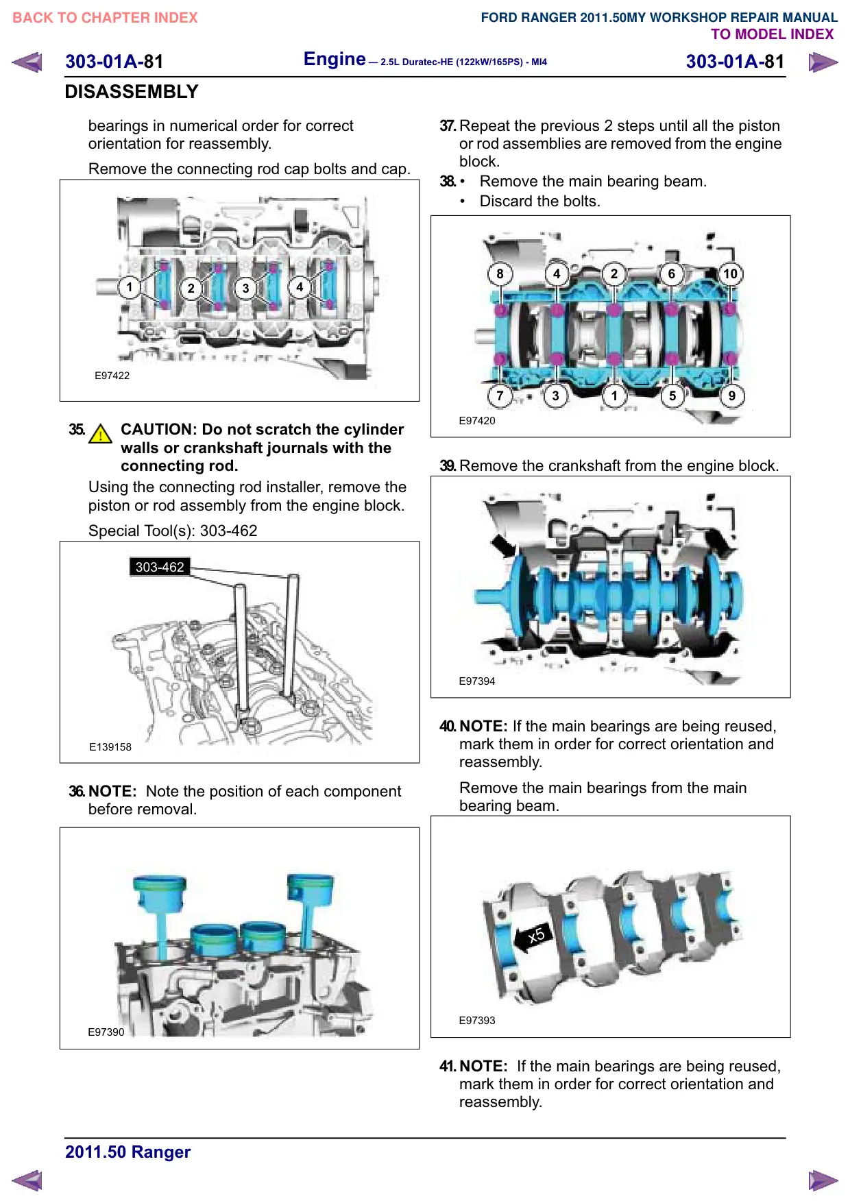
34.NOTE: Clearly mark the connecting rods,
connecting rod caps and connecting rod
303-01A-81
Engine – 2.5L Duratec-HE (122kW/165PS) - MI4
303-01A-81
DISASSEMBLY
bearings in numerical order for correct
orientation for reassembly.
Remove the connecting rod cap bolts and cap.
1
2
3
4
E97422
35.
CAUTION: Do not scratch the cylinder
walls or crankshaft journals with the
connecting rod.
Using the connecting rod installer, remove the
piston or rod assembly from the engine block.
Special Tool(s): 303-462
303-462
E139158
36.NOTE: Note the position of each component
before removal.
E97390
37.Repeat the previous 2 steps until all the piston
or rod assemblies are removed from the engine
block.
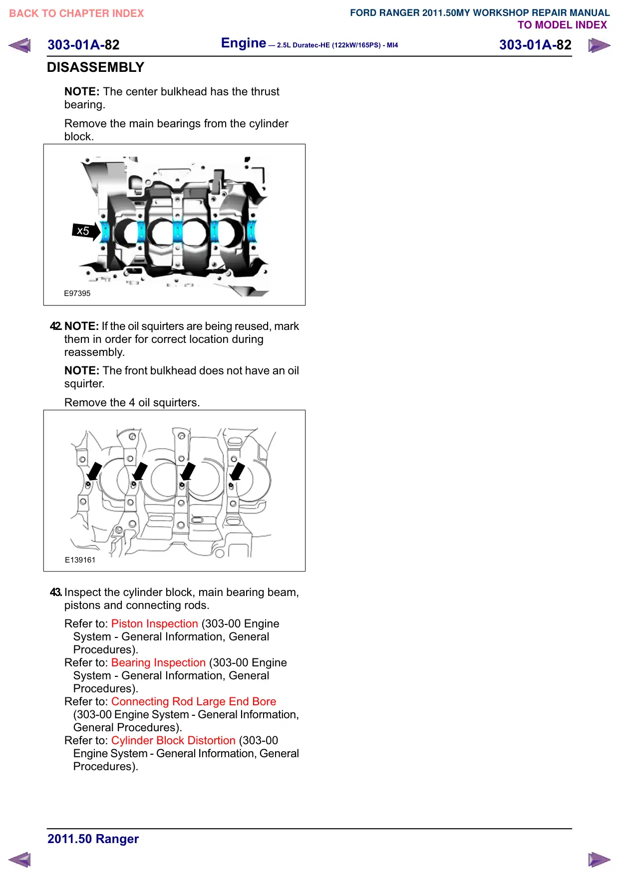
38.
Remove the main bearing beam.
Discard the bolts.
8
4
2
6
10
7
3
1
5
E97420
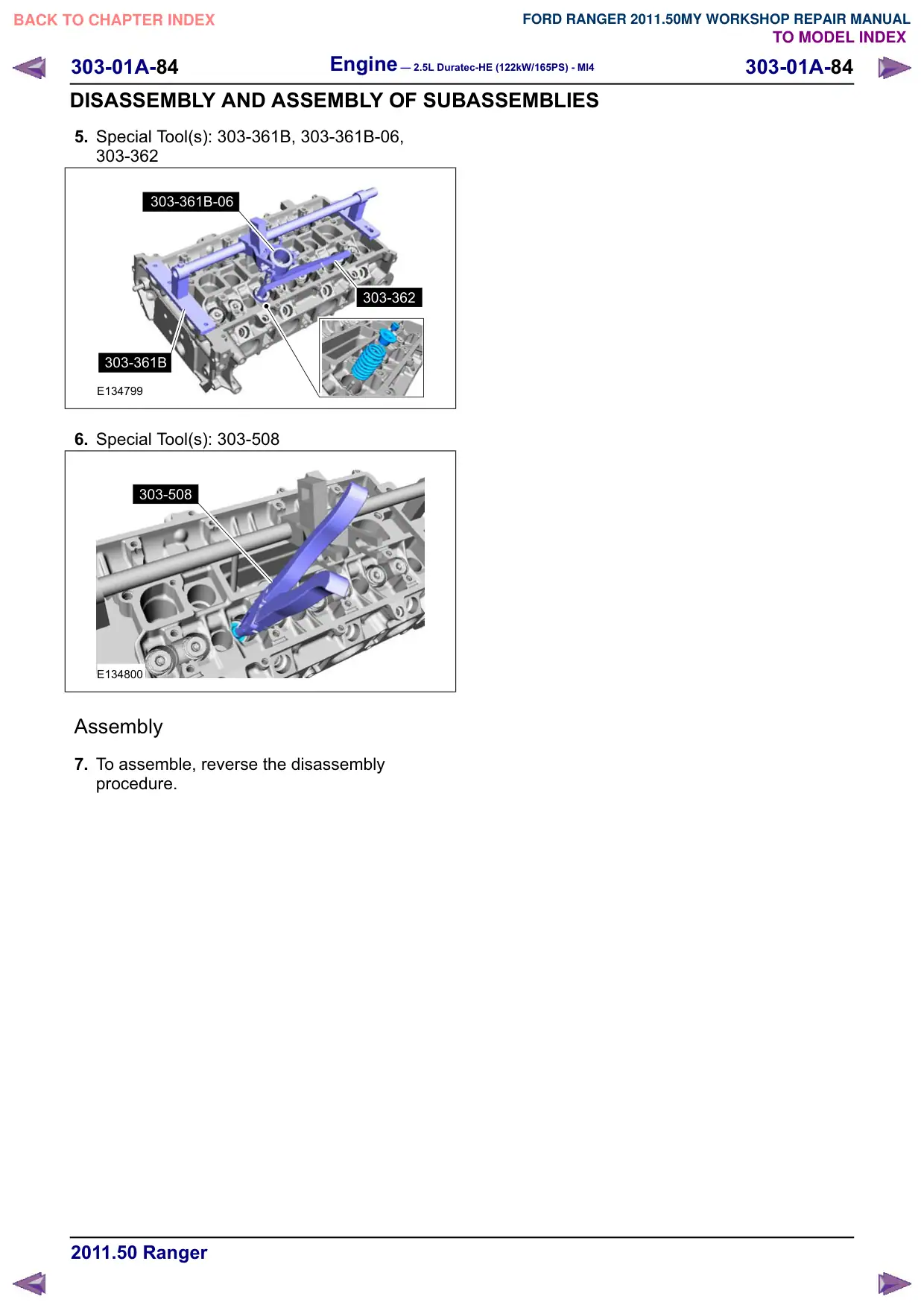
39.Remove the crankshaft from the engine block.
E97394
40.NOTE: If the main bearings are being reused,
mark them in order for correct orientation and
reassembly.
Remove the main bearings from the main
bearing beam.
x5
E97393
41.NOTE: If the main bearings are being reused,
mark them in order for correct orientation and
reassembly.
Engine – 2.5L Duratec-HE (122kW/165PS) - MI4
303-01A-82
303-01A-82
DISASSEMBLY
NOTE: The center bulkhead has the thrust
bearing.
Remove the main bearings from the cylinder
block.
x5
x5
E97395
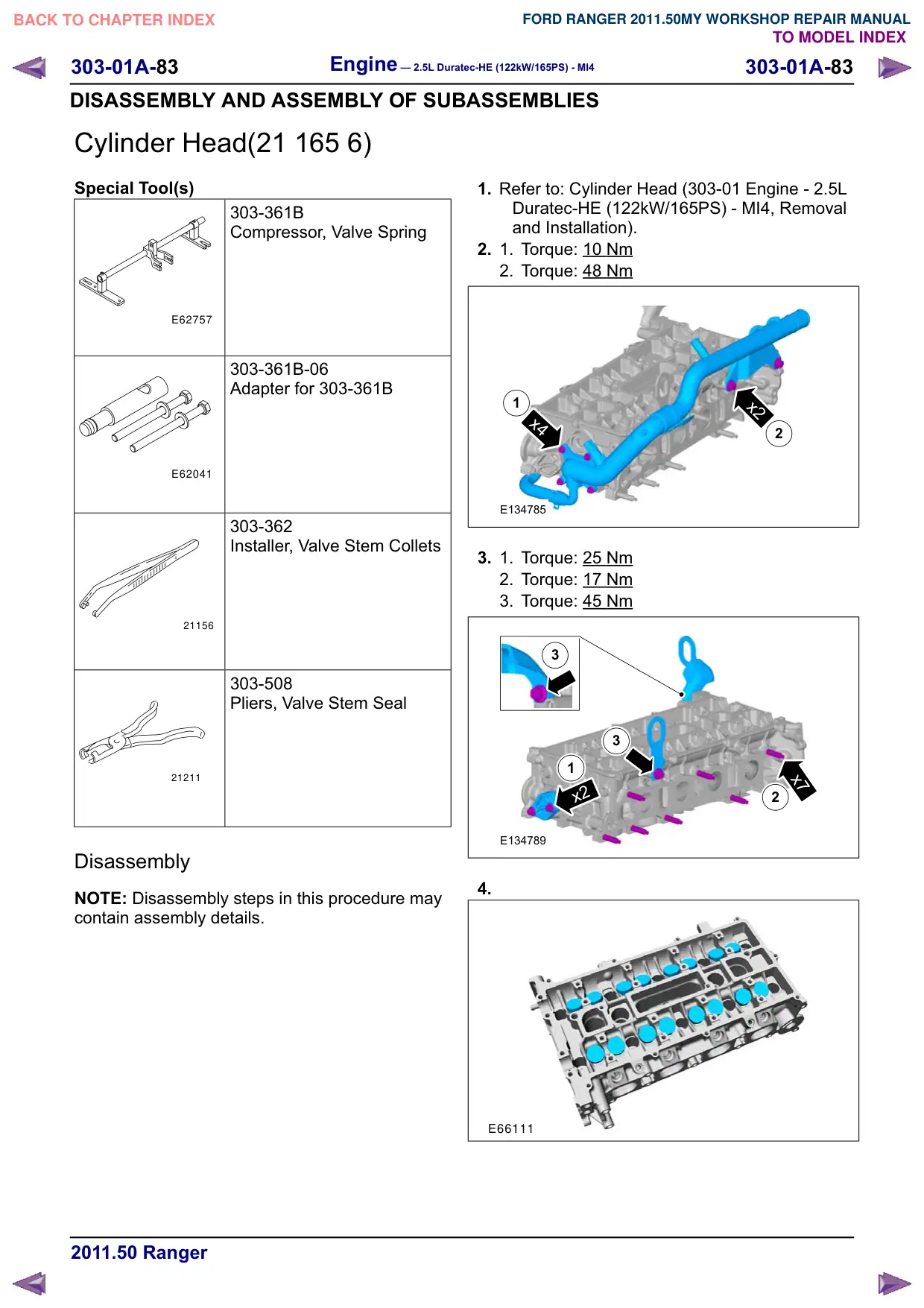
42.NOTE: If the oil squirters are being reused, mark
them in order for correct location during
reassembly.
NOTE: The front bulkhead does not have an oil
squirter.
Remove the 4 oil squirters.
E139161
43.Inspect the cylinder block, main bearing beam,
pistons and connecting rods.
Refer to: Piston Inspection (303-00 Engine
System - General Information, General
Procedures).
Refer to: Bearing Inspection (303-00 Engine
System - General Information, General
Procedures).
Refer to: Connecting Rod Large End Bore
(303-00 Engine System - General Information,
General Procedures).
Refer to: Cylinder Block Distortion (303-00
Engine System - General Information, General
Procedures).
Engine – 2.5L Duratec-HE (122kW/165PS) - MI4
303-01A-85
303-01A-85
ASSEMBLY
Engine(21 134 8)
Assembly
Special Tool(s)
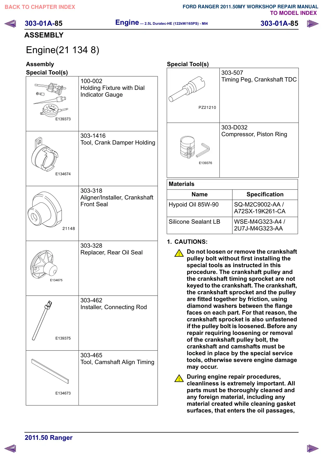
100-002
Holding Fixture with Dial
Indicator Gauge
E139373
303-1416
Tool, Crank Damper Holding
E134674
303-318
Aligner/Installer, Crankshaft
Front Seal
21148
303-328
Replacer, Rear Oil Seal
E134675
303-462
Installer, Connecting Rod
E139375
303-465
Tool, Camshaft Align Timing
E134673
Special Tool(s)
303-507
Timing Peg, Crankshaft TDC
PZ21210
303-D032
Compressor, Piston Ring
E139376
Materials
Name
Specification
Hypoid Oil 85W-90
SQ-M2C9002-AA /
A72SX-19K261-CA
Silicone Sealant LB
WSE-M4G323-A4 /
2U7J-M4G323-AA
1. CAUTIONS:
Do not loosen or remove the crankshaft
pulley bolt without first installing the
special tools as instructed in this
procedure. The crankshaft pulley and
the crankshaft timing sprocket are not
keyed to the crankshaft. The crankshaft,
the crankshaft sprocket and the pulley
are fitted together by friction, using
diamond washers between the flange
faces on each part. For that reason, the
crankshaft sprocket is also unfastened
if the pulley bolt is loosened. Before any
repair requiring loosening or removal
of the crankshaft pulley bolt, the
crankshaft and camshafts must be
locked in place by the special service
tools, otherwise severe engine damage
may occur.
During engine repair procedures,
cleanliness is extremely important. All
parts must be thoroughly cleaned and
any foreign material, including any
material created while cleaning gasket
surfaces, that enters the oil passages,
303-01A-86
Engine – 2.5L Duratec-HE (122kW/165PS) - MI4
303-01A-86
ASSEMBLY
coolant passages or the oil pan, can
cause engine failure.
NOTE: Assembly of the engine requires various
inspections/measurements of the engine
components (engine block, crankshaft,
connecting rods, pistons and piston rings).
These inspections/measurements will aid in
determining if the engine components will
require replacement.
2. NOTE: If the oil squirters are being reused, they
must be installed in the same location as
marked during disassembly.
NOTE: The front bulkhead does not have an
oil squirter.
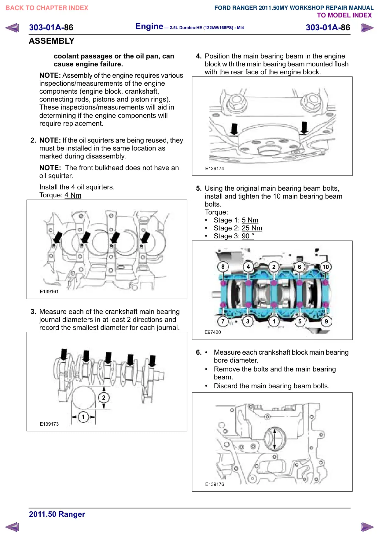
Install the 4 oil squirters.
Torque: 4
Nm
E139161
3. Measure each of the crankshaft main bearing
journal diameters in at least 2 directions and
record the smallest diameter for each journal.
2
1
E139173
4. Position the main bearing beam in the engine
block with the main bearing beam mounted flush
with the rear face of the engine block.
E139174
5. Using the original main bearing beam bolts,
install and tighten the 10 main bearing beam
bolts.
Torque:
Stage 1: 5
Nm
Stage 2: 25 Nm
Stage 3: 90 °
8
4
2
6
10
7
3
1
5
E97420
6.
Measure each crankshaft block main bearing
bore diameter.
Remove the bolts and the main bearing
beam.
Discard the main bearing beam bolts.
E139176
Engine – 2.5L Duratec-HE (122kW/165PS) - MI4
303-01A-87
303-01A-87
ASSEMBLY
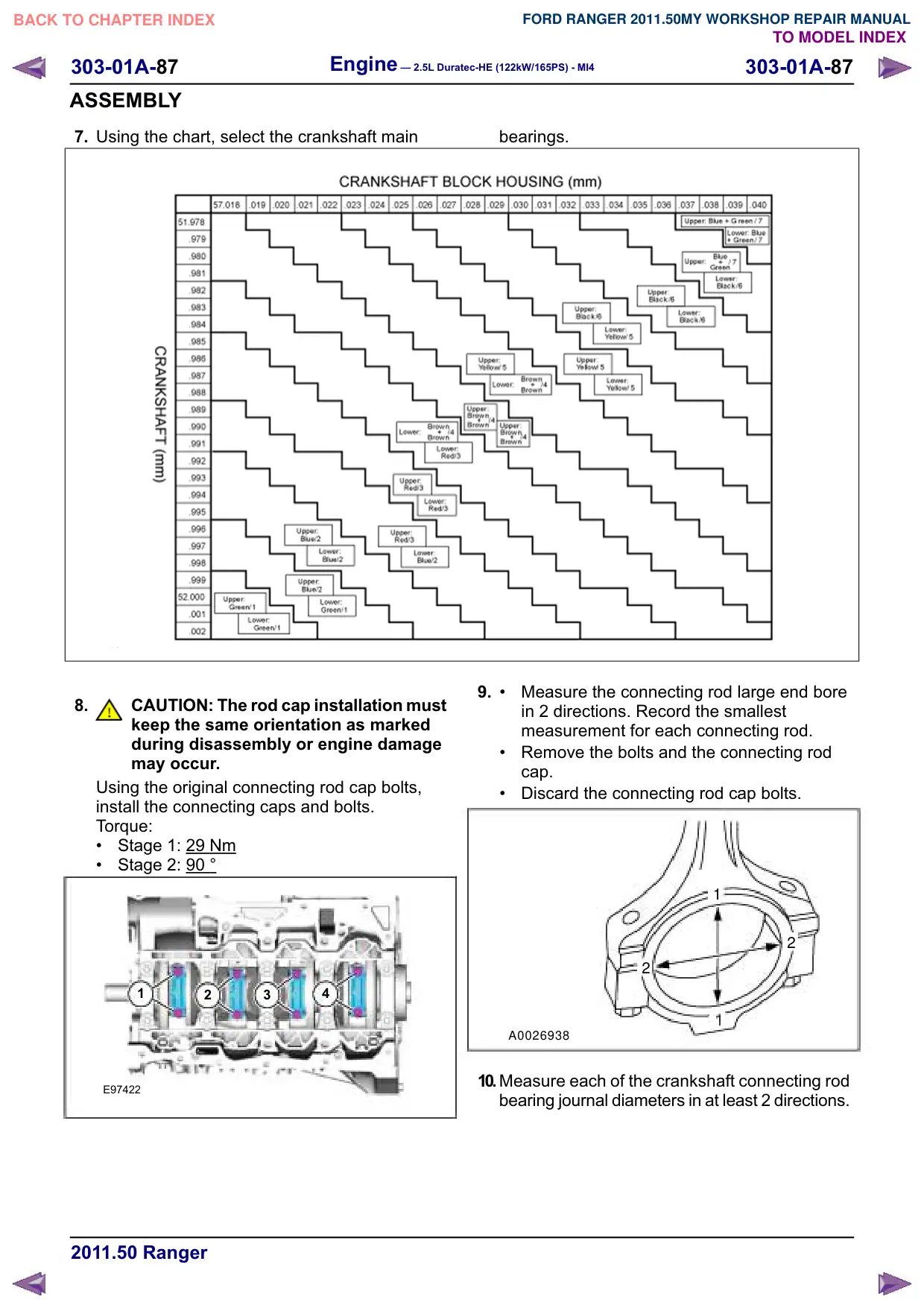
7. Using the chart, select the crankshaft main
E139177
8.
CAUTION: The rod cap installation must
keep the same orientation as marked
during disassembly or engine damage
may occur.
Using the original connecting rod cap bolts,
install the connecting caps and bolts.
Torque:
Stage 1: 29
Nm
Stage 2: 90
1
2
3
4
E97422
bearings.
9.
Measure the connecting rod large end bore
in 2 directions. Record the smallest
measurement for each connecting rod.
Remove the bolts and the connecting rod
cap.
Discard the connecting rod cap bolts.
1
2
2
A0026938
10.Measure each of the crankshaft connecting rod
bearing journal diameters in at least 2 directions.
303-01A-88
Engine – 2.5L Duratec-HE (122kW/165PS) - MI4
303-01A-88
ASSEMBLY
Record the smallest measurement for each
connecting rod journal.
2
1
E139178
E139179
12.NOTE: Before assembling the cylinder block,
all sealing surfaces must be free of chips, dirt,
paint and foreign material. Also, make sure the
coolant and oil passages are clear.
NOTE: If reusing the crankshaft main bearings,
install them in their original positions and
orientation as noted during disassembly.
NOTE: The center bulkhead is the thrust
bearing.
NOTE: Make sure that these components are
installed to the noted removal position.
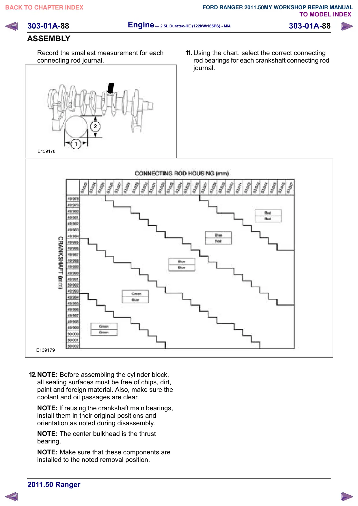
11. Using the chart, select the correct connecting
rod bearings for each crankshaft connecting rod
journal.
Engine – 2.5L Duratec-HE (122kW/165PS) - MI4
303-01A-89
303-01A-89
ASSEMBLY
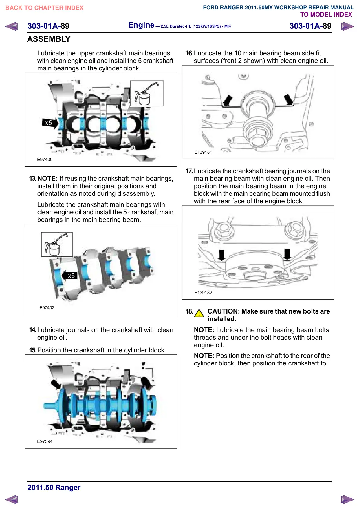
Lubricate the upper crankshaft main bearings
with clean engine oil and install the 5 crankshaft
main bearings in the cylinder block.
x5
E97400
13.NOTE: If reusing the crankshaft main bearings,
install them in their original positions and
orientation as noted during disassembly.
Lubricate the crankshaft main bearings with
clean engine oil and install the 5 crankshaft main
bearings in the main bearing beam.
x5
E97402
14.Lubricate journals on the crankshaft with clean
engine oil.
15.Position the crankshaft in the cylinder block.
E97394
16.Lubricate the 10 main bearing beam side fit
surfaces (front 2 shown) with clean engine oil.
E139181
17.Lubricate the crankshaft bearing journals on the
main bearing beam with clean engine oil. Then
position the main bearing beam in the engine
block with the main bearing beam mounted flush
with the rear face of the engine block.
E139182
18.
CAUTION: Make sure that new bolts are
installed.
NOTE: Lubricate the main bearing beam bolts
threads and under the bolt heads with clean
engine oil.
NOTE: Position the crankshaft to the rear of the
cylinder block, then position the crankshaft to
Engine – 2.5L Duratec-HE (122kW/165PS) - MI4
303-01A-90
303-01A-90
ASSEMBLY
the front of the cylinder block before tightening
the main bearing beam bolts.
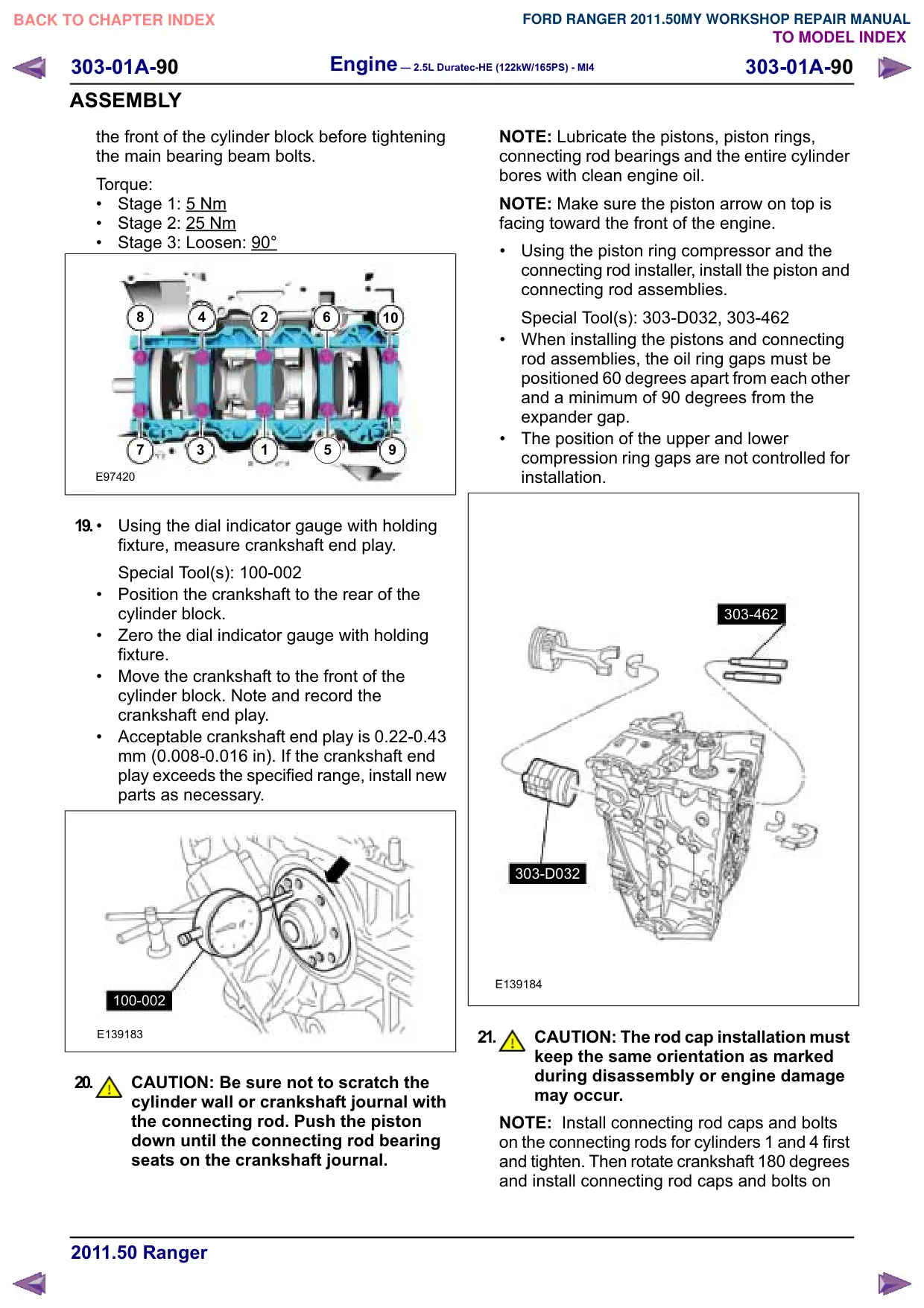
Torque:
Stage 1: 5
Nm
Stage 2: 25
Nm
Stage 3: Loosen: 90°
8
4
2
6
10
7
3
1
5
E97420
19.
Using the dial indicator gauge with holding
fixture, measure crankshaft end play.
Special Tool(s): 100-002
Position the crankshaft to the rear of the
cylinder block.
Zero the dial indicator gauge with holding
fixture.
Move the crankshaft to the front of the
cylinder block. Note and record the
crankshaft end play.
Acceptable crankshaft end play is 0.22-0.43
mm (0.008-0.016 in). If the crankshaft end
play exceeds the specified range, install new
parts as necessary.
100-002
E139183
20.
CAUTION: Be sure not to scratch the
cylinder wall or crankshaft journal with
the connecting rod. Push the piston
down until the connecting rod bearing
seats on the crankshaft journal.
NOTE: Lubricate the pistons, piston rings,
connecting rod bearings and the entire cylinder
bores with clean engine oil.
NOTE: Make sure the piston arrow on top is
facing toward the front of the engine.
Using the piston ring compressor and the
connecting rod installer, install the piston and
connecting rod assemblies.
Special Tool(s): 303-D032, 303-462
When installing the pistons and connecting
rod assemblies, the oil ring gaps must be
positioned 60 degrees apart from each other
and a minimum of 90 degrees from the
expander gap.
The position of the upper and lower
compression ring gaps are not controlled for
installation.
303-462
303-D032
E139184
21.
CAUTION: The rod cap installation must
keep the same orientation as marked
during disassembly or engine damage
may occur.
NOTE: Install connecting rod caps and bolts
on the connecting rods for cylinders 1 and 4 first
and tighten. Then rotate crankshaft 180 degrees
and install connecting rod caps and bolts on
Engine – 2.5L Duratec-HE (122kW/165PS) - MI4
303-01A-91
303-01A-91
ASSEMBLY
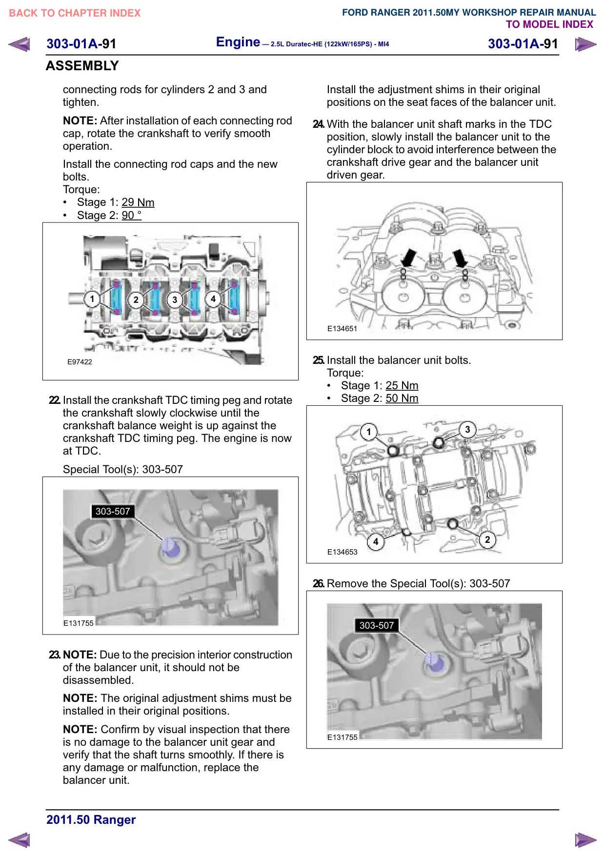
connecting rods for cylinders 2 and 3 and
tighten.
NOTE: After installation of each connecting rod
cap, rotate the crankshaft to verify smooth
operation.
Install the connecting rod caps and the new
bolts.
Torque:
Stage 1: 29
Nm
Stage 2: 90 °
1
2
3
4
E97422
22.Install the crankshaft TDC timing peg and rotate
the crankshaft slowly clockwise until the
crankshaft balance weight is up against the
crankshaft TDC timing peg. The engine is now
at TDC.
Special Tool(s): 303-507
303-507
E131755
23.NOTE: Due to the precision interior construction
of the balancer unit, it should not be
disassembled.
NOTE: The original adjustment shims must be
installed in their original positions.
NOTE: Confirm by visual inspection that there
is no damage to the balancer unit gear and
verify that the shaft turns smoothly. If there is
any damage or malfunction, replace the
balancer unit.
Install the adjustment shims in their original
positions on the seat faces of the balancer unit.
24.With the balancer unit shaft marks in the TDC
position, slowly install the balancer unit to the
cylinder block to avoid interference between the
crankshaft drive gear and the balancer unit
driven gear.
E134651
25.Install the balancer unit bolts.
Torque:
Stage 1: 25
Nm
Stage 2: 50 Nm
1
3
4
2
E134653
26.Remove the Special Tool(s): 303-507
303-507
E131755
303-01A-92
Engine – 2.5L Duratec-HE (122kW/165PS) - MI4
303-01A-92
ASSEMBLY
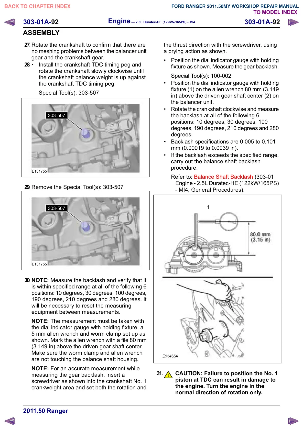
27.Rotate the crankshaft to confirm that there are
no meshing problems between the balancer unit
gear and the crankshaft gear.
28.
Install the crankshaft TDC timing peg and
rotate the crankshaft slowly clockwise until
the crankshaft balance weight is up against
the crankshaft TDC timing peg.
Special Tool(s): 303-507
303-507
E131755
29.Remove the Special Tool(s): 303-507
303-507
E131755
30.NOTE: Measure the backlash and verify that it
is within specified range at all of the following 6
positions: 10 degrees, 30 degrees, 100 degrees,
190 degrees, 210 degrees and 280 degrees. It
will be necessary to reset the measuring
equipment between measurements.
NOTE: The measurement must be taken with
the dial indicator gauge with holding fixture, a
5 mm allen wrench and worm clamp set up as
shown. Mark the allen wrench with a file 80 mm
(3.149 in) above the driven gear shaft center.
Make sure the worm clamp and allen wrench
are not touching the balance shaft housing.
NOTE: For an accurate measurement while
measuring the gear backlash, insert a
screwdriver as shown into the crankshaft No. 1
crankweight area and set both the rotation and
the thrust direction with the screwdriver, using
a prying action as shown.
Position the dial indicator gauge with holding
fixture as shown. Measure the gear backlash.
Special Tool(s): 100-002
Position the dial indicator gauge with holding
fixture (1) on the allen wrench 80 mm (3.149
in) above the driven gear shaft center (2) on
the balancer unit.
Rotate the crankshaft clockwise and measure
the backlash at all of the following 6
positions: 10 degrees, 30 degrees, 100
degrees, 190 degrees, 210 degrees and 280
degrees.
Backlash specifications are 0.005 to 0.101
mm (0.00019 to 0.0039 in).
If the backlash exceeds the specified range,
carry out the balance shaft backlash
procedure.
Refer to: Balance Shaft Backlash (303-01
Engine - 2.5L Duratec-HE (122kW/165PS)
- MI4, General Procedures).
1
E134654
31.
CAUTION: Failure to position the No. 1
piston at TDC can result in damage to
the engine. Turn the engine in the
normal direction of rotation only.
Engine – 2.5L Duratec-HE (122kW/165PS) - MI4
303-01A-93
303-01A-93
ASSEMBLY
Turn the crankshaft clockwise to position the
No. 1 piston at TDC.
32.NOTE: The crankshaft TDC timing peg will
contact the crankshaft and prevent it from
turning past TDC. However, the crankshaft can
still be rotated in the counterclockwise direction.
The crankshaft must remain at the TDC position
until the timing drive components and crankshaft
pulley are installed. Install the crankshaft TDC
timing peg.
Install the crankshaft TDC timing peg.
Special Tool(s): 303-507
303-507
E131755
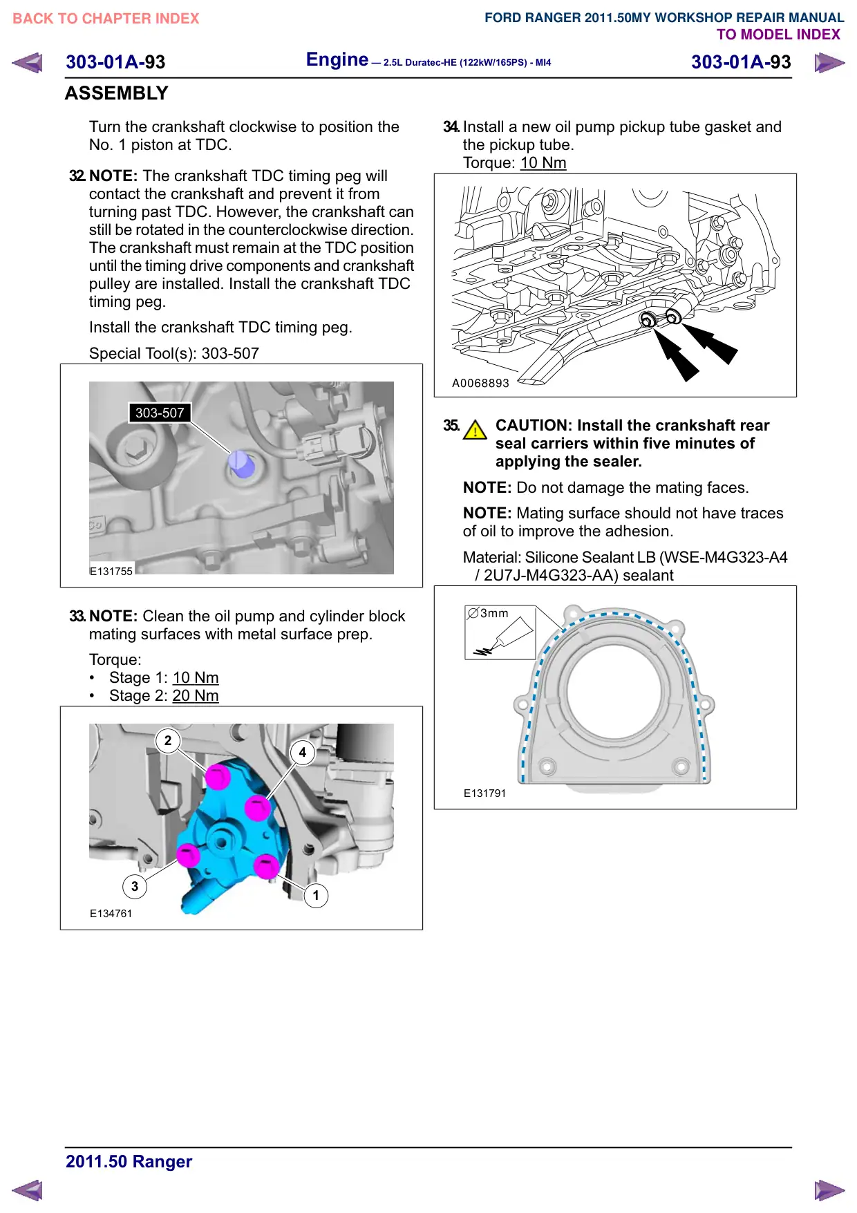
33.NOTE: Clean the oil pump and cylinder block
mating surfaces with metal surface prep.
Torque:
Stage 1: 10 Nm
Stage 2: 20 Nm
2
4
3
1
E134761
34.Install a new oil pump pickup tube gasket and
the pickup tube.
Torque: 10 Nm
A0068893
35.
CAUTION: Install the crankshaft rear
seal carriers within five minutes of
applying the sealer.
NOTE: Do not damage the mating faces.
NOTE: Mating surface should not have traces
of oil to improve the adhesion.
Material: Silicone Sealant LB (WSE-M4G323-A4
/ 2U7J-M4G323-AA) sealant
3mm
E131791
303-01A-94
Engine – 2.5L Duratec-HE (122kW/165PS) - MI4
303-01A-94
ASSEMBLY
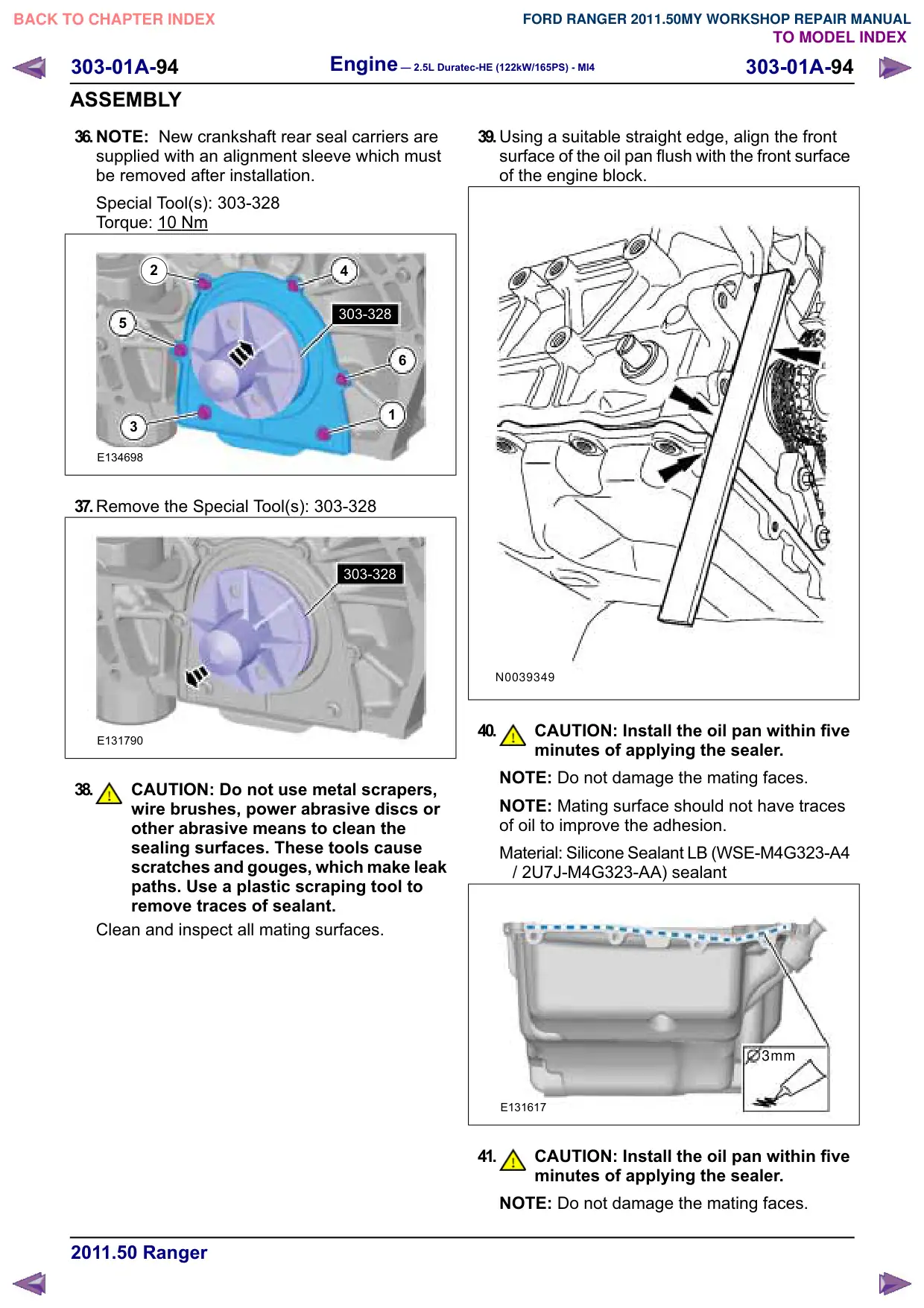
36.NOTE: New crankshaft rear seal carriers are
supplied with an alignment sleeve which must
be removed after installation.
Special Tool(s): 303-328
Torque: 10
Nm
2
4
303-328
5
6
1
3
E134698
37.Remove the Special Tool(s): 303-328
303-328
E131790
38.
CAUTION: Do not use metal scrapers,
wire brushes, power abrasive discs or
other abrasive means to clean the
sealing surfaces. These tools cause
scratches and gouges, which make leak
paths. Use a plastic scraping tool to
remove traces of sealant.
Clean and inspect all mating surfaces.
39.Using a suitable straight edge, align the front
surface of the oil pan flush with the front surface
of the engine block.
N0039349
40.
CAUTION: Install the oil pan within five
minutes of applying the sealer.
NOTE: Do not damage the mating faces.
NOTE: Mating surface should not have traces
of oil to improve the adhesion.
Material: Silicone Sealant LB (WSE-M4G323-A4
/ 2U7J-M4G323-AA) sealant
3mm
E131617
41.
CAUTION: Install the oil pan within five
minutes of applying the sealer.
NOTE: Do not damage the mating faces.
Engine – 2.5L Duratec-HE (122kW/165PS) - MI4
303-01A-95
303-01A-95
ASSEMBLY
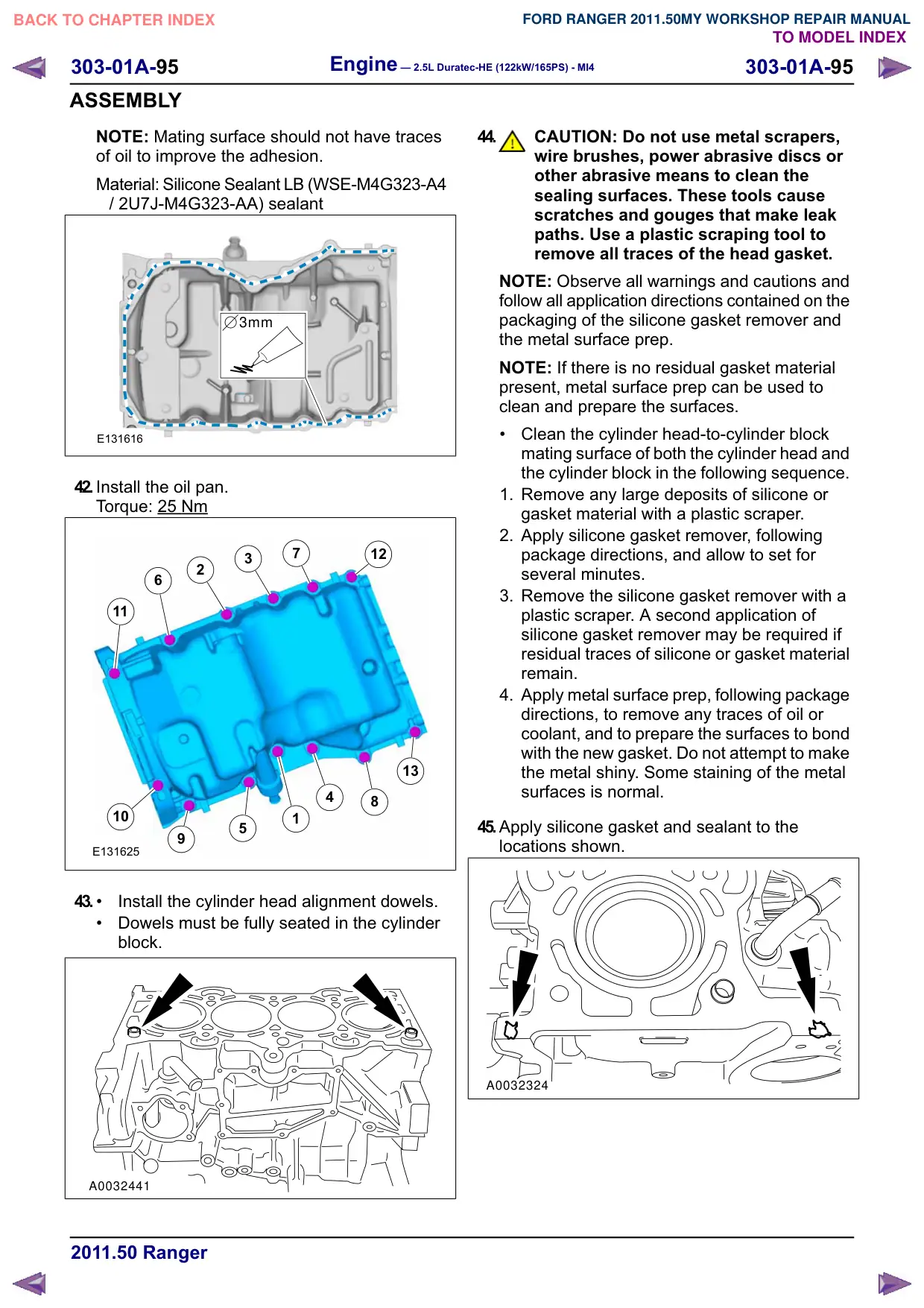
NOTE: Mating surface should not have traces
of oil to improve the adhesion.
Material: Silicone Sealant LB (WSE-M4G323-A4
/ 2U7J-M4G323-AA) sealant
3mm
E131616
42.Install the oil pan.
Torque: 25 Nm
7
12
3
2
6
11
13
4
8
10
1
5
E131625
43.
Install the cylinder head alignment dowels.
Dowels must be fully seated in the cylinder
block.
A0032441
44.
CAUTION: Do not use metal scrapers,
wire brushes, power abrasive discs or
other abrasive means to clean the
sealing surfaces. These tools cause
scratches and gouges that make leak
paths. Use a plastic scraping tool to
remove all traces of the head gasket.
NOTE: Observe all warnings and cautions and
follow all application directions contained on the
packaging of the silicone gasket remover and
the metal surface prep.
NOTE: If there is no residual gasket material
present, metal surface prep can be used to
clean and prepare the surfaces.
Clean the cylinder head-to-cylinder block
mating surface of both the cylinder head and
the cylinder block in the following sequence.
1. Remove any large deposits of silicone or
gasket material with a plastic scraper.
2. Apply silicone gasket remover, following
package directions, and allow to set for
several minutes.
3. Remove the silicone gasket remover with a
plastic scraper. A second application of
silicone gasket remover may be required if
residual traces of silicone or gasket material
remain.
4. Apply metal surface prep, following package
directions, to remove any traces of oil or
coolant, and to prepare the surfaces to bond
with the new gasket. Do not attempt to make
the metal shiny. Some staining of the metal
surfaces is normal.
45.Apply silicone gasket and sealant to the
locations shown.
A0032324
303-01A-96
Engine – 2.5L Duratec-HE (122kW/165PS) - MI4
303-01A-96
ASSEMBLY
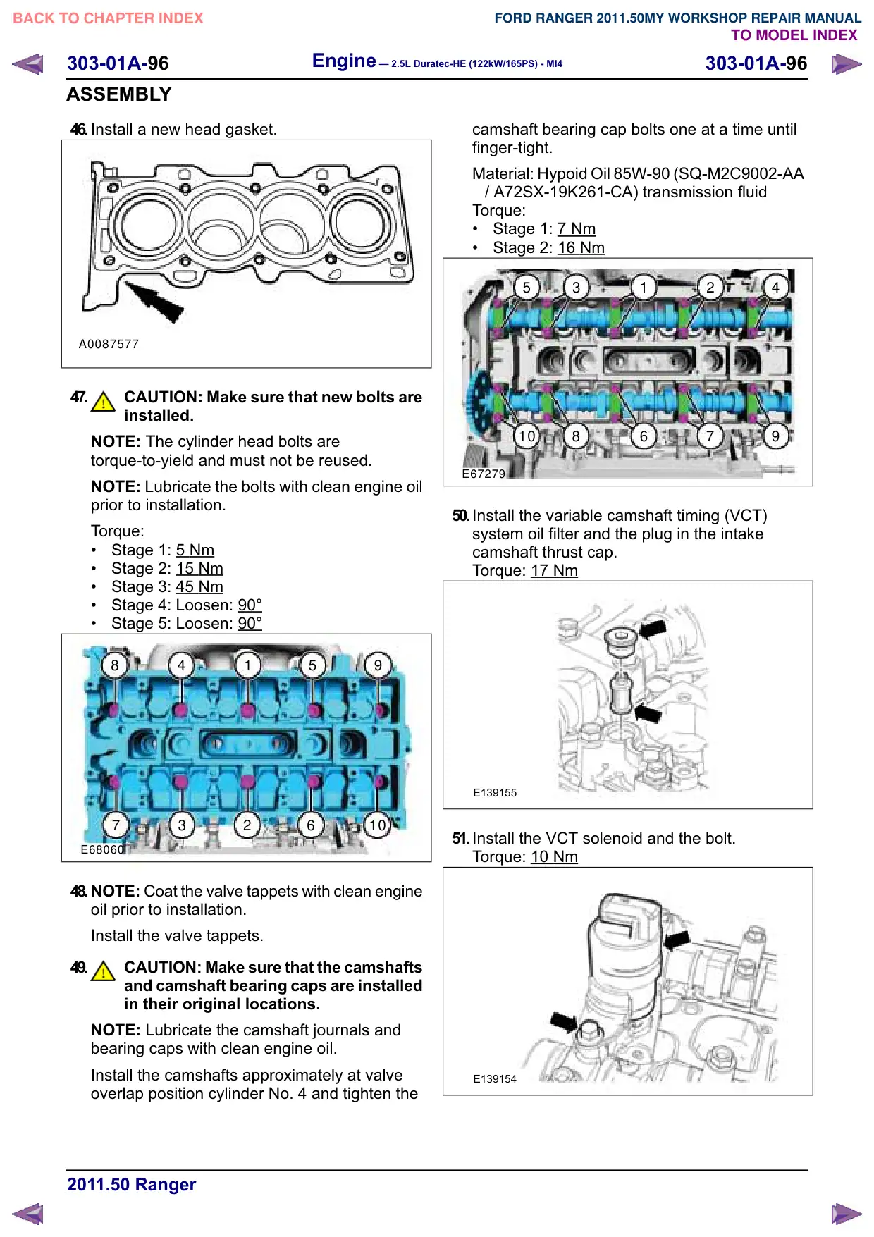
46.Install a new head gasket.
A0087577
47.
CAUTION: Make sure that new bolts are
installed.
NOTE: The cylinder head bolts are
torque-to-yield and must not be reused.
NOTE: Lubricate the bolts with clean engine oil
prior to installation.
Torque:
Stage 1: 5 Nm
Stage 2: 15 Nm
Stage 3: 45 Nm
Stage 4: Loosen: 90°
Stage 5: Loosen: 90°
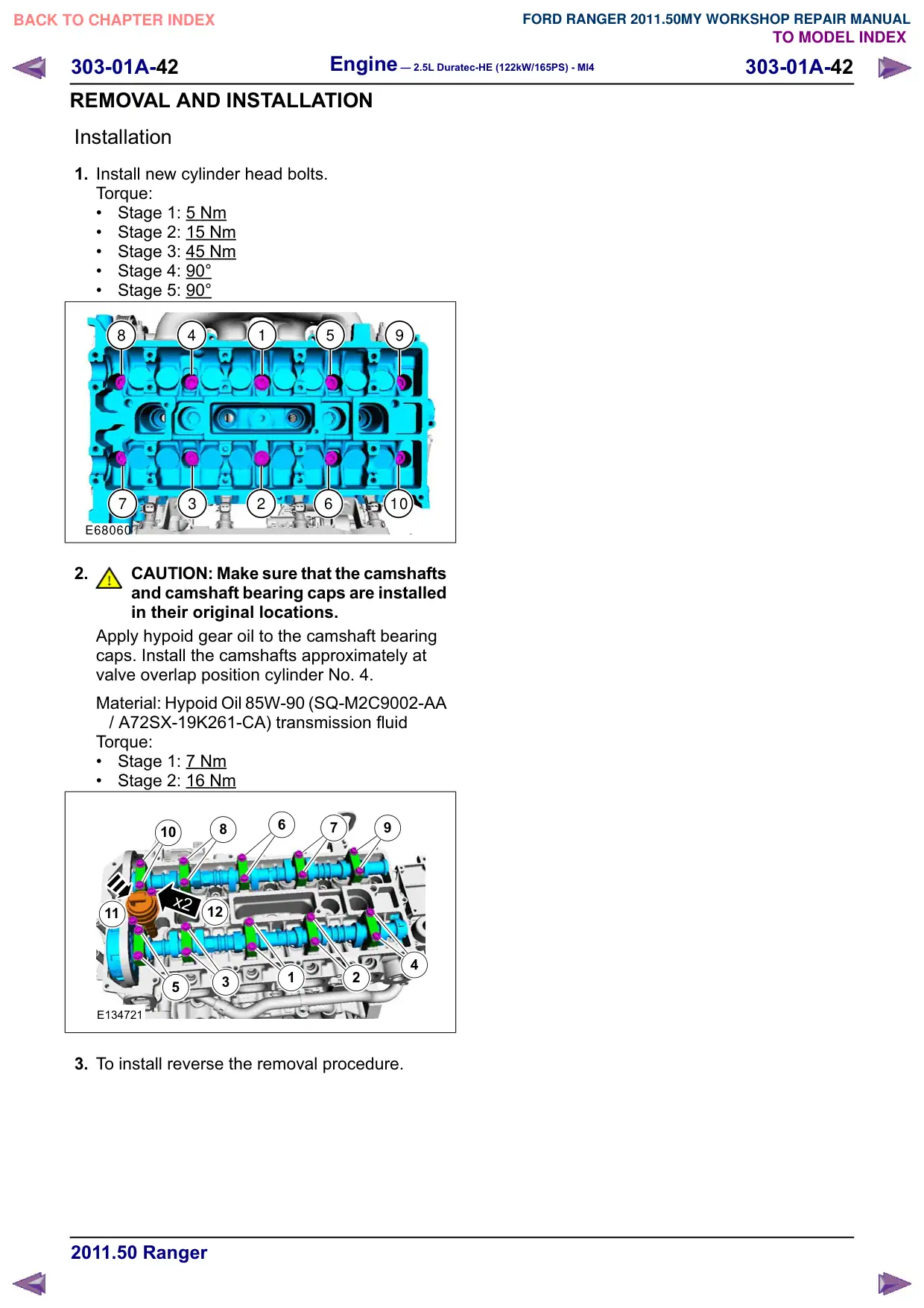
8
4
1
5
9
7
3
2
6
10
E68060
48.NOTE: Coat the valve tappets with clean engine
oil prior to installation.
Install the valve tappets.
49.
CAUTION: Make sure that the camshafts
and camshaft bearing caps are installed
in their original locations.
NOTE: Lubricate the camshaft journals and
bearing caps with clean engine oil.
Install the camshafts approximately at valve
overlap position cylinder No. 4 and tighten the
camshaft bearing cap bolts one at a time until
finger-tight.
Material: Hypoid Oil 85W-90 (SQ-M2C9002-AA
/ A72SX-19K261-CA) transmission fluid
Torque:
Stage 1: 7
Nm
Stage 2: 16 Nm
5
3
1
2
4
10
8
6
7
9
E67279
50.Install the variable camshaft timing (VCT)
system oil filter and the plug in the intake
camshaft thrust cap.
Torque: 17
Nm
E139155
51.Install the VCT solenoid and the bolt.
Torque: 10
Nm
E139154
303-01A-97
Engine – 2.5L Duratec-HE (122kW/165PS) - MI4
303-01A-97
ASSEMBLY
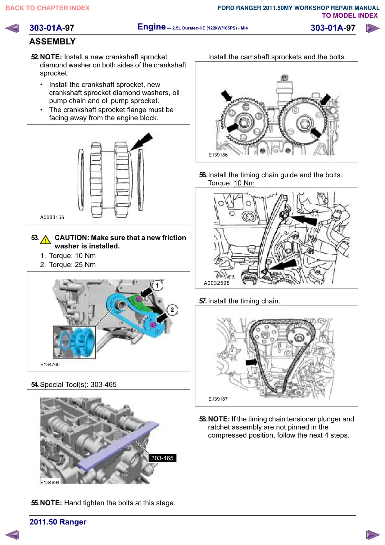
52.NOTE: Install a new crankshaft sprocket
diamond washer on both sides of the crankshaft
sprocket.
Install the crankshaft sprocket, new
crankshaft sprocket diamond washers, oil
pump chain and oil pump sprocket.
The crankshaft sprocket flange must be
facing away from the engine block.
A0083166
53.
CAUTION: Make sure that a new friction
washer is installed.
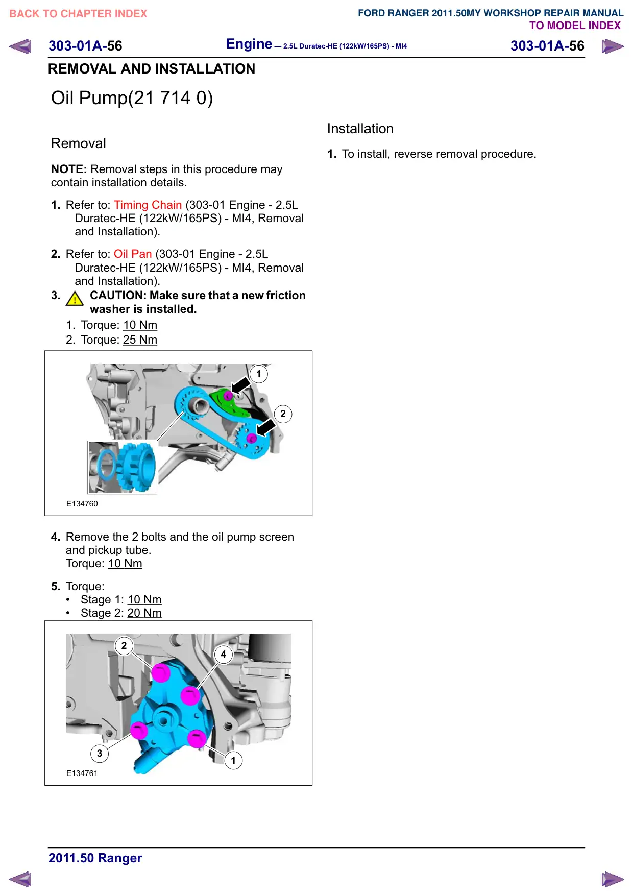
1. Torque: 10 Nm
2. Torque: 25 Nm
1
2
E134760
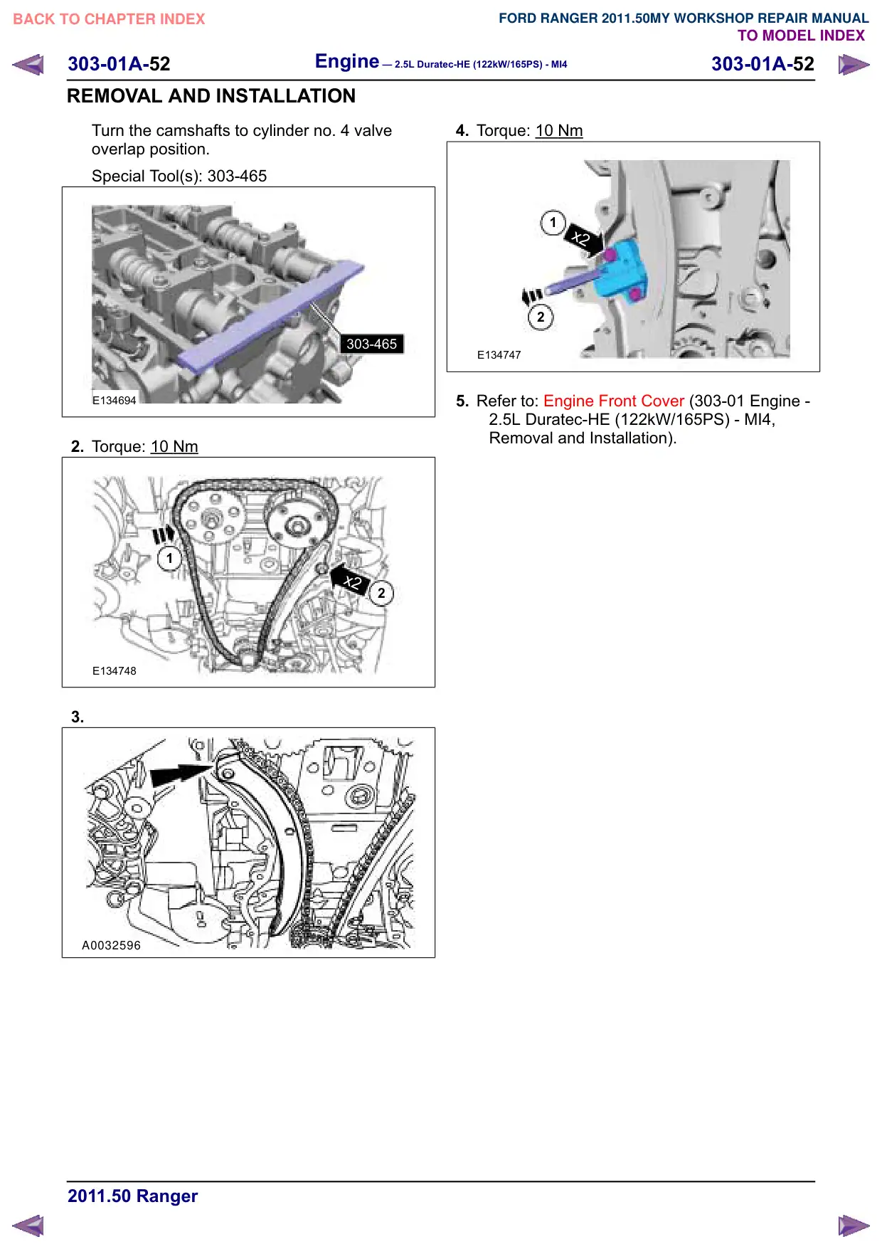
54.Special Tool(s): 303-465
303-465
E134694
55.NOTE: Hand tighten the bolts at this stage.
Install the camshaft sprockets and the bolts.
E139186
56.Install the timing chain guide and the bolts.
Torque: 10
Nm
A0032598
57.Install the timing chain.
E139187
58.NOTE: If the timing chain tensioner plunger and
ratchet assembly are not pinned in the
compressed position, follow the next 4 steps.
Engine – 2.5L Duratec-HE (122kW/165PS) - MI4
303-01A-98
303-01A-98
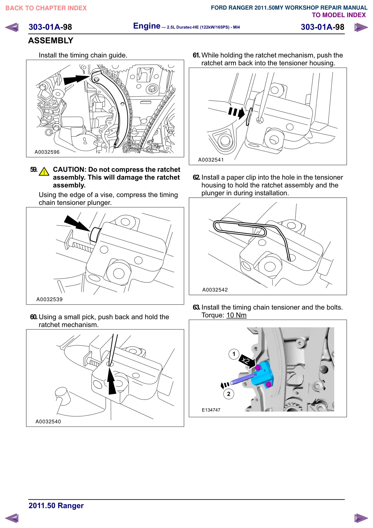
ASSEMBLY
Install the timing chain guide.
A0032596
59.
CAUTION: Do not compress the ratchet
assembly. This will damage the ratchet
assembly.
Using the edge of a vise, compress the timing
chain tensioner plunger.
A0032539
60.Using a small pick, push back and hold the
ratchet mechanism.
A0032540
61.While holding the ratchet mechanism, push the
ratchet arm back into the tensioner housing.
A0032541
62.Install a paper clip into the hole in the tensioner
housing to hold the ratchet assembly and the
plunger in during installation.
A0032542
63.Install the timing chain tensioner and the bolts.
Torque: 10 Nm
1
x2
2
E134747
303-01A-
Engine – 2.5L Duratec-HE (122kW/165PS) - MI4
303-01A-
ASSEMBLY
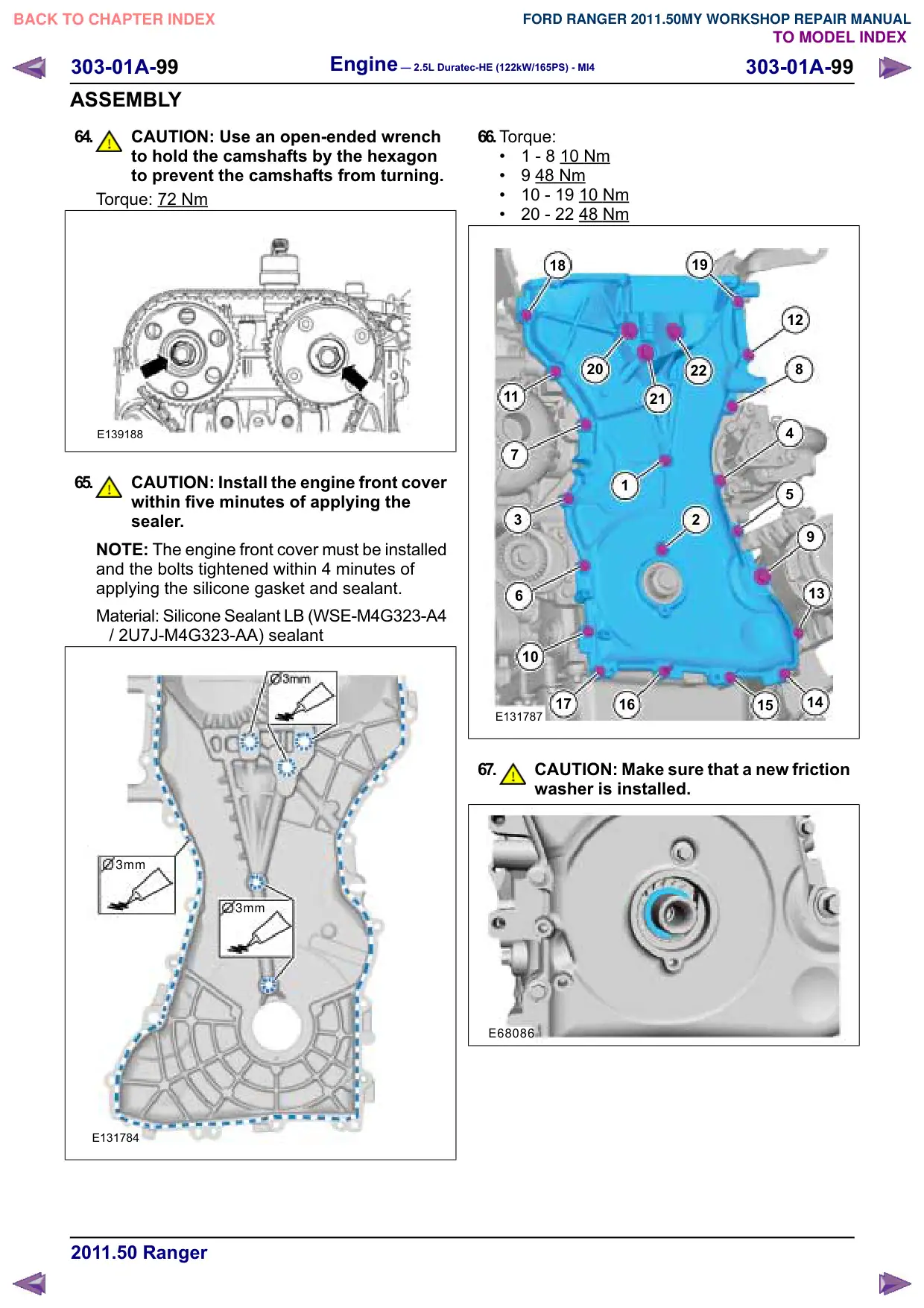
64.
CAUTION: Use an open-ended wrench
to hold the camshafts by the hexagon
to prevent the camshafts from turning.
Torque: 72 Nm
E139188
65.
CAUTION: Install the engine front cover
within five minutes of applying the
sealer.
NOTE: The engine front cover must be installed
and the bolts tightened within 4 minutes of
applying the silicone gasket and sealant.
Material: Silicone Sealant LB (WSE-M4G323-A4
/ 2U7J-M4G323-AA) sealant
3mm
3mm
E131784
66.Torque:
1 - 8 10 Nm
9 48 Nm
10 - 19 10 Nm
20 - 22 48 Nm
19
18
12
20
22
8
11
21
4
7
1
5
3
2
6
13
10
14
17
16
15
E131787
67.
CAUTION: Make sure that a new friction
washer is installed.
E68086
303-01A-100
Engine – 2.5L Duratec-HE (122kW/165PS) - MI4
303-01A-100
ASSEMBLY
68.Special Tool(s): 303-318
Torque: 50
Nm
303-318
E131777
69.Remove the Special Tool(s): 303-318
303-318
E131776
70.NOTE: Hand tighten the bolt at this stage.
Bolt M6 x 18 mm
E131756
71.
CAUTION: Make sure that a new bolt is
installed.
Special Tool(s): 303-1416
Torque:
Stage 1: 100
Nm
Stage 2: 90°
303-1416
E131740
72.Remove the 6 mm x 18 mm bolt.
E131758
73.Remove the Special Tool(s): 303-507
303-507
E131755
Engine – 2.5L Duratec-HE (122kW/165PS) - MI4
303-01A-101
303-01A-101
ASSEMBLY
74.Install the engine plug bolt.
Torque: 20
Nm
E131754
75.Remove the Special Tool(s): 303-465
303-465
E134694
76.NOTE: The valve cover must be secured within
4 minutes of silicone gasket application. If the
valve cover is not secured within 4 minutes, the
sealant must be removed and the sealing area
cleaned with metal surface prep.
Material: Silicone Sealant LB (WSE-M4G323-A4
/ 2U7J-M4G323-AA) sealant
E80569
77.NOTE: The gasket is to be reused unless
damaged.
Torque: 10
Nm
11
6
3
7
12
10
2
13
1
14
5
4
8
E131760
Engine – 2.5L Duratec-HE (122kW/165PS) - MI4
303-01A-108
303-01A-108
INSTALLATION
34.
x9
E131903
35.Torque: 30 Nm
1
x4
2
E128859
36.Refer to: Fuel System Pressure Release
(310-00 Fuel System - General Information -
2.5L Duratec-HE (122kW/165PS) - MI4,
General Procedures).
37.Refer to: Brake System Health and Safety
Precautions (100-00 General Information,
Description and Operation).
38.Refer to: Air Conditioning (A/C) System
Recovery, Evacuation and Charging (412-00
Climate Control System - General Information,
General Procedures).
39.Refer to: Starter Motor (303-06 Starting System
- 2.5L Duratec-HE (122kW/165PS) - MI4,
Removal and Installation).
40.Refer to: Lifting (100-02 Jacking and Lifting,
Description and Operation).
41.Refer to: Battery Disconnect and Connect
(414-01 Battery, Mounting and Cables,
General Procedures).
42.Refer to: Cooling System Draining, Filling and
Bleeding (303-03 Engine Cooling, General
Procedures).
303-01A-112
Engine – 2.5L Duratec-HE (122kW/165PS) - MI4
303-01A-112
INSTALLATION
x4
x4
x2
E138986
16.NOTE: Do not use metal scrapers, wire brushes,
power abrasive discs or other abrasive means
to clean the sealing surfaces. These tools can
cause scratches and gouges which can make
leak paths. Use a plastic scraping tool to remove
all traces of the old intake manifold gaskets.
NOTE: If the engine is repaired or replaced
because of upper engine failure, typically
including valve or piston damage, check the
intake manifold for metal debris. If metal debris
is found, install a new intake manifold. Failure
to follow these instructions can result in engine
damage.
NOTE: The gasket is to be reused unless
damage.
x3
x4
Clean the sealing surfaces and inspect the
gaskets. Install new gaskets if necessary.
Torque: 19
Nm
x5
E138985
Engine – 2.5L Duratec-HE (122kW/165PS) - MI4
303-01A-115
303-01A-115
INSTALLATION
29.NOTE: The cone on the special tool must only
be tightened finger tight to prevent damage to
the clutch disc.
Special Tool(s): 308-204
308-204
E129961
30.NOTE: Check the pilot bearing for damage.
Replace it, if necessary.
Refer to: Pilot Bearing - 2.5L Duratec-HE
(122kW/165PS) - MI4 (308-01 Clutch -
Vehicles With: 5-Speed Manual Transmission
- MT75, Removal and Installation).
31.NOTE: Only tighten the bolt finger tight at this
stage.
Special Tool(s): 308-204
308-204
E129962
32.Special Tool(s): 308-204
Torque: 30 Nm
6
1
4
308-204
3
2
5
E129963
33.Remove the Special Tool(s): 308-204
2
1
308-204
E129984