Manual Transmission/Transaxle – Vehicles With: 5-Speed
308-03A-4
308-03A-4
Manual Transmission - MT75
DESCRIPTION AND OPERATION
The MT - 75 manual transmission is a “ three -
shaft transmission".
MT - 75 means:
œ M: Manual.
œ T: Transmission
œ 75: Distance between main shaft and counter
shaft in mm.
The aluminum transmission housing consists of
two closed sections. The reinforcing ribs on the
transmission housing have been revised to reduce
noise and vibration.
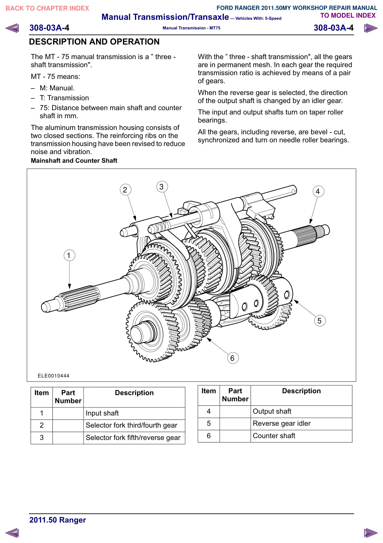
Mainshaft and Counter Shaft
3
2
1
ELE0010444
Item
Part
Description
Number
1
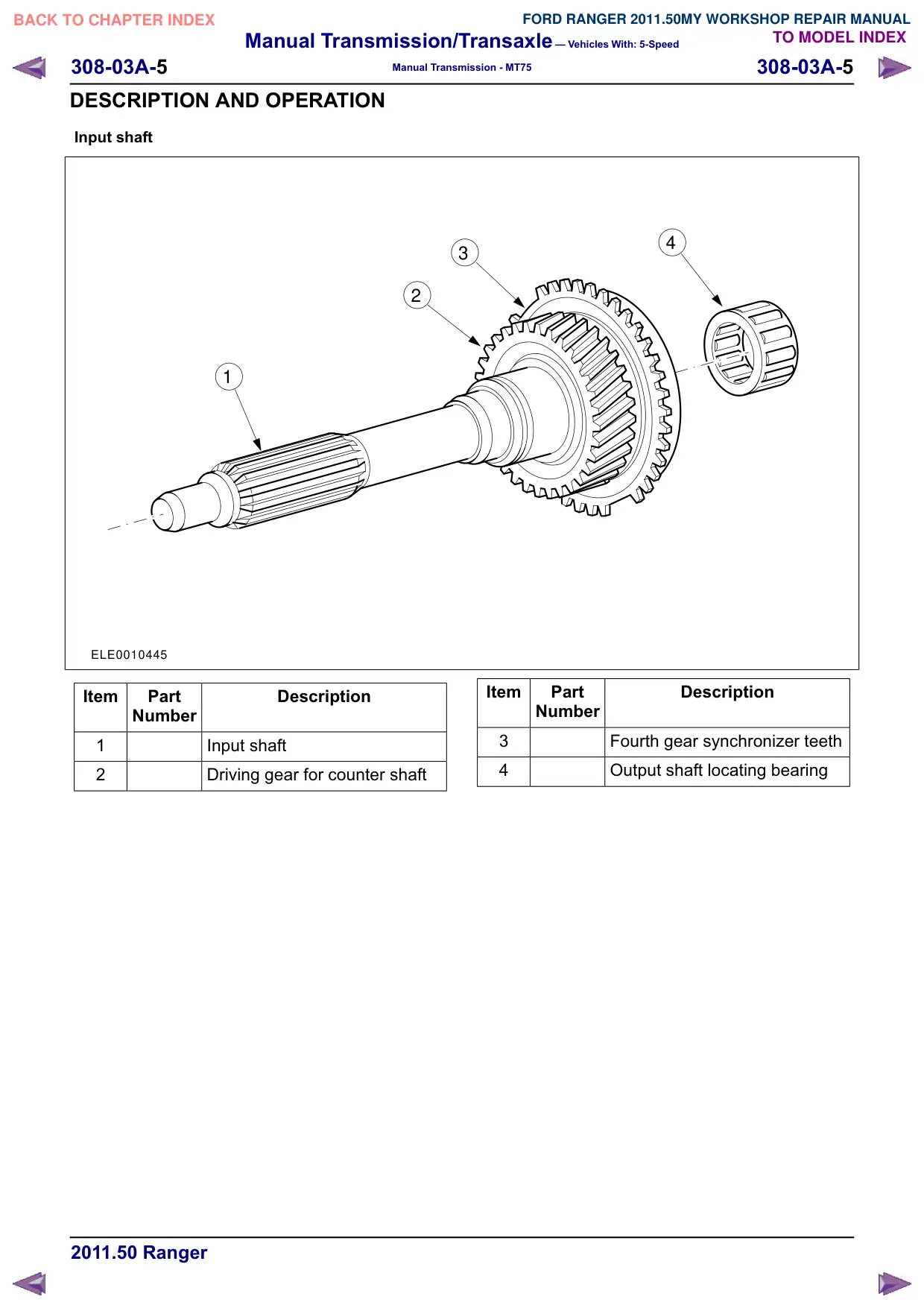
Input shaft
2
Selector fork third/fourth gear
3
Selector fork fifth/reverse gear
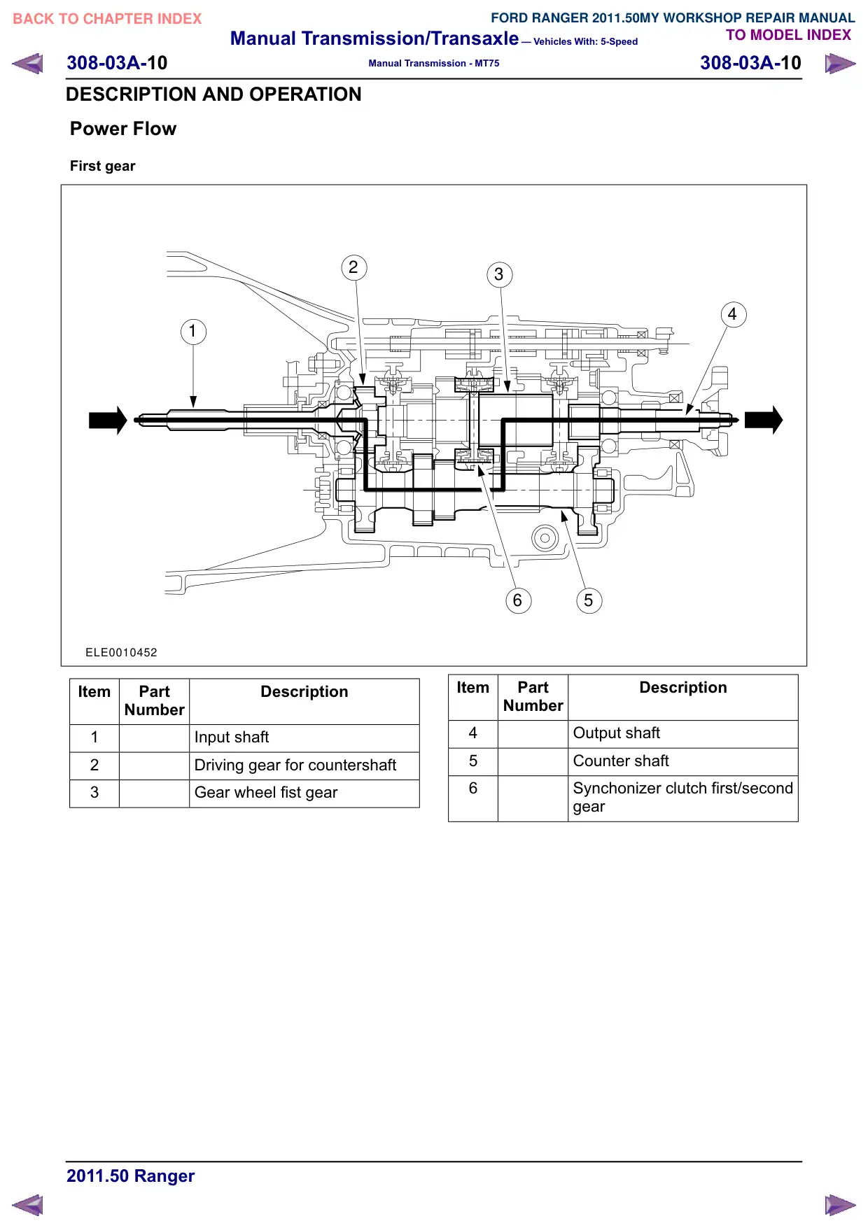
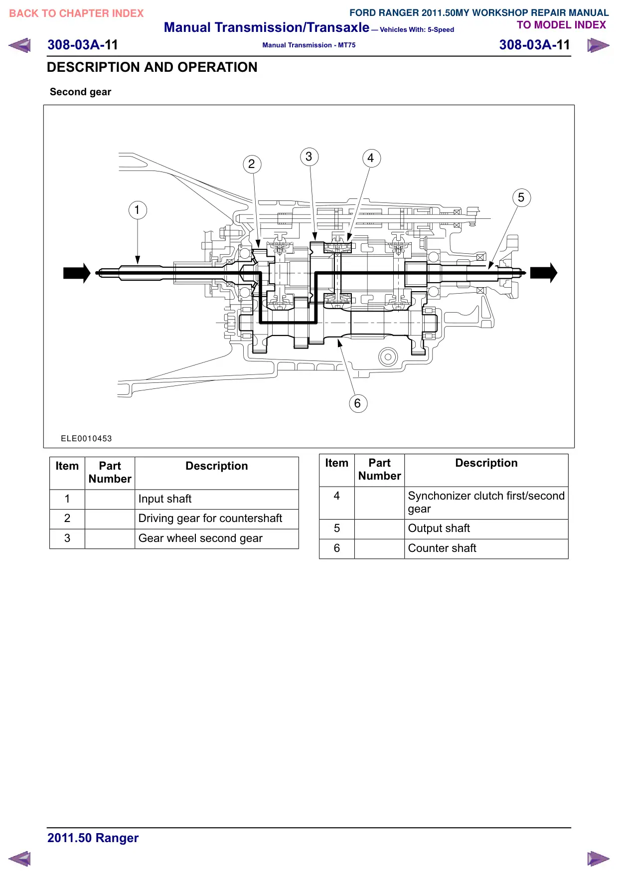
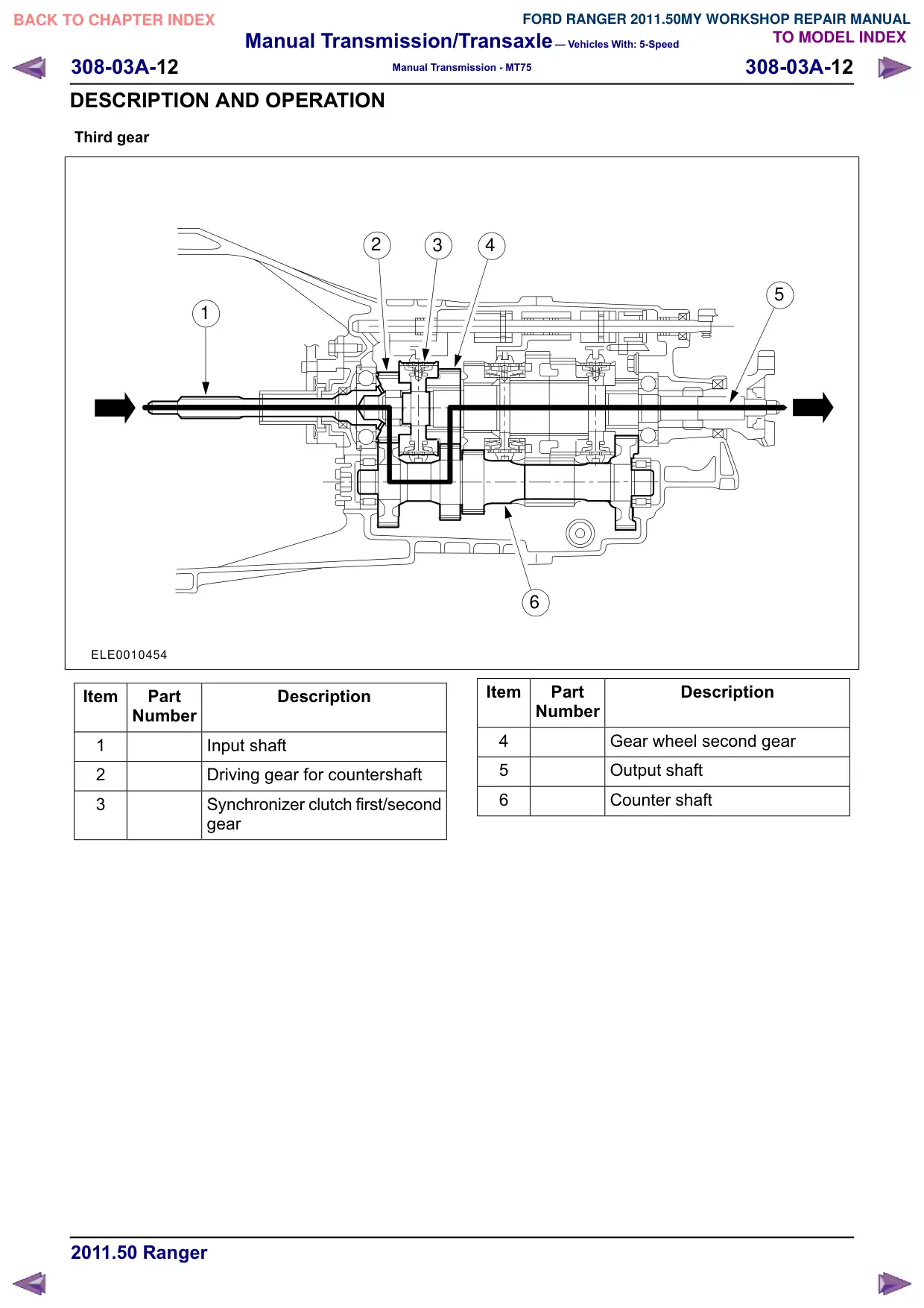
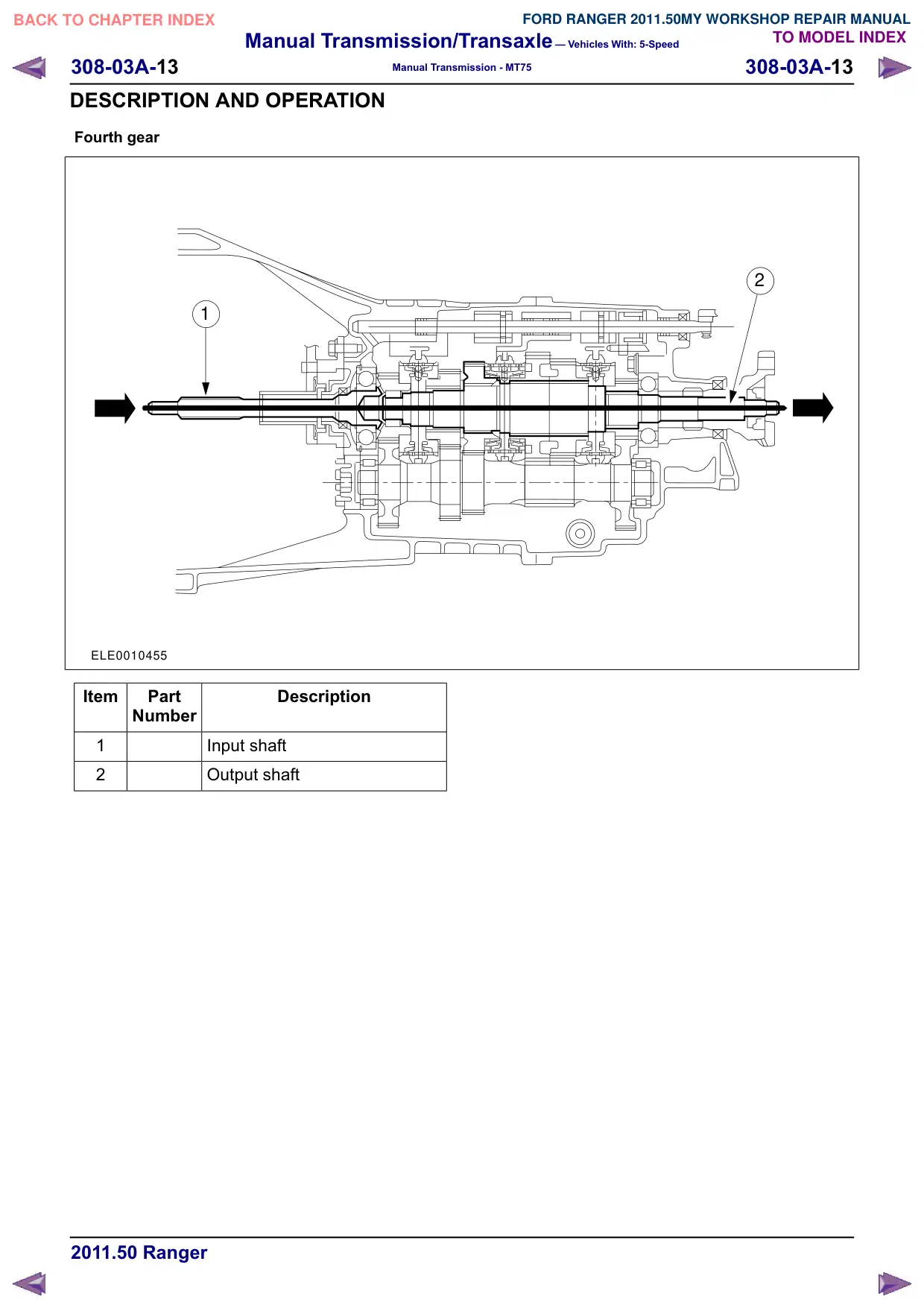
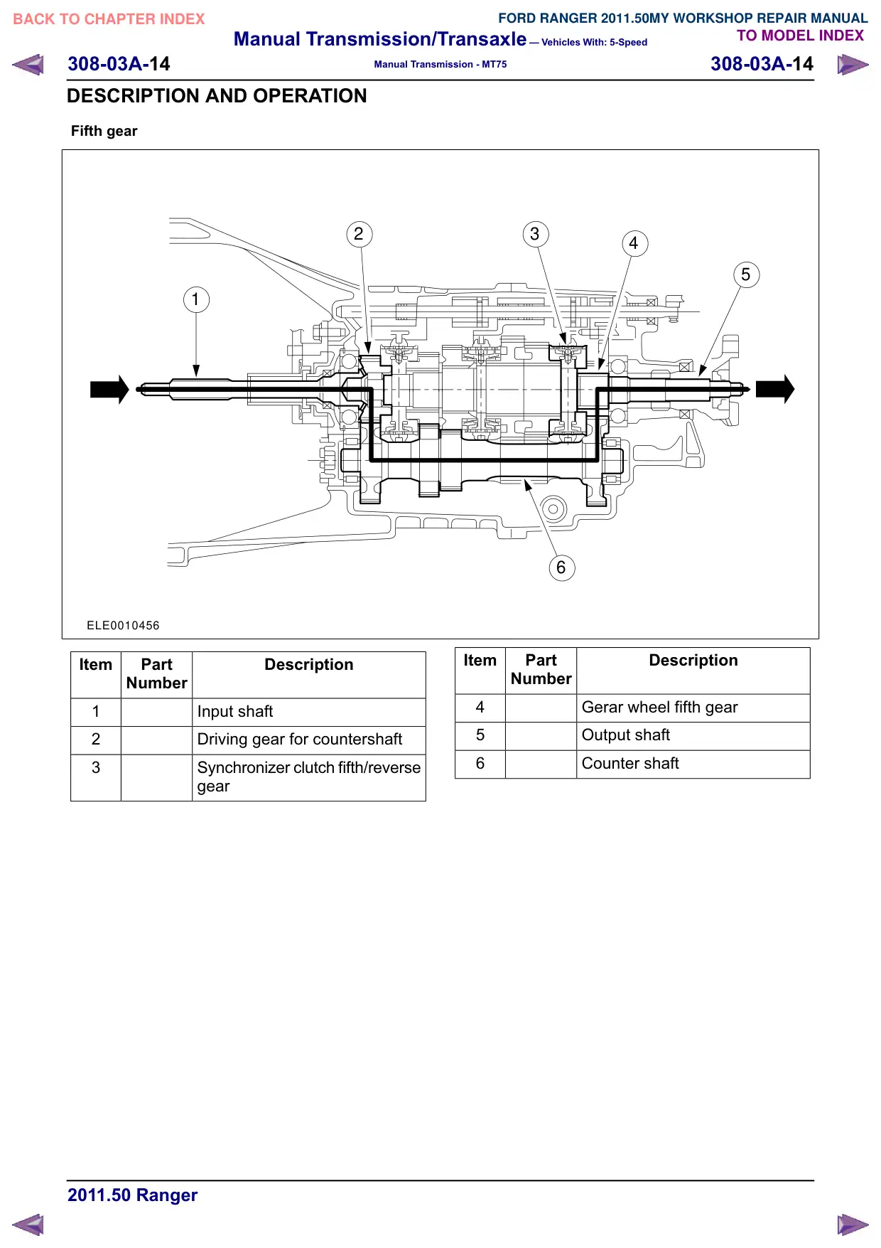
With the “ three - shaft transmission", all the gears
are in permanent mesh. In each gear the required
transmission ratio is achieved by means of a pair
of gears.
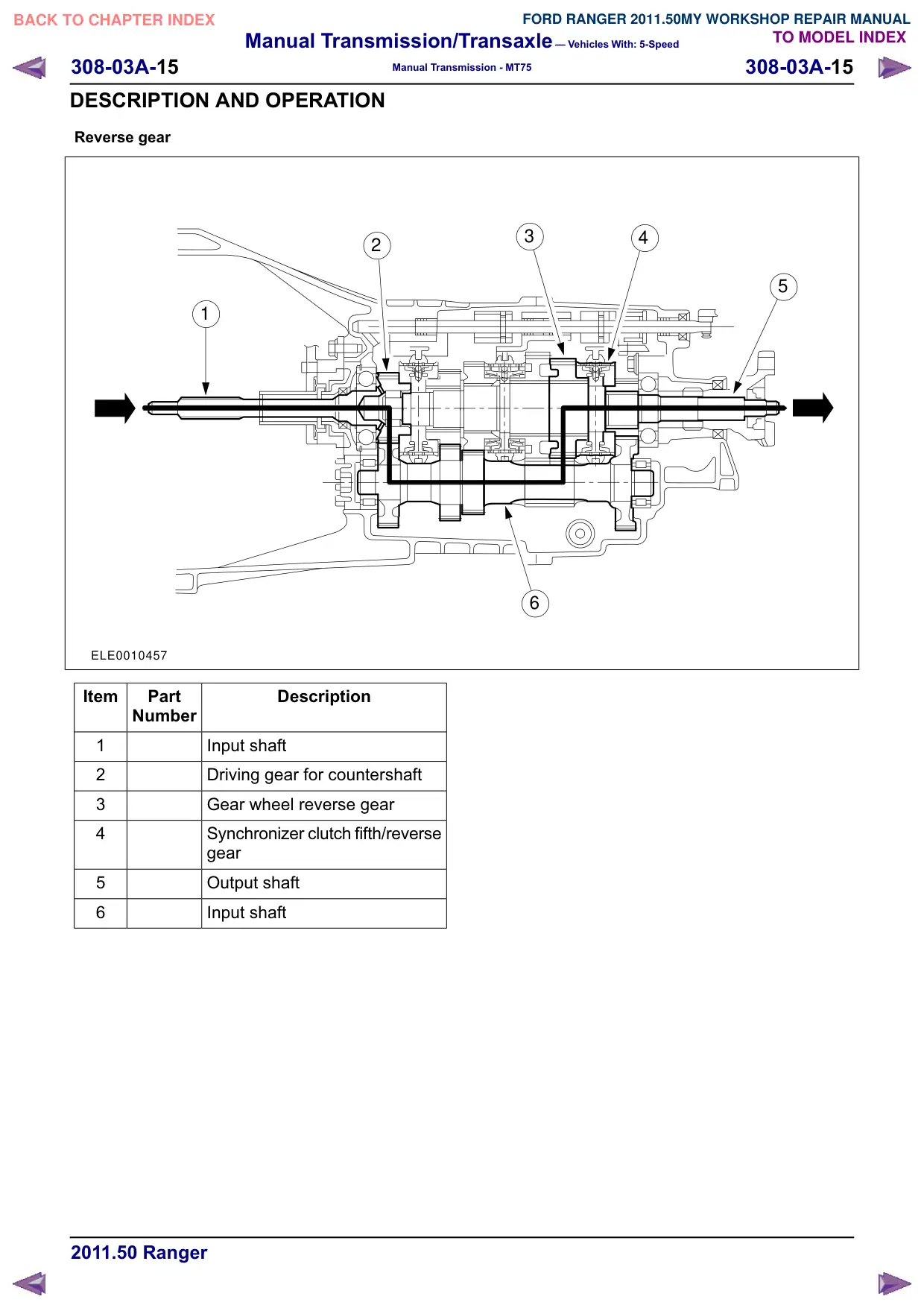
When the reverse gear is selected, the direction
of the output shaft is changed by an idler gear.
The input and output shafts turn on taper roller
bearings.
All the gears, including reverse, are bevel - cut,
synchronized and turn on needle roller bearings.
4
5
6
Item
Part
Description
Number
4
Output shaft
5
Reverse gear idler
6
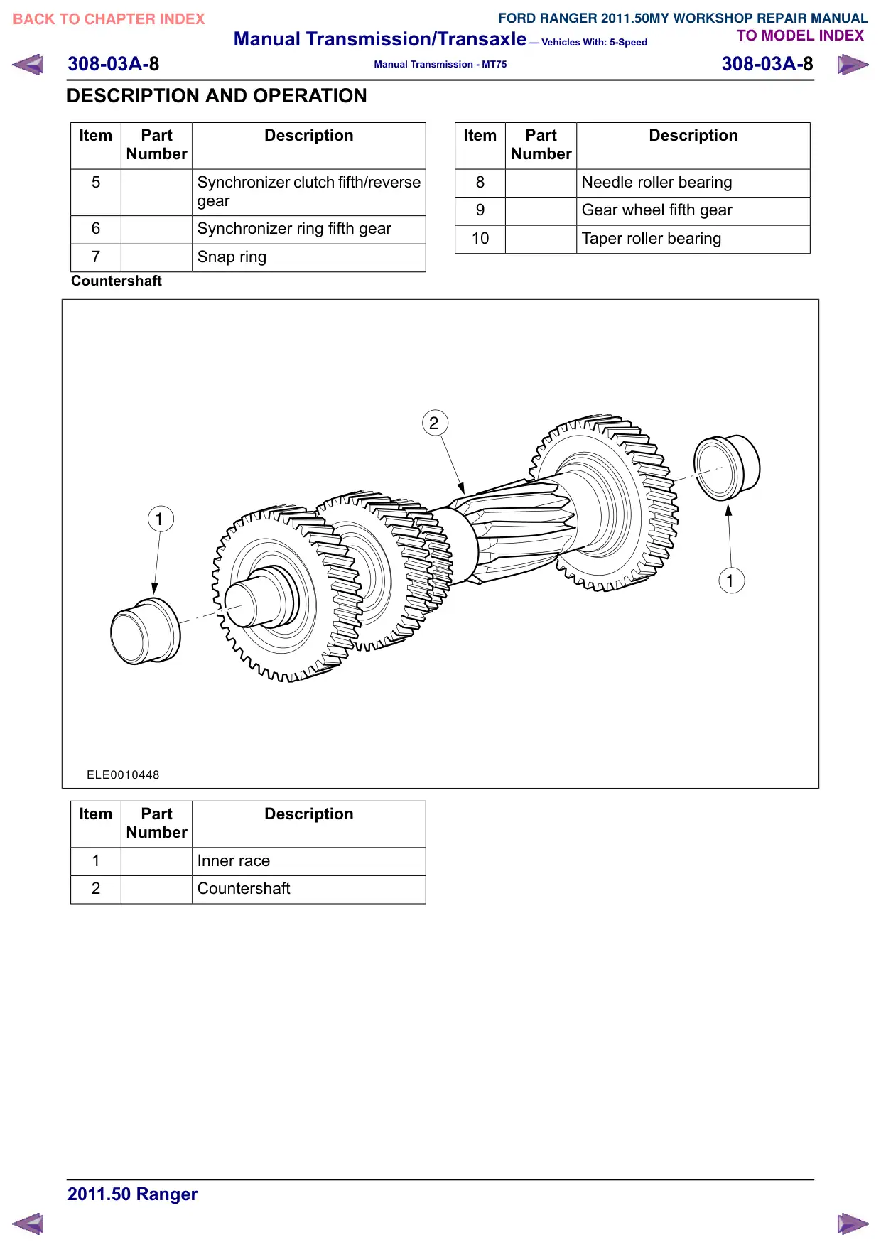
Counter shaft
Manual Transmission/Transaxle – Vehicles With: 5-Speed
308-03A-16
308-03A-16
Manual Transmission - MT75
GENERAL PROCEDURES
Transmission Draining and Filling
1. Information not available at this time.
Manual Transmission/Transaxle – Vehicles With: 5-Speed
308-03A-27
308-03A-27
Manual Transmission - MT75
DISASSEMBLY
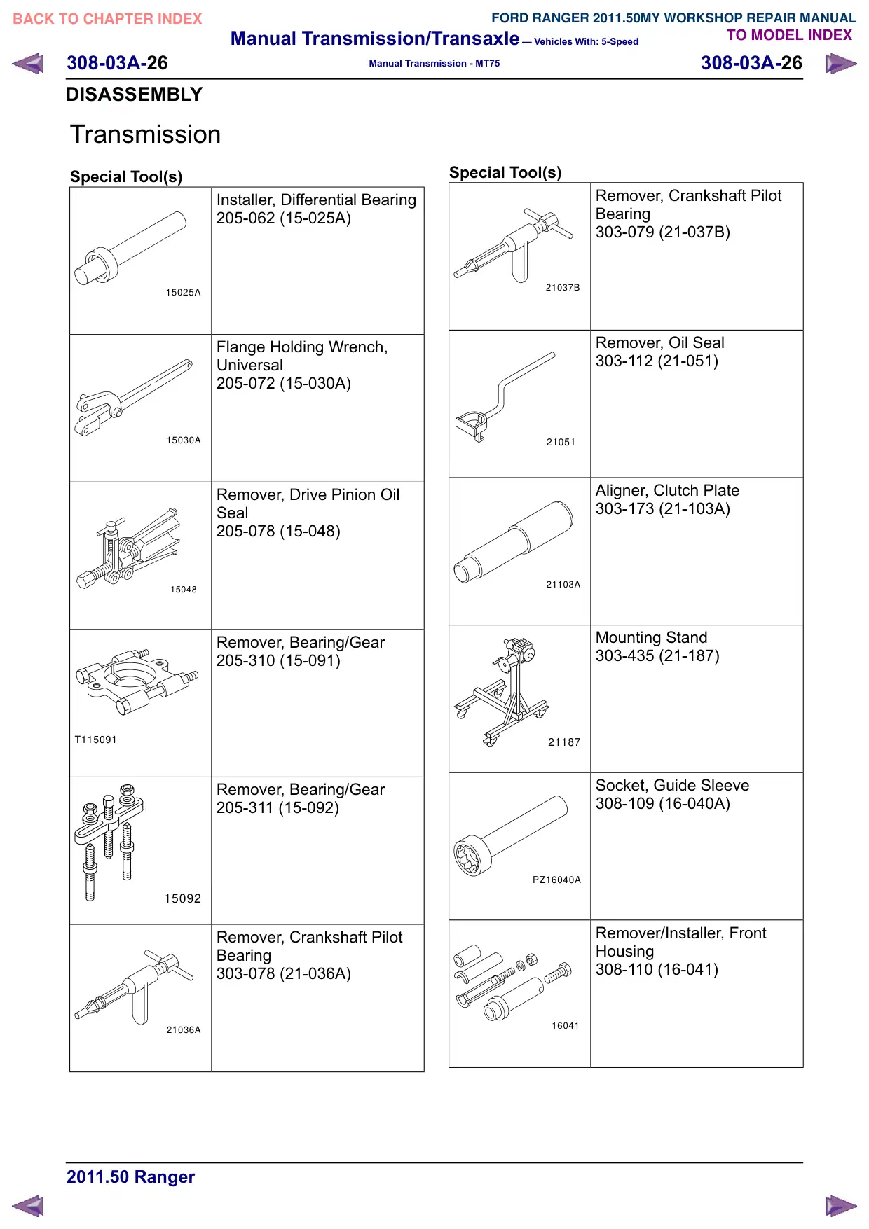
Special Tool(s)
Mounting Bracket for 303-435
308-114 (16-045)
16045
Mounting Brackets for
308-114
308-114-01 (16-045-01)
30811401
Remover, Slider
308-652
E77040
Disassembly
All vehicles
NOTE: All the bearings are paired and must not
be mixed.
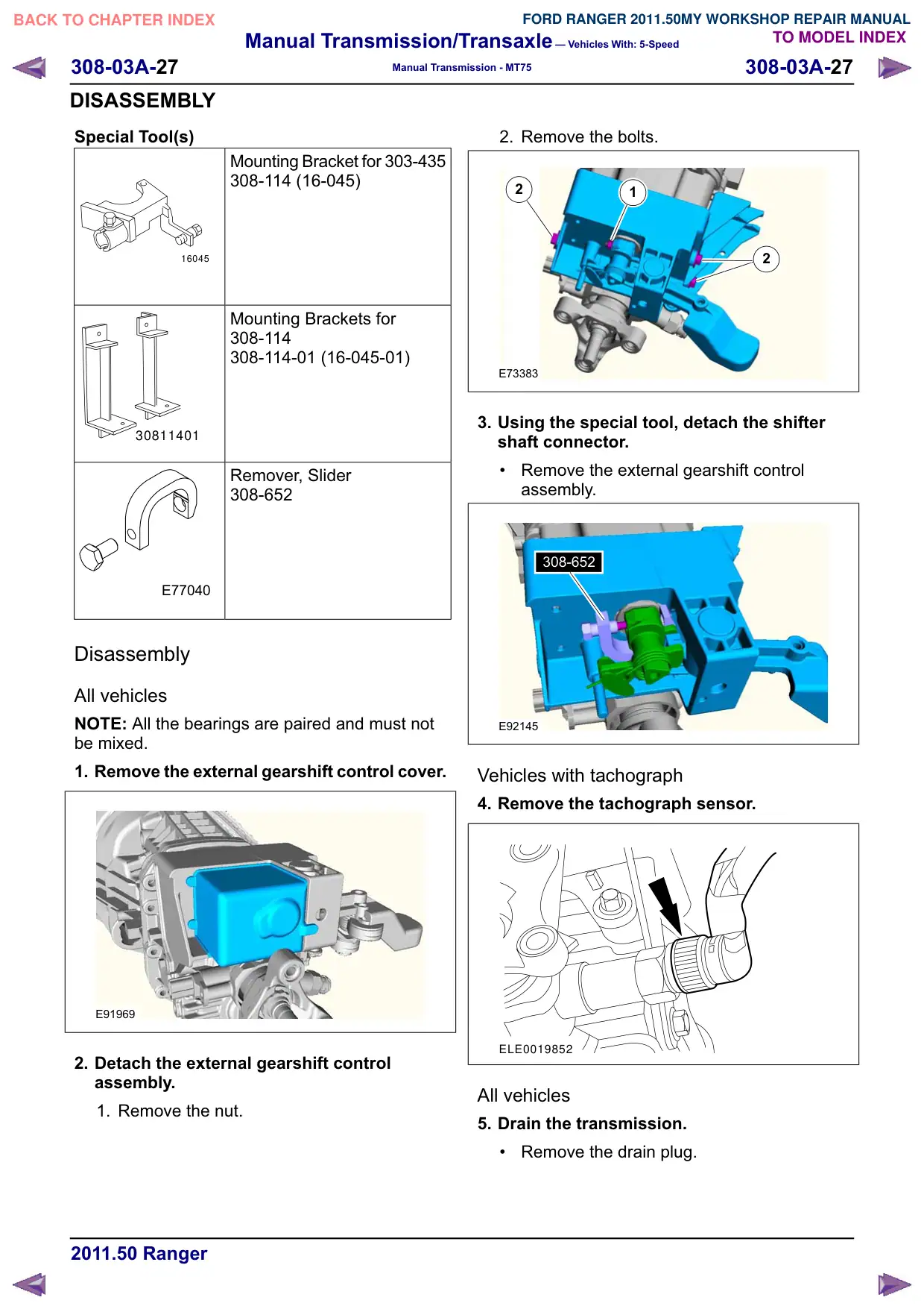
1. Remove the external gearshift control cover.
E91969
2. Detach the external gearshift control
assembly.
1. Remove the nut.
2. Remove the bolts.
2
1
2
E73383
3. Using the special tool, detach the shifter
shaft connector.
Remove the external gearshift control
assembly.
308-652
308-652
E92145
Vehicles with tachograph
4. Remove the tachograph sensor.
ELE0019852
All vehicles
5. Drain the transmission.
Remove the drain plug.
Manual Transmission/Transaxle – Vehicles With: 5-Speed
308-03A-28
308-03A-28
Manual Transmission - MT75
DISASSEMBLY
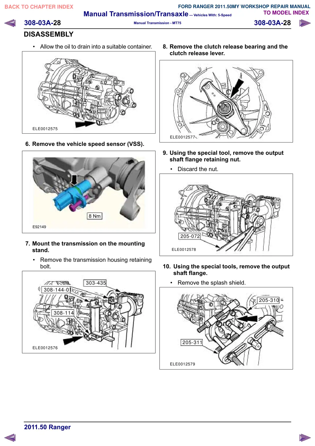
Allow the oil to drain into a suitable container.
ELE0012575
6. Remove the vehicle speed sensor (VSS).
8 Nm
E92149
7. Mount the transmission on the mounting
stand.
Remove the transmission housing retaining
bolt.
303-435
308-144-01
308-114
ELE0012576
8. Remove the clutch release bearing and the
clutch release lever.
ELE0012577
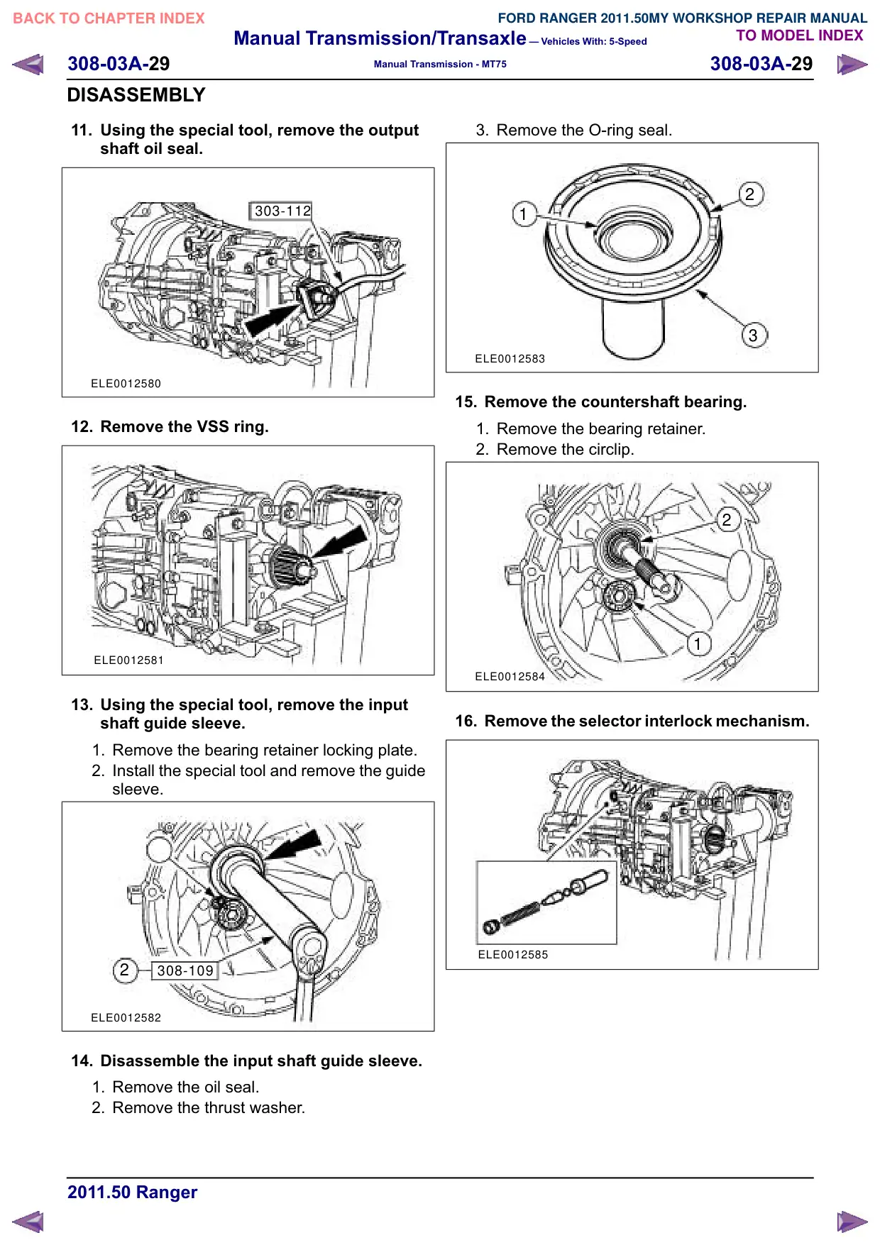
9. Using the special tool, remove the output
shaft flange retaining nut.
Discard the nut.
205-072
ELE0012578
10. Using the special tools, remove the output
shaft flange.
Remove the splash shield.
205-310
205-311
ELE0012579
Manual Transmission/Transaxle – Vehicles With: 5-Speed
308-03A-30
308-03A-30
Manual Transmission - MT75
DISASSEMBLY
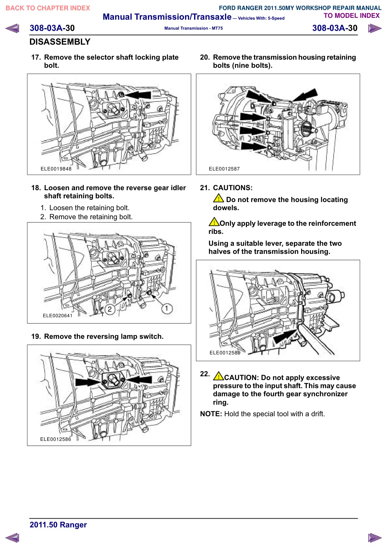
17. Remove the selector shaft locking plate
bolt.
ELE0019848
18. Loosen and remove the reverse gear idler
shaft retaining bolts.
1. Loosen the retaining bolt.
2. Remove the retaining bolt.
2
1
ELE0020641
19. Remove the reversing lamp switch.
ELE0012586
20. Remove the transmission housing retaining
bolts (nine bolts).
ELE0012587
21. CAUTIONS:
Do not remove the housing locating
dowels.
Only apply leverage to the reinforcement
ribs.
Using a suitable lever, separate the two
halves of the transmission housing.
ELE0012589
22.
CAUTION: Do not apply excessive
pressure to the input shaft. This may cause
damage to the fourth gear synchronizer
ring.
NOTE: Hold the special tool with a drift.
Manual Transmission/Transaxle – Vehicles With: 5-Speed
308-03A-31
308-03A-31
Manual Transmission - MT75
DISASSEMBLY
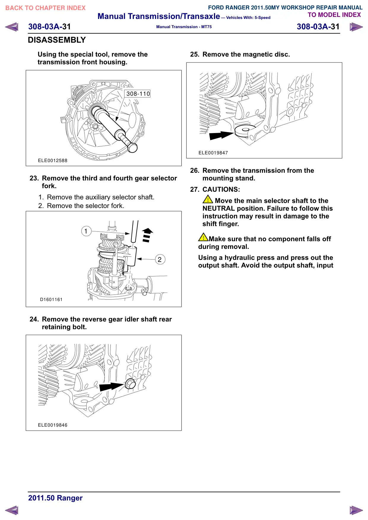
Using the special tool, remove the
transmission front housing.
308-110
ELE0012588
23. Remove the third and fourth gear selector
fork.
1. Remove the auxiliary selector shaft.
2. Remove the selector fork.
1
2
D1601161
24. Remove the reverse gear idler shaft rear
retaining bolt.
ELE0019846
25. Remove the magnetic disc.
ELE0019847
26. Remove the transmission from the
mounting stand.
27. CAUTIONS:
Move the main selector shaft to the
NEUTRAL position. Failure to follow this
instruction may result in damage to the
shift finger.
Make sure that no component falls off
during removal.
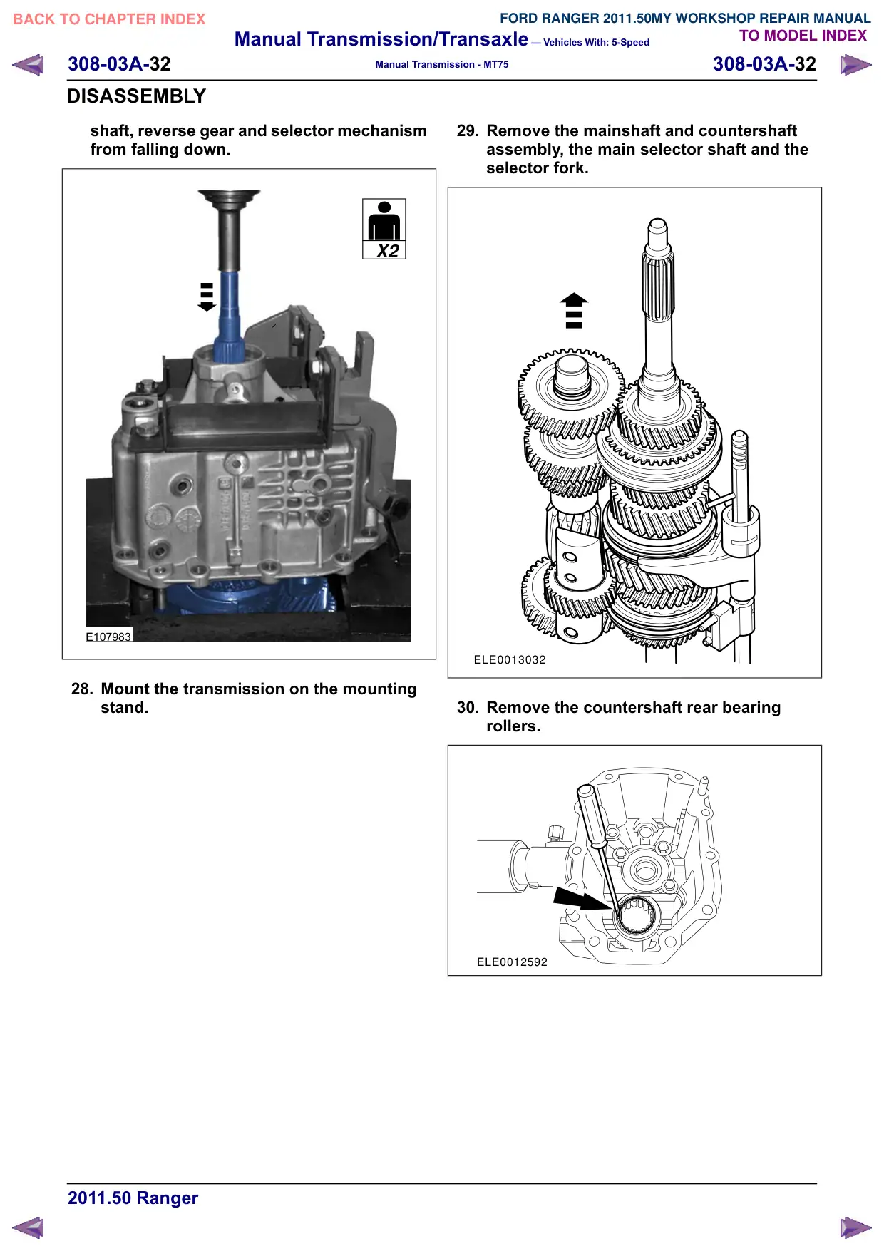
Using a hydraulic press and press out the
output shaft. Avoid the output shaft, input
Manual Transmission/Transaxle – Vehicles With: 5-Speed
308-03A-32
308-03A-32
Manual Transmission - MT75
DISASSEMBLY
shaft, reverse gear and selector mechanism
from falling down.
X2
2 X
2
E107983
28. Mount the transmission on the mounting
stand.
29. Remove the mainshaft and countershaft
assembly, the main selector shaft and the
selector fork.
ELE0013032
30. Remove the countershaft rear bearing
rollers.
ELE0012592
Manual Transmission/Transaxle – Vehicles With: 5-Speed
308-03A-33
308-03A-33
Manual Transmission - MT75
DISASSEMBLY
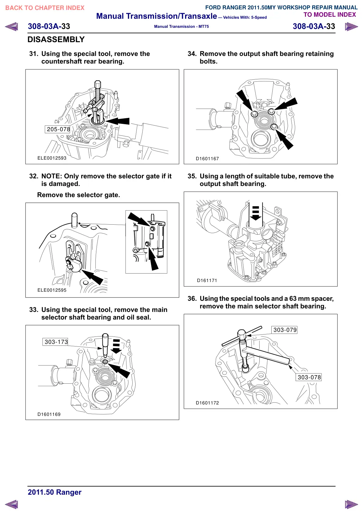
31. Using the special tool, remove the
countershaft rear bearing.
205-078
ELE0012593
32. NOTE: Only remove the selector gate if it
is damaged.
Remove the selector gate.
ELE0012595
33. Using the special tool, remove the main
selector shaft bearing and oil seal.
303-173
D1601169
34. Remove the output shaft bearing retaining
bolts.
D1601167
35. Using a length of suitable tube, remove the
output shaft bearing.
D161171
36. Using the special tools and a 63 mm spacer,
remove the main selector shaft bearing.
303-079
303-078
D1601172
Manual Transmission/Transaxle – Vehicles With: 5-Speed
308-03A-34
308-03A-34
Manual Transmission - MT75
DISASSEMBLY
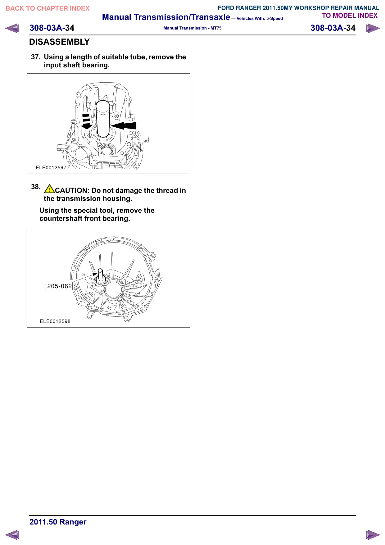
37. Using a length of suitable tube, remove the
input shaft bearing.
ELE0012597
38.
CAUTION: Do not damage the thread in
the transmission housing.
Using the special tool, remove the
countershaft front bearing.
205-062
ELE0012598
Manual Transmission/Transaxle – Vehicles With: 5-Speed
308-03A-35
308-03A-35
Manual Transmission - MT75
DISASSEMBLY AND ASSEMBLY OF SUBASSEMBLIES
Input Shaft
Disassembly
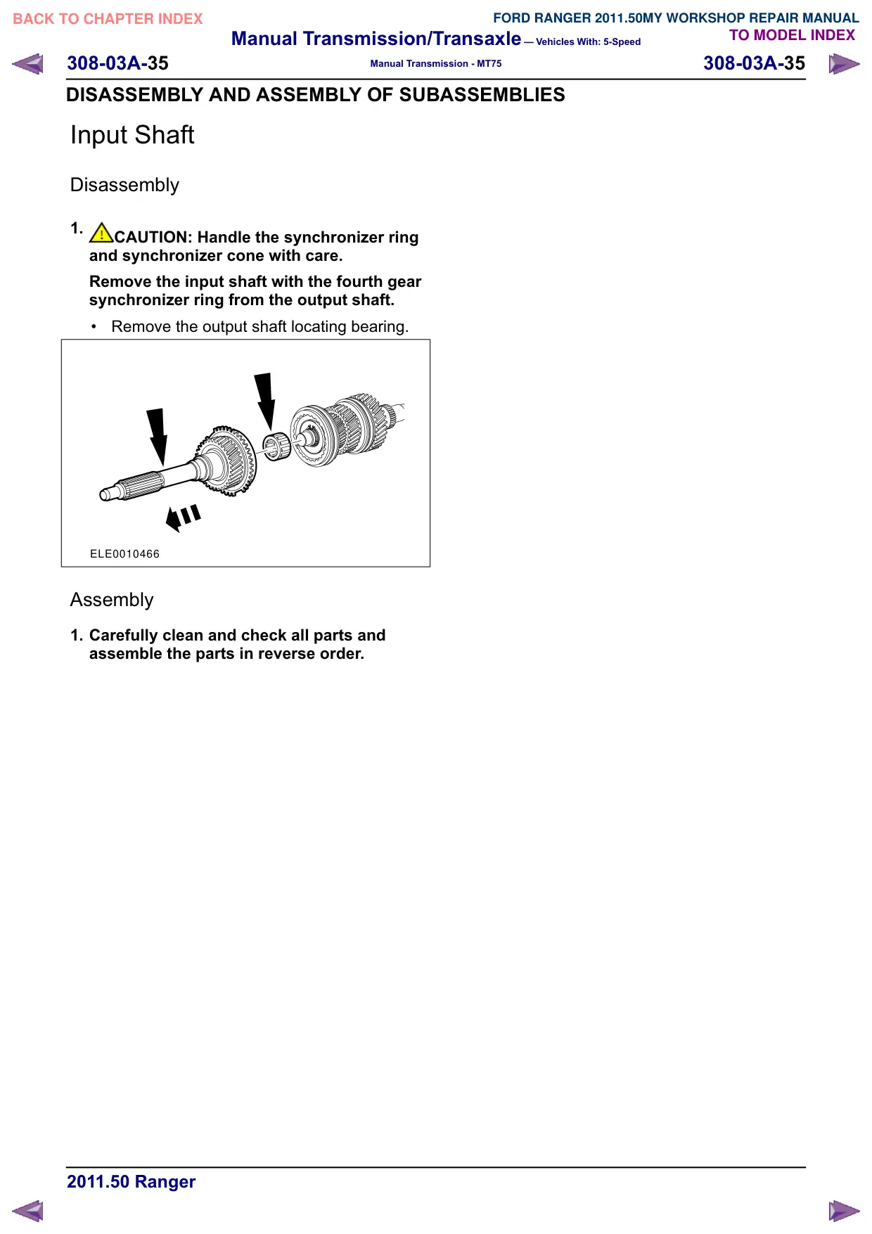
1.
CAUTION: Handle the synchronizer ring
and synchronizer cone with care.
Remove the input shaft with the fourth gear
synchronizer ring from the output shaft.
Remove the output shaft locating bearing.
ELE0010466
Assembly
1. Carefully clean and check all parts and
assemble the parts in reverse order.
Manual Transmission/Transaxle – Vehicles With: 5-Speed
308-03A-36
308-03A-36
Manual Transmission - MT75
DISASSEMBLY AND ASSEMBLY OF SUBASSEMBLIES
Output Shaft
Special Tool(s)
Remover, Mainshaft Needle
Bearing Sleeve
308 - 191 (16 - 056)
16056
General Equipment
Hot air gun
Materials
Name
Specification
Manual transmission
WSD - M2C200 - C
fluid
Disassembly
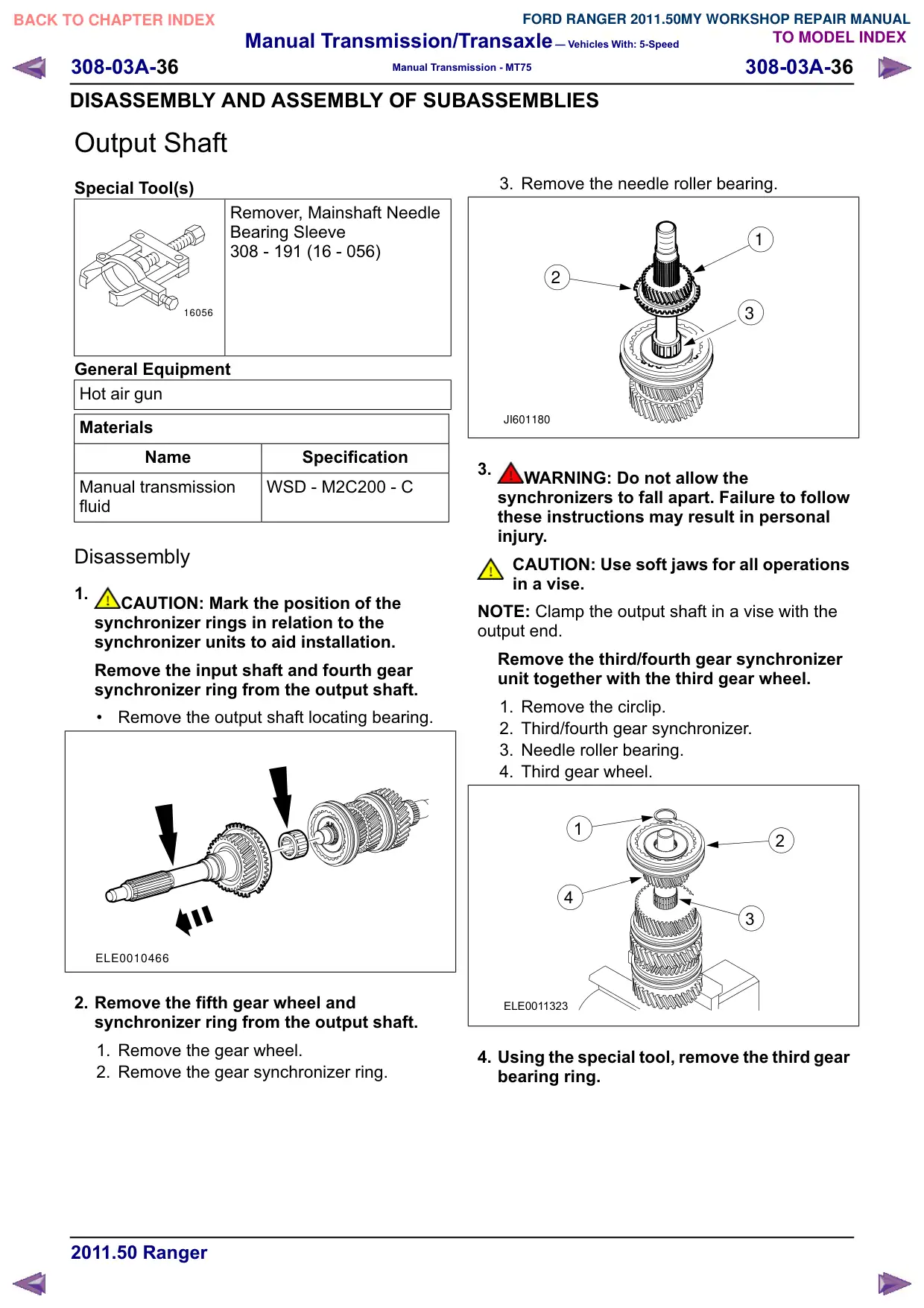
1.
CAUTION: Mark the position of the
synchronizer rings in relation to the
synchronizer units to aid installation.
Remove the input shaft and fourth gear
synchronizer ring from the output shaft.
Remove the output shaft locating bearing.
ELE0010466
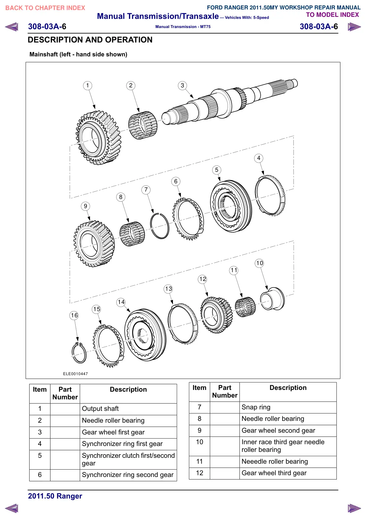
2. Remove the fifth gear wheel and
synchronizer ring from the output shaft.
1. Remove the gear wheel.
2. Remove the gear synchronizer ring.
3. Remove the needle roller bearing.
1
2
3
JI601180
3.
WARNING: Do not allow the
synchronizers to fall apart. Failure to follow
these instructions may result in personal
injury.
CAUTION: Use soft jaws for all operations
in a vise.
NOTE: Clamp the output shaft in a vise with the
output end.
Remove the third/fourth gear synchronizer
unit together with the third gear wheel.
1. Remove the circlip.
2. Third/fourth gear synchronizer.
3. Needle roller bearing.
4. Third gear wheel.
1
2
4
3
ELE0011323
4. Using the special tool, remove the third gear
bearing ring.
Manual Transmission/Transaxle – Vehicles With: 5-Speed
308-03A-37
308-03A-37
Manual Transmission - MT75
DISASSEMBLY AND ASSEMBLY OF SUBASSEMBLIES
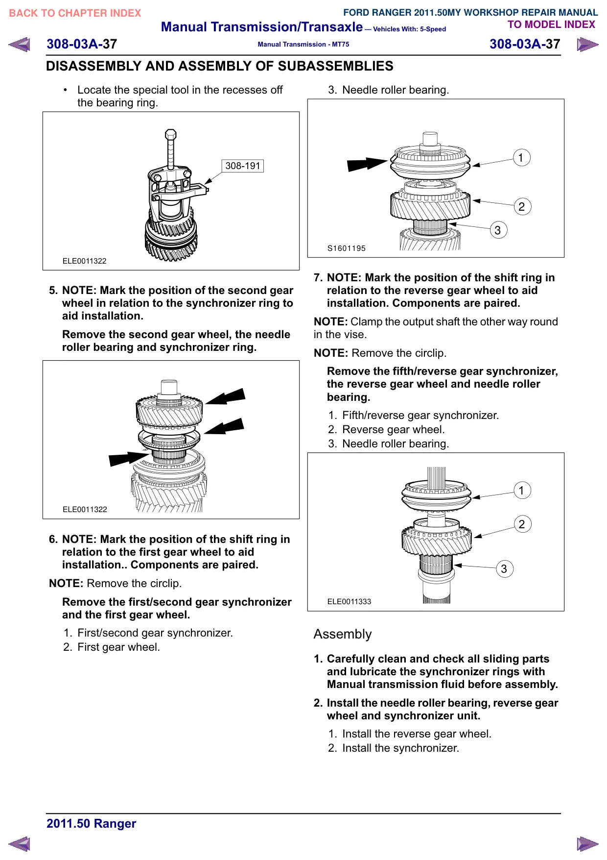
Locate the special tool in the recesses off
the bearing ring.
308-191
ELE0011322
5. NOTE: Mark the position of the second gear
wheel in relation to the synchronizer ring to
aid installation.
Remove the second gear wheel, the needle
roller bearing and synchronizer ring.
ELE0011322
6. NOTE: Mark the position of the shift ring in
relation to the first gear wheel to aid
installation.. Components are paired.
NOTE: Remove the circlip.
Remove the first/second gear synchronizer
and the first gear wheel.
1. First/second gear synchronizer.
2. First gear wheel.
3. Needle roller bearing.
1
2
3
S1601195
7. NOTE: Mark the position of the shift ring in
relation to the reverse gear wheel to aid
installation. Components are paired.
NOTE: Clamp the output shaft the other way round
in the vise.
NOTE: Remove the circlip.
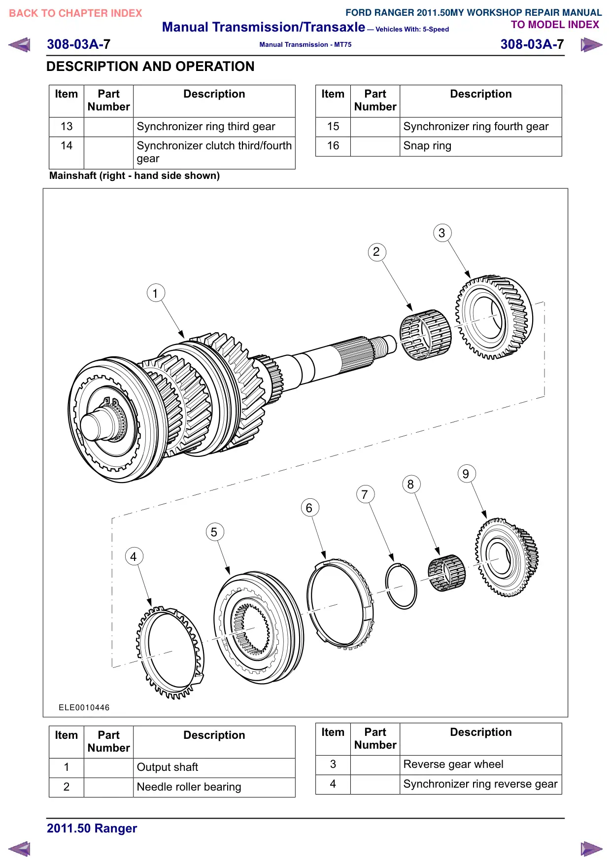
Remove the fifth/reverse gear synchronizer,
the reverse gear wheel and needle roller
bearing.
1. Fifth/reverse gear synchronizer.
2. Reverse gear wheel.
3. Needle roller bearing.
1
2
3
ELE0011333
Assembly
1. Carefully clean and check all sliding parts
and lubricate the synchronizer rings with
Manual transmission fluid before assembly.
2. Install the needle roller bearing, reverse gear
wheel and synchronizer unit.
1. Install the reverse gear wheel.
2. Install the synchronizer.
Manual Transmission/Transaxle – Vehicles With: 5-Speed
308-03A-38
308-03A-38
Manual Transmission - MT75
DISASSEMBLY AND ASSEMBLY OF SUBASSEMBLIES
3. Install the snap ring.
3
2
1
ELJ1601694
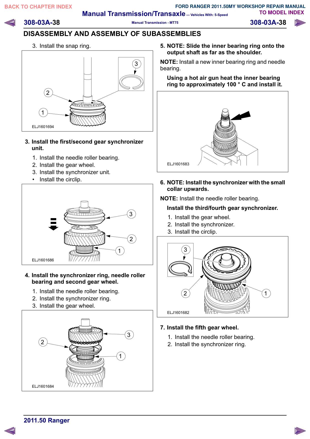
3. Install the first/second gear synchronizer
unit.
1. Install the needle roller bearing.
2. Install the gear wheel.
3. Install the synchronizer unit.
Install the circlip.
3
2
1
ELJ1601686
4. Install the synchronizer ring, needle roller
bearing and second gear wheel.
1. Install the needle roller bearing.
2. Install the synchronizer ring.
3. Install the gear wheel.
3
2
1
ELJ1601684
5. NOTE: Slide the inner bearing ring onto the
output shaft as far as the shoulder.
NOTE: Install a new inner bearing ring and needle
bearing.
Using a hot air gun heat the inner bearing
ring to approximately 100 ° C and install it.
ELJ1601683
6. NOTE: Install the synchronizer with the small
collar upwards.
NOTE: Install the needle roller bearing.
Install the third/fourth gear synchronizer.
1. Install the gear wheel.
2. Install the synchronizer.
3. Install the circlip.
3
2
1
ELJ1601682
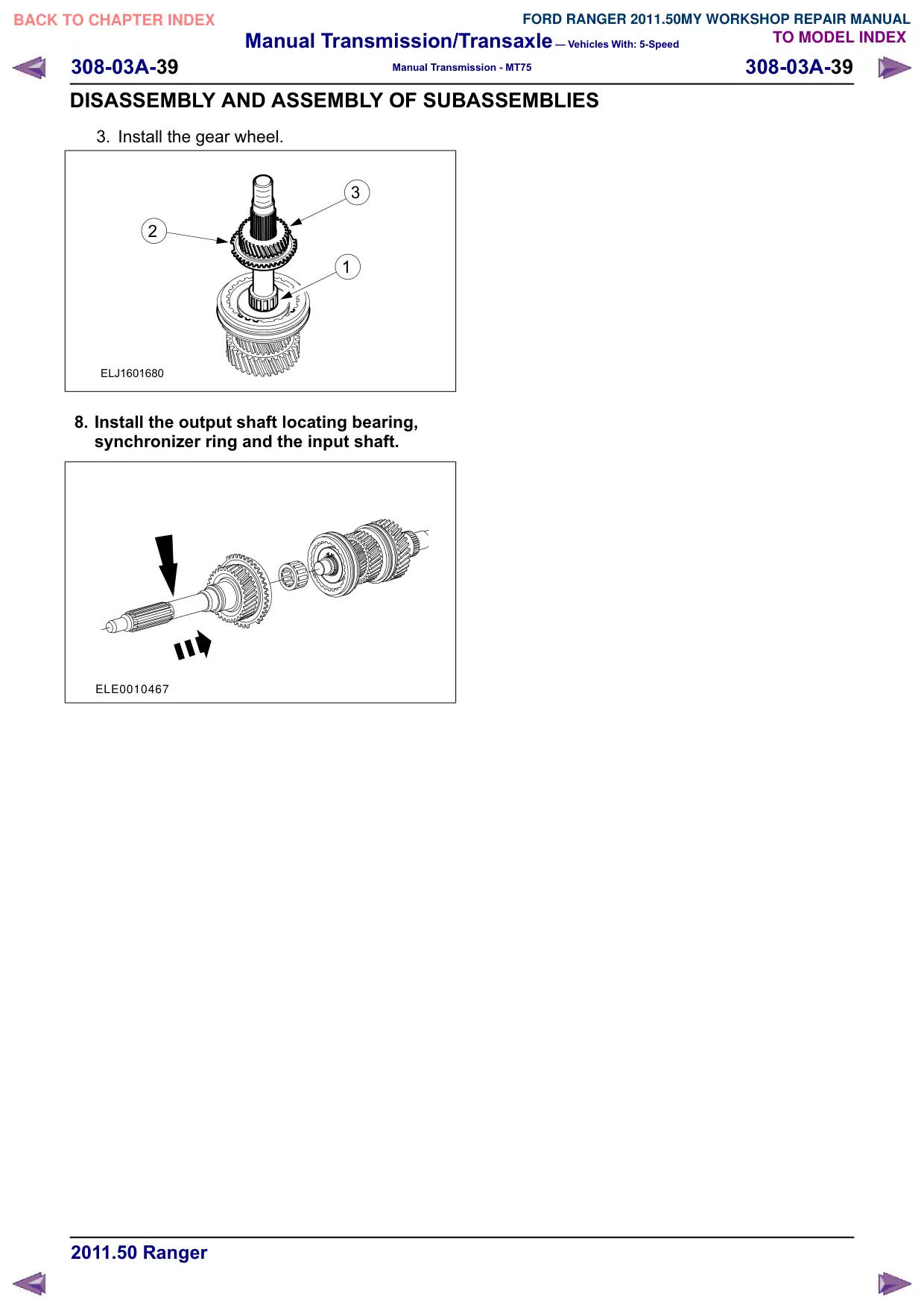
7. Install the fifth gear wheel.
1. Install the needle roller bearing.
2. Install the synchronizer ring.
Manual Transmission/Transaxle – Vehicles With: 5-Speed
308-03A-40
308-03A-40
Manual Transmission - MT75
DISASSEMBLY AND ASSEMBLY OF SUBASSEMBLIES
Countershaft
Special Tool(s)
Remover, Bearing (Main
Tool)
205-295 (15-050A)
15050A
Collet for 205-295
308-146 (16-050)
16050
Disassembly
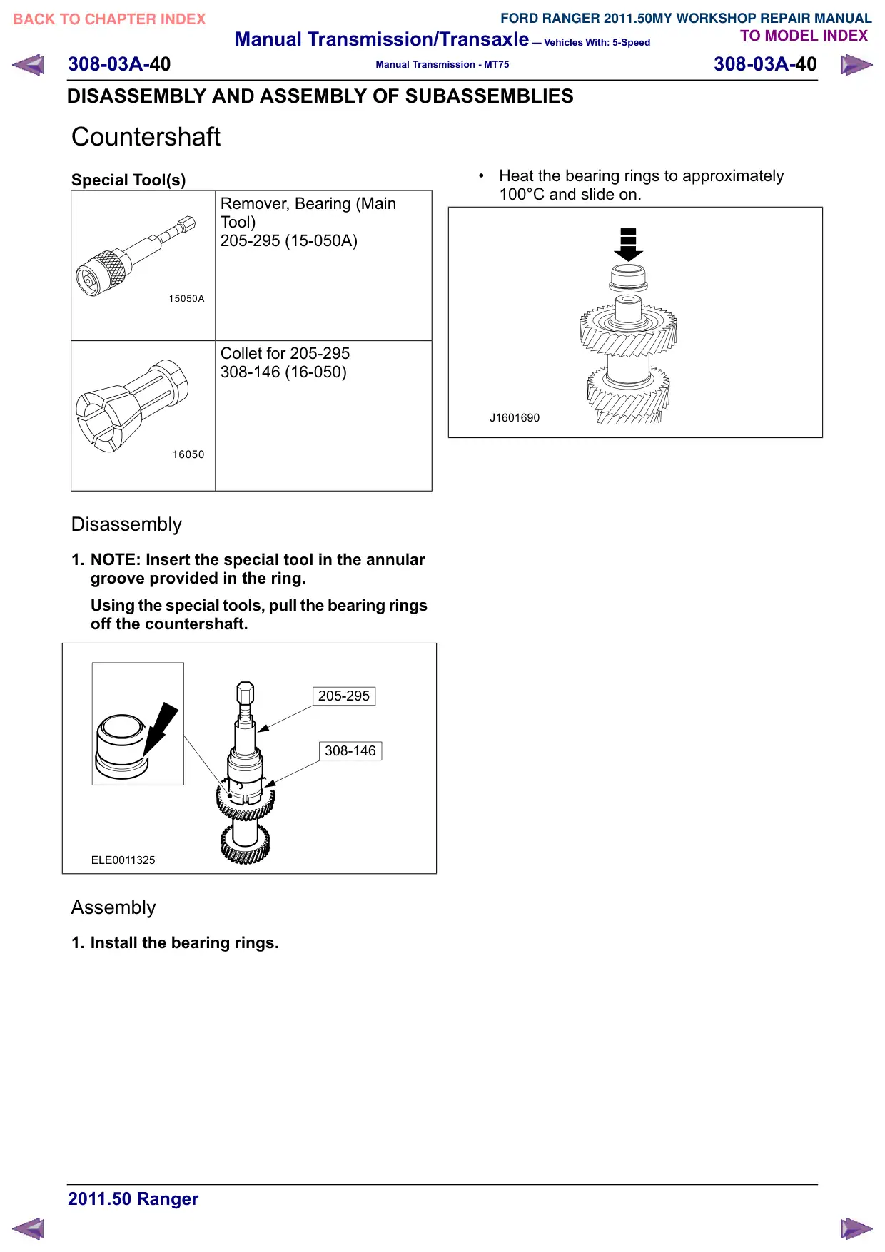
1. NOTE: Insert the special tool in the annular
groove provided in the ring.
Using the special tools, pull the bearing rings
off the countershaft.
205-295
308-146
ELE0011325
Assembly
1. Install the bearing rings.
Heat the bearing rings to approximately
100°C and slide on.
J1601690
Manual Transmission/Transaxle – Vehicles With: 5-Speed
308-03A-41
308-03A-41
Manual Transmission - MT75
DISASSEMBLY AND ASSEMBLY OF SUBASSEMBLIES
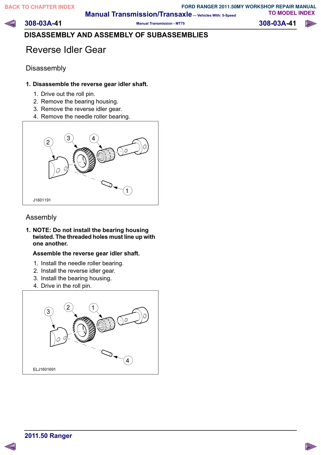
Reverse Idler Gear
Disassembly
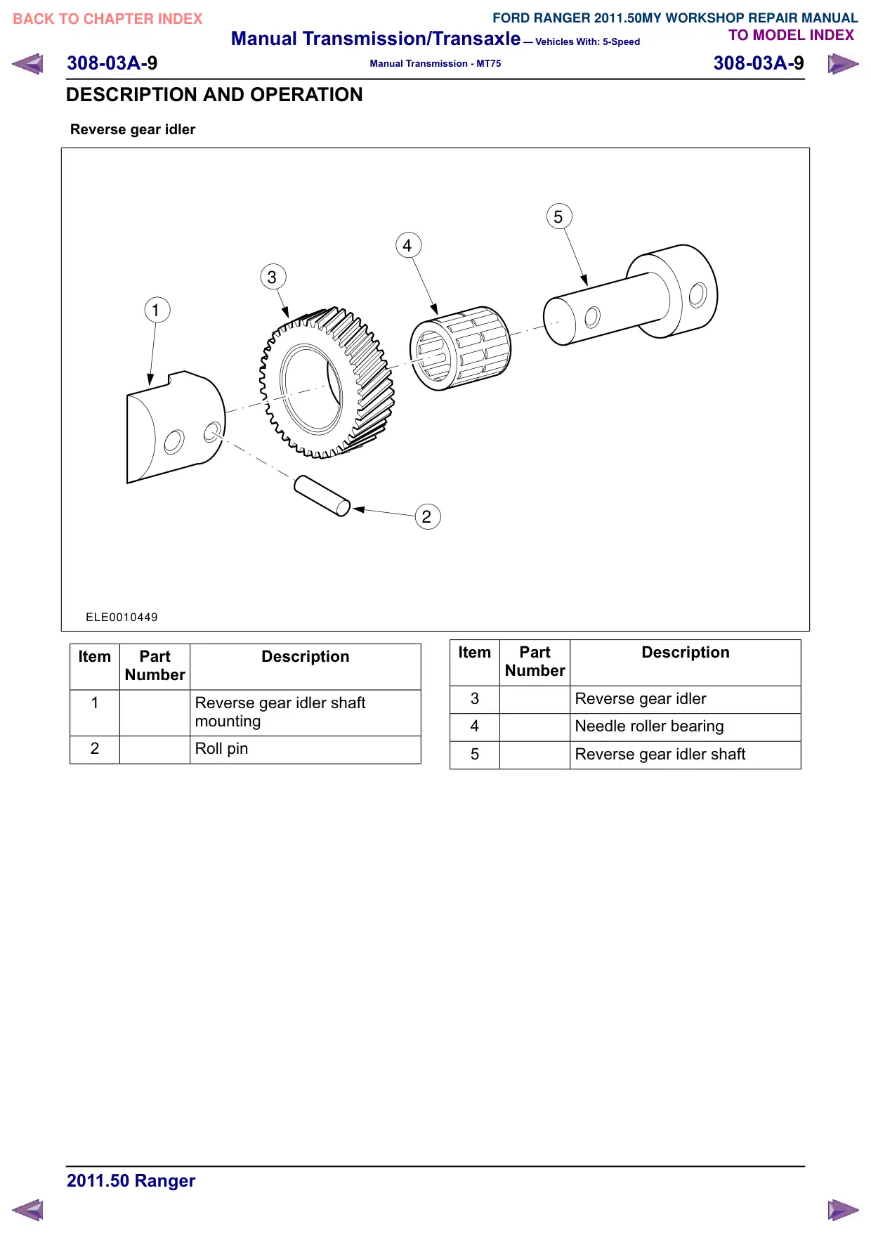
1. Disassemble the reverse gear idler shaft.
1. Drive out the roll pin.
2. Remove the bearing housing.
3. Remove the reverse idler gear.
4. Remove the needle roller bearing.
3
4
2
1
J1601191
Assembly
1. NOTE: Do not install the bearing housing
twisted. The threaded holes must line up with
one another.
Assemble the reverse gear idler shaft.
1. Install the needle roller bearing.
2. Install the reverse idler gear.
3. Install the bearing housing.
4. Drive in the roll pin.
2
1
3
4
ELJ1601691
Manual Transmission/Transaxle – Vehicles With: 5-Speed
308-03A-42
308-03A-42
Manual Transmission - MT75
DISASSEMBLY AND ASSEMBLY OF SUBASSEMBLIES
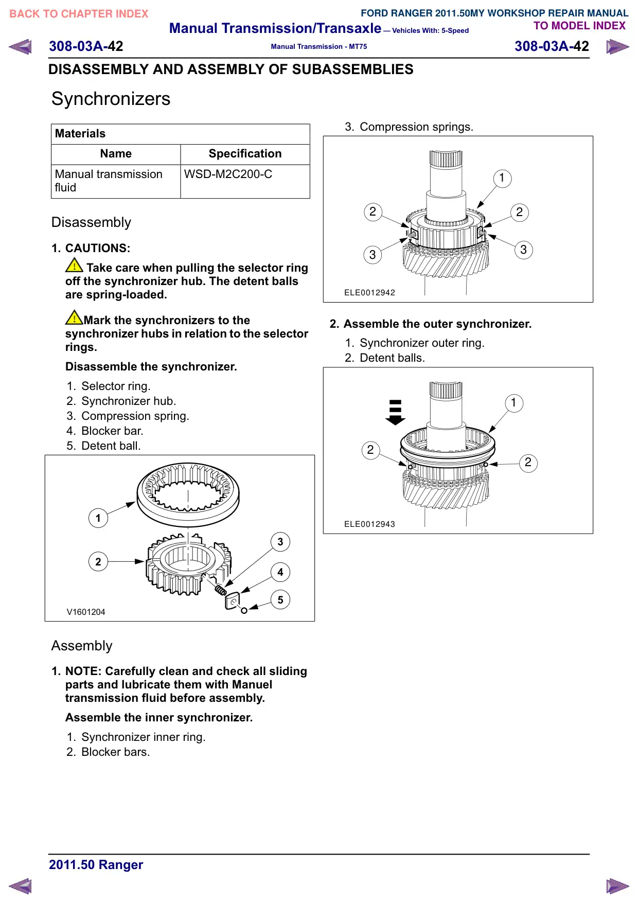
Synchronizers
Materials
Name
Specification
Manual transmission
WSD-M2C200-C
fluid
Disassembly
1. CAUTIONS:
Take care when pulling the selector ring
off the synchronizer hub. The detent balls
are spring-loaded.
Mark the synchronizers to the
synchronizer hubs in relation to the selector
rings.
Disassemble the synchronizer.
1. Selector ring.
2. Synchronizer hub.
3. Compression spring.
4. Blocker bar.
5. Detent ball.
1
3
2
4
5
V1601204
Assembly
1. NOTE: Carefully clean and check all sliding
parts and lubricate them with Manuel
transmission fluid before assembly.
Assemble the inner synchronizer.
1. Synchronizer inner ring.
2. Blocker bars.
3. Compression springs.
1
2
2
3
3
ELE0012942
2. Assemble the outer synchronizer.
1. Synchronizer outer ring.
2. Detent balls.
1
2
2
ELE0012943
Manual Transmission/Transaxle – Vehicles With: 5-Speed
308-03A-43
308-03A-43
Manual Transmission - MT75
DISASSEMBLY AND ASSEMBLY OF SUBASSEMBLIES
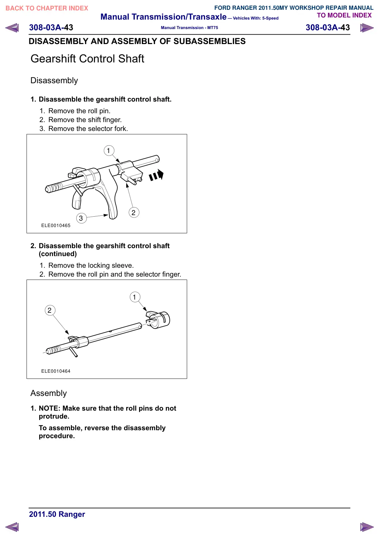
Gearshift Control Shaft
Disassembly
1. Disassemble the gearshift control shaft.
1. Remove the roll pin.
2. Remove the shift finger.
3. Remove the selector fork.
1
2
3
ELE0010465
2. Disassemble the gearshift control shaft
(continued)
1. Remove the locking sleeve.
2. Remove the roll pin and the selector finger.
1
2
ELE0010464
Assembly
1. NOTE: Make sure that the roll pins do not
protrude.
To assemble, reverse the disassembly
procedure.
Manual Transmission/Transaxle – Vehicles With: 5-Speed
308-03A-45
308-03A-45
Manual Transmission - MT75
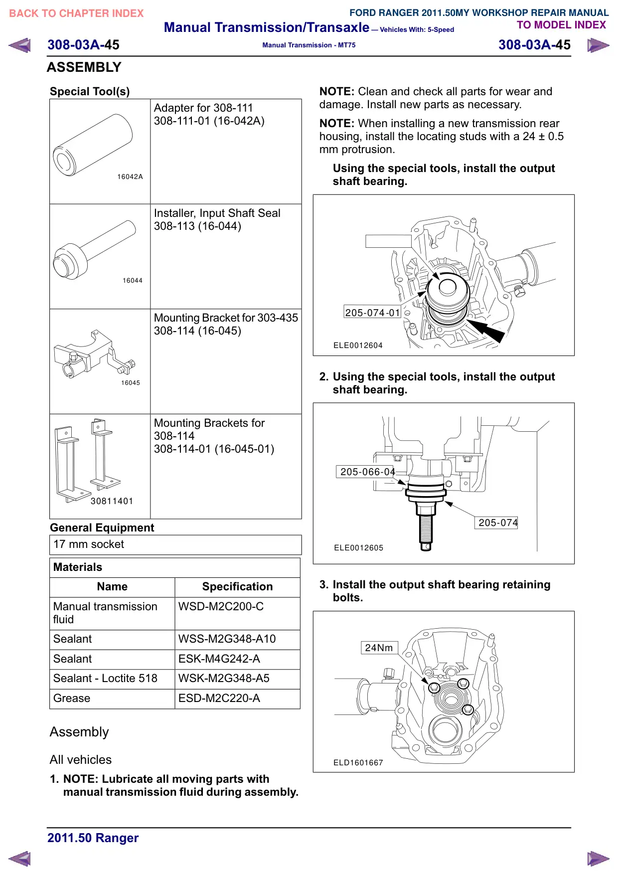
ASSEMBLY
Special Tool(s)
Adapter for 308-111
308-111-01 (16-042A)
16042A
Installer, Input Shaft Seal
308-113 (16-044)
16044
Mounting Bracket for 303-435
308-114 (16-045)
16045
Mounting Brackets for
308-114
308-114-01 (16-045-01)
30811401
General Equipment
17 mm socket
Materials
Name
Specification
Manual transmission
WSD-M2C200-C
fluid
Sealant
WSS-M2G348-A10
Sealant
ESK-M4G242-A
Sealant - Loctite 518
WSK-M2G348-A5
Grease
ESD-M2C220-A
Assembly
All vehicles
1. NOTE: Lubricate all moving parts with
manual transmission fluid during assembly.
NOTE: Clean and check all parts for wear and
damage. Install new parts as necessary.
NOTE: When installing a new transmission rear
housing, install the locating studs with a 24 ± 0.5
mm protrusion.
Using the special tools, install the output
shaft bearing.
205-074-01
ELE0012604
2. Using the special tools, install the output
shaft bearing.
205-066-04
205-074
ELE0012605
3. Install the output shaft bearing retaining
bolts.
24Nm
ELD1601667
Manual Transmission/Transaxle – Vehicles With: 5-Speed
308-03A-46
308-03A-46
Manual Transmission - MT75
ASSEMBLY
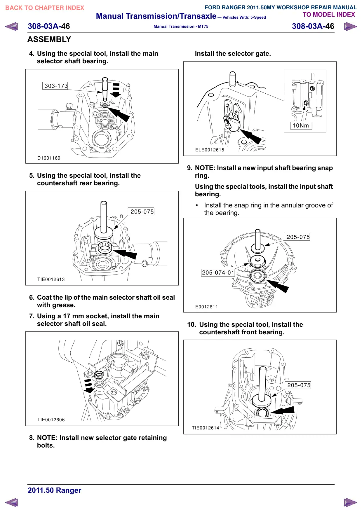
4. Using the special tool, install the main
selector shaft bearing.
303-173
D1601169
5. Using the special tool, install the
countershaft rear bearing.
205-075
TIE0012613
6. Coat the lip of the main selector shaft oil seal
with grease.
7. Using a 17 mm socket, install the main
selector shaft oil seal.
TIE0012606
8. NOTE: Install new selector gate retaining
bolts.
Install the selector gate.
10Nm
ELE0012615
9. NOTE: Install a new input shaft bearing snap
ring.
Using the special tools, install the input shaft
bearing.
Install the snap ring in the annular groove of
the bearing.
205-075
205-074-01
E0012611
10. Using the special tool, install the
countershaft front bearing.
205-075
TIE0012614
Manual Transmission/Transaxle – Vehicles With: 5-Speed
308-03A-47
308-03A-47
Manual Transmission - MT75
ASSEMBLY
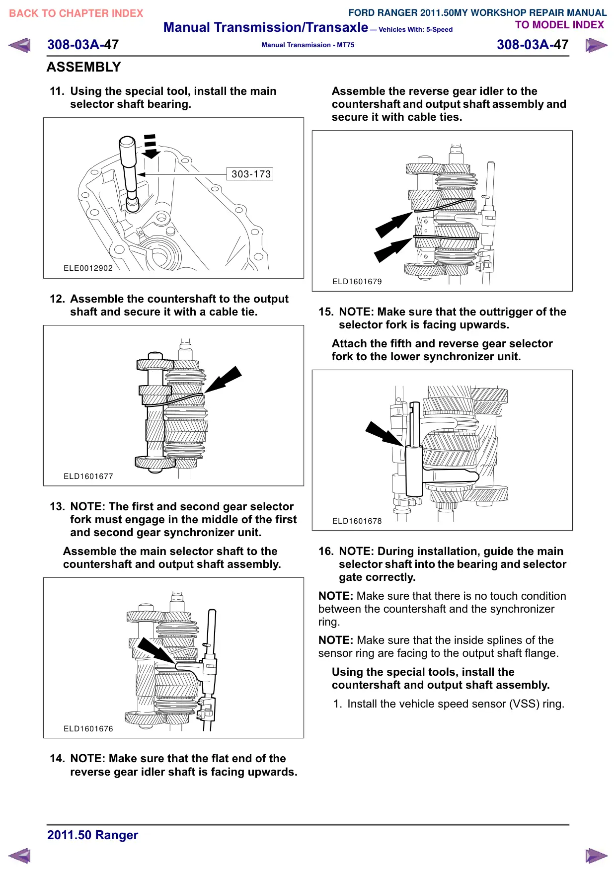
11. Using the special tool, install the main
selector shaft bearing.
303-173
ELE0012902
12. Assemble the countershaft to the output
shaft and secure it with a cable tie.
ELD1601677
13. NOTE: The first and second gear selector
fork must engage in the middle of the first
and second gear synchronizer unit.
Assemble the main selector shaft to the
countershaft and output shaft assembly.
ELD1601676
14. NOTE: Make sure that the flat end of the
reverse gear idler shaft is facing upwards.
Assemble the reverse gear idler to the
countershaft and output shaft assembly and
secure it with cable ties.
ELD1601679
15. NOTE: Make sure that the outtrigger of the
selector fork is facing upwards.
Attach the fifth and reverse gear selector
fork to the lower synchronizer unit.
ELD1601678
16. NOTE: During installation, guide the main
selector shaft into the bearing and selector
gate correctly.
NOTE: Make sure that there is no touch condition
between the countershaft and the synchronizer
ring.
NOTE: Make sure that the inside splines of the
sensor ring are facing to the output shaft flange.
Using the special tools, install the
countershaft and output shaft assembly.
1. Install the vehicle speed sensor (VSS) ring.
Manual Transmission/Transaxle – Vehicles With: 5-Speed
308-03A-48
308-03A-48
Manual Transmission - MT75
ASSEMBLY
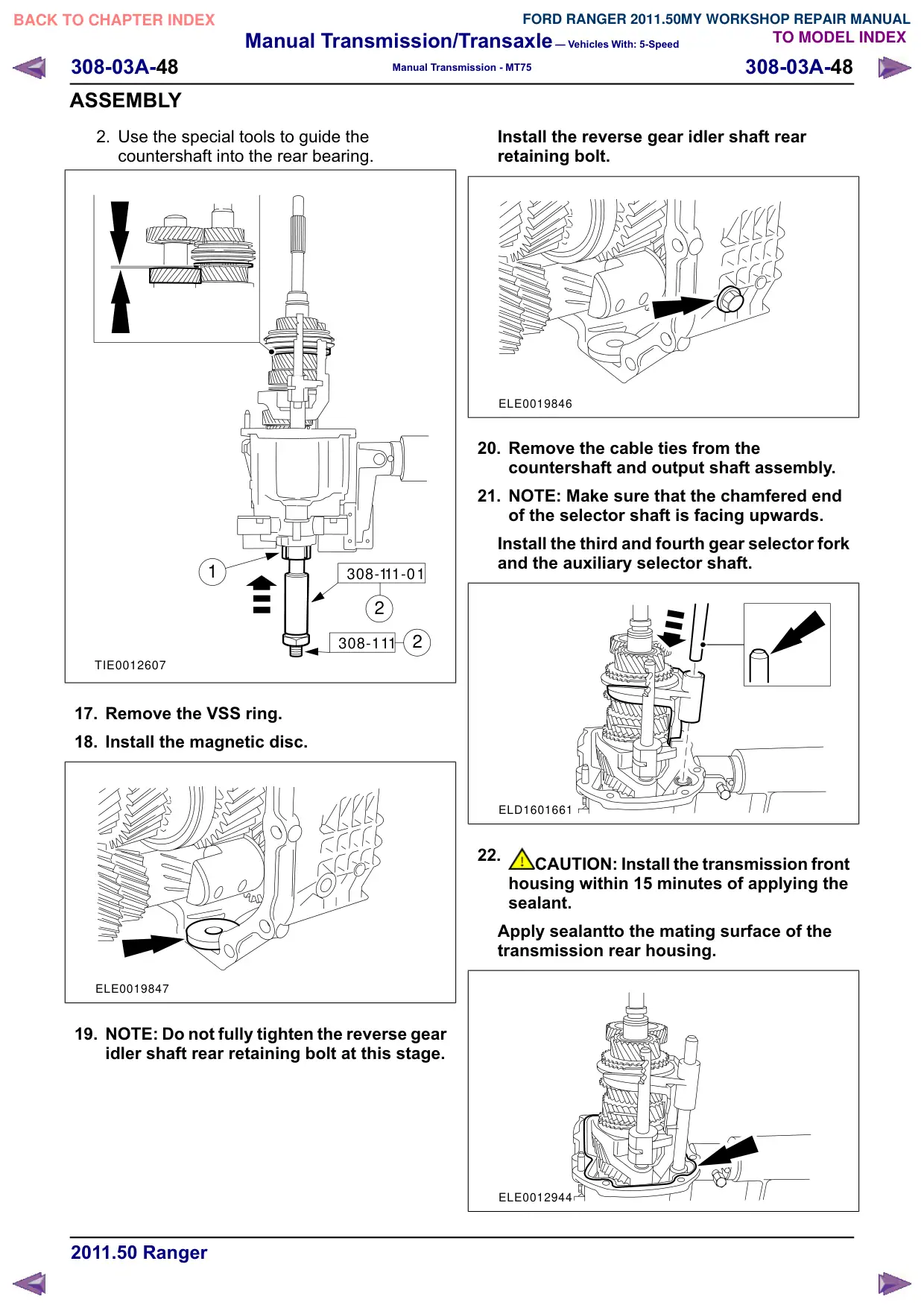
2. Use the special tools to guide the
countershaft into the rear bearing.
1
308-111-01
2
2
308-111
TIE0012607
17. Remove the VSS ring.
18. Install the magnetic disc.
ELE0019847
19. NOTE: Do not fully tighten the reverse gear
idler shaft rear retaining bolt at this stage.
Install the reverse gear idler shaft rear
retaining bolt.
ELE0019846
20. Remove the cable ties from the
countershaft and output shaft assembly.
21. NOTE: Make sure that the chamfered end
of the selector shaft is facing upwards.
Install the third and fourth gear selector fork
and the auxiliary selector shaft.
ELD1601661
22.
CAUTION: Install the transmission front
housing within 15 minutes of applying the
sealant.
Apply sealantto the mating surface of the
transmission rear housing.
ELE0012944
Manual Transmission/Transaxle – Vehicles With: 5-Speed
308-03A-49
308-03A-49
Manual Transmission - MT75
ASSEMBLY
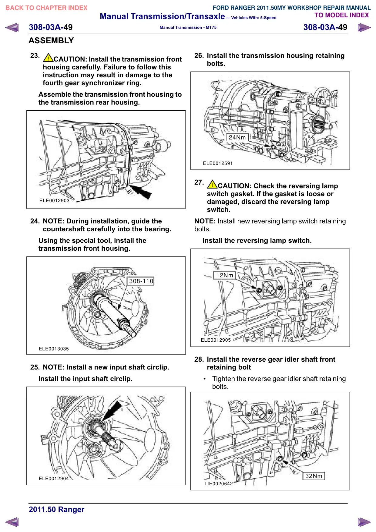
23.
CAUTION: Install the transmission front
housing carefully. Failure to follow this
instruction may result in damage to the
fourth gear synchronizer ring.
Assemble the transmission front housing to
the transmission rear housing.
ELE0012903
24. NOTE: During installation, guide the
countershaft carefully into the bearing.
Using the special tool, install the
transmission front housing.
308-110
ELE0013035
25. NOTE: Install a new input shaft circlip.
Install the input shaft circlip.
ELE0012904
26. Install the transmission housing retaining
bolts.
24Nm
ELE0012591
27.
CAUTION: Check the reversing lamp
switch gasket. If the gasket is loose or
damaged, discard the reversing lamp
switch.
NOTE: Install new reversing lamp switch retaining
bolts.
Install the reversing lamp switch.
12Nm
ELE0012905
28. Install the reverse gear idler shaft front
retaining bolt
Tighten the reverse gear idler shaft retaining
bolts.
32Nm
TIE0020642
Manual Transmission/Transaxle – Vehicles With: 5-Speed
308-03A-50
308-03A-50
Manual Transmission - MT75
ASSEMBLY
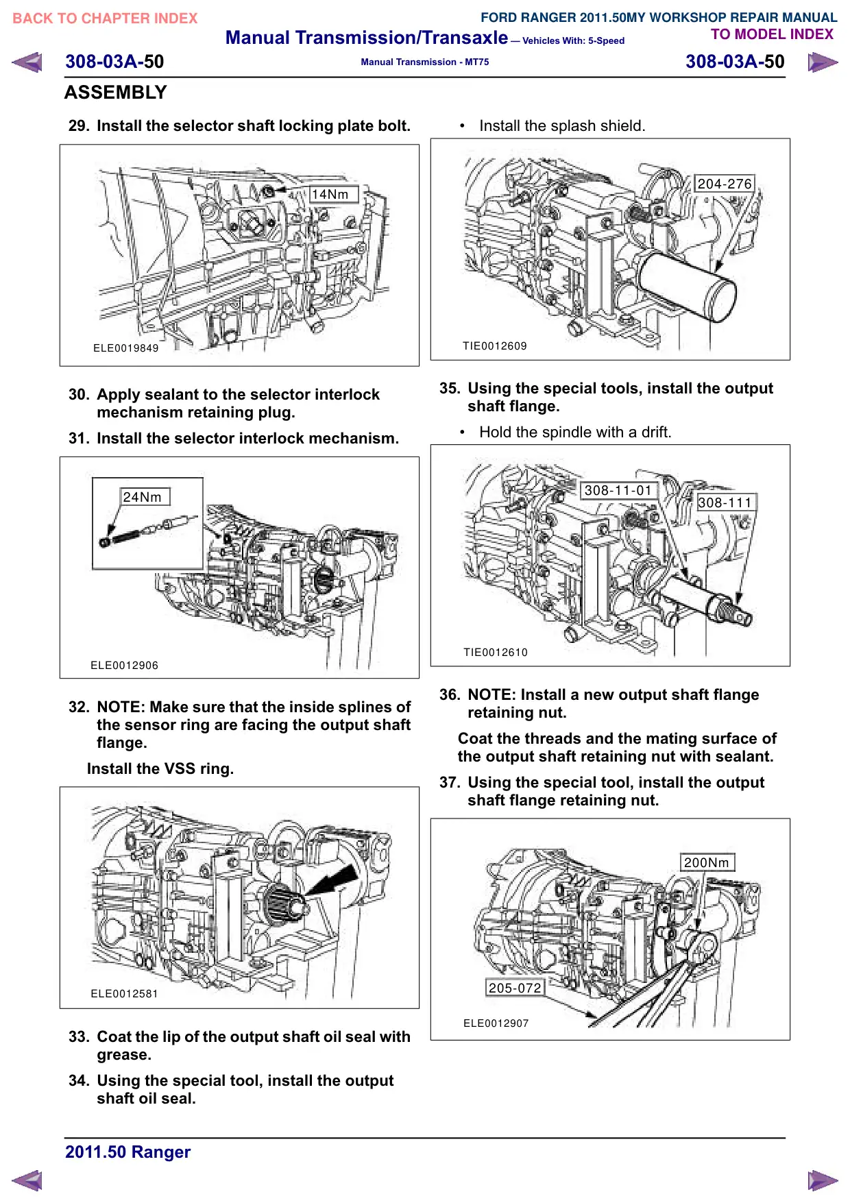
29. Install the selector shaft locking plate bolt.
14Nm
ELE0019849
30. Apply sealant to the selector interlock
mechanism retaining plug.
31. Install the selector interlock mechanism.
24Nm
ELE0012906
32. NOTE: Make sure that the inside splines of
the sensor ring are facing the output shaft
flange.
Install the VSS ring.
ELE0012581
33. Coat the lip of the output shaft oil seal with
grease.
34. Using the special tool, install the output
shaft oil seal.
Install the splash shield.
204-276
TIE0012609
35. Using the special tools, install the output
shaft flange.
Hold the spindle with a drift.
308-11-01
308-111
TIE0012610
36. NOTE: Install a new output shaft flange
retaining nut.
Coat the threads and the mating surface of
the output shaft retaining nut with sealant.
37. Using the special tool, install the output
shaft flange retaining nut.
200Nm
205-072
ELE0012907
Manual Transmission/Transaxle – Vehicles With: 5-Speed
308-03A-51
308-03A-51
Manual Transmission - MT75
ASSEMBLY
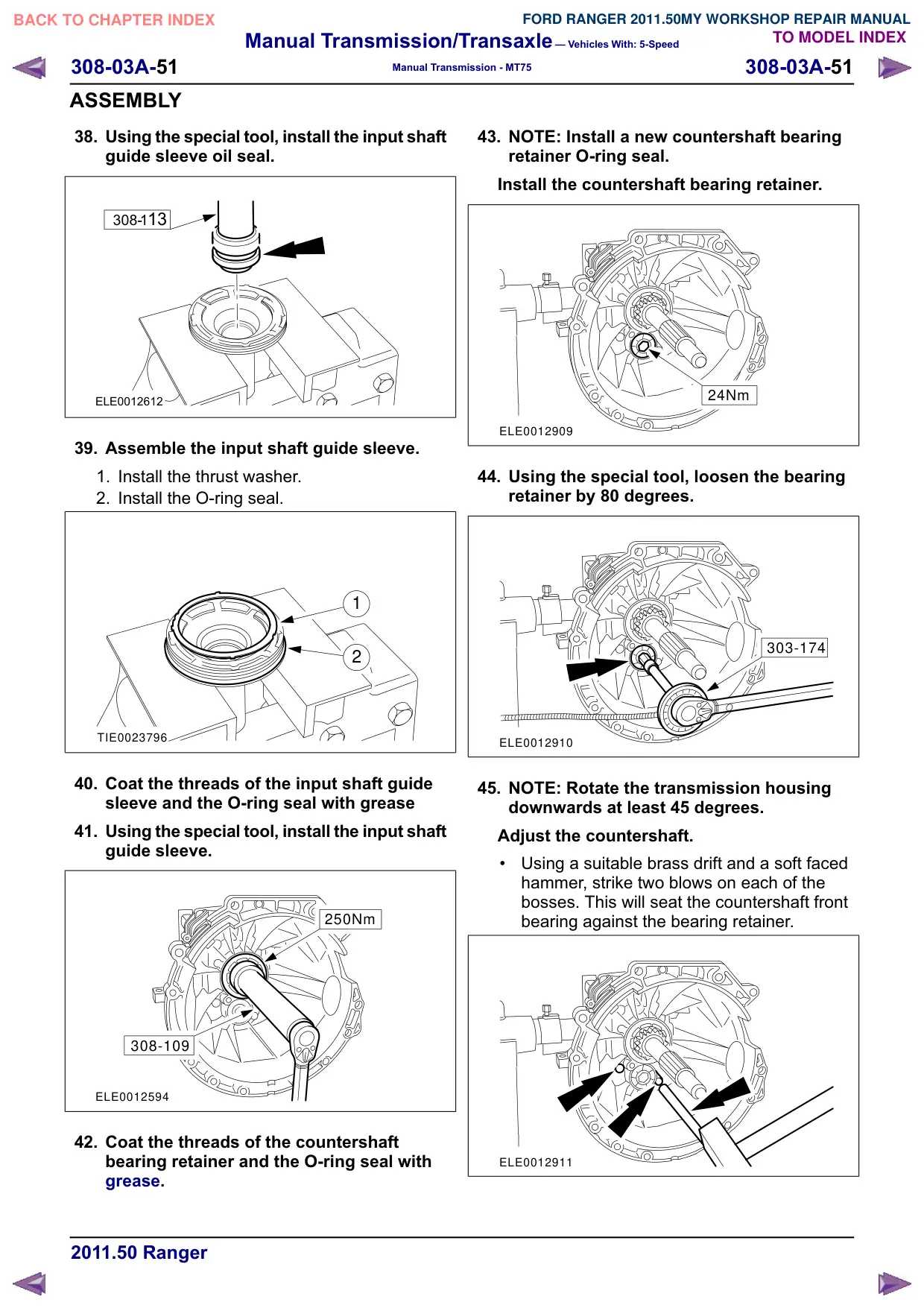
38. Using the special tool, install the input shaft
guide sleeve oil seal.
308-113
ELE0012612
39. Assemble the input shaft guide sleeve.
1. Install the thrust washer.
2. Install the O-ring seal.
1
2
TIE0023796
40. Coat the threads of the input shaft guide
sleeve and the O-ring seal with grease
41. Using the special tool, install the input shaft
guide sleeve.
250Nm
308-109
ELE0012594
42. Coat the threads of the countershaft
bearing retainer and the O-ring seal with
grease.
43. NOTE: Install a new countershaft bearing
retainer O-ring seal.
Install the countershaft bearing retainer.
24Nm
ELE0012909
44. Using the special tool, loosen the bearing
retainer by 80 degrees.
303-174
ELE0012910
45. NOTE: Rotate the transmission housing
downwards at least 45 degrees.
Adjust the countershaft.
Using a suitable brass drift and a soft faced
hammer, strike two blows on each of the
bosses. This will seat the countershaft front
bearing against the bearing retainer.
ELE0012911
Manual Transmission/Transaxle – Vehicles With: 5-Speed
308-03A-52
308-03A-52
Manual Transmission - MT75
ASSEMBLY
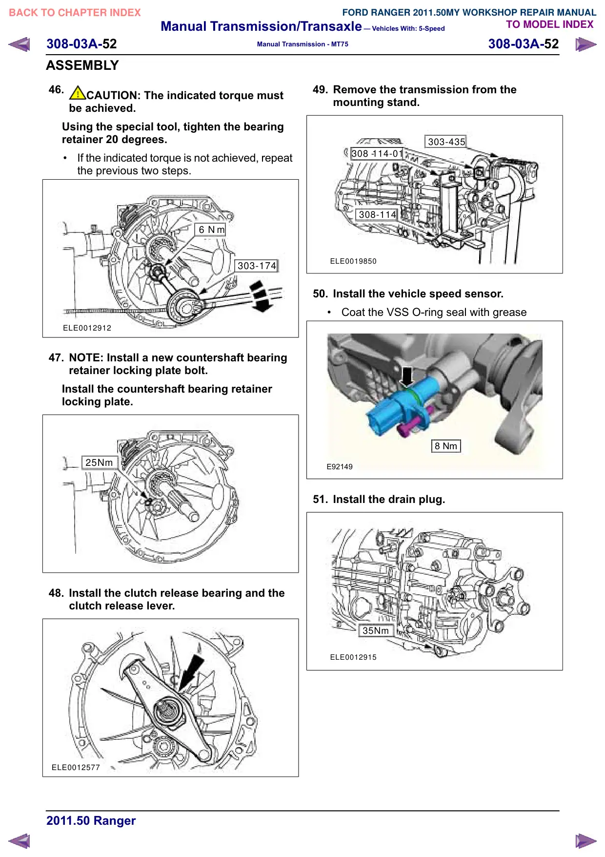
46.
CAUTION: The indicated torque must
be achieved.
Using the special tool, tighten the bearing
retainer 20 degrees.
If the indicated torque is not achieved, repeat
the previous two steps.
6 N m
303-174
ELE0012912
47. NOTE: Install a new countershaft bearing
retainer locking plate bolt.
Install the countershaft bearing retainer
locking plate.
25Nm
48. Install the clutch release bearing and the
clutch release lever.
ELE0012577
49. Remove the transmission from the
mounting stand.
303-435
308 -114-01
308-114
ELE0019850
50. Install the vehicle speed sensor.
Coat the VSS O-ring seal with grease
8 Nm
E92149
51. Install the drain plug.
35Nm
ELE0012915
Manual Transmission/Transaxle – Vehicles With: 5-Speed
308-03A-53
308-03A-53
Manual Transmission - MT75
ASSEMBLY
Vehicles with tachograph
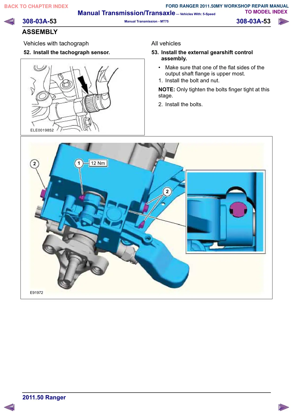
52. Install the tachograph sensor.
ELE0019852
2
1
12 Nm
E91972
All vehicles
53. Install the external gearshift control
assembly.
Make sure that one of the flat sides of the
output shaft flange is upper most.
1. Install the bolt and nut.
NOTE: Only tighten the bolts finger tight at this
stage.
2. Install the bolts.
2
Manual Transmission/Transaxle – Vehicles With: 5-Speed
308-03A-54
308-03A-54
Manual Transmission - MT75
ASSEMBLY
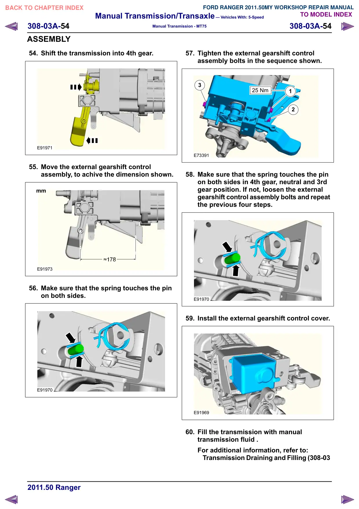
54. Shift the transmission into 4th gear.
E91971
55. Move the external gearshift control
assembly, to achive the dimension shown.
mm
mm
E91973
56. Make sure that the spring touches the pin
on both sides.
E91970
57. Tighten the external gearshift control
assembly bolts in the sequence shown.
3
25 Nm
25 Nm
1
2
E73391
58. Make sure that the spring touches the pin
on both sides in 4th gear, neutral and 3rd
gear position. If not, loosen the external
gearshift control assembly bolts and repeat
the previous four steps.
E91970
59. Install the external gearshift control cover.
E91969
60. Fill the transmission with manual
transmission fluid .
For additional information, refer to:
Transmission Draining and Filling (308-03
Manual Transmission/Transaxle – Vehicles With: 5-Speed
308-03A-56
308-03A-56
Manual Transmission - MT75
INSTALLATION
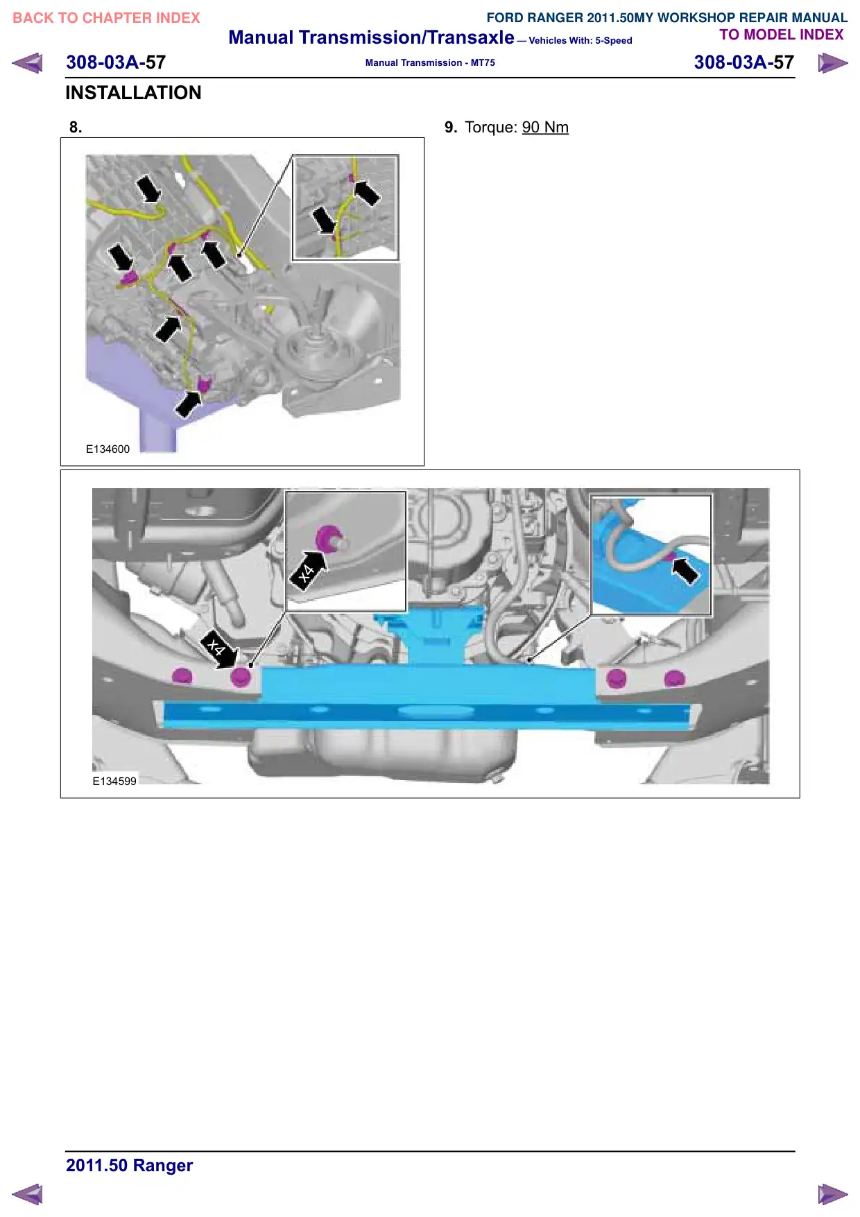
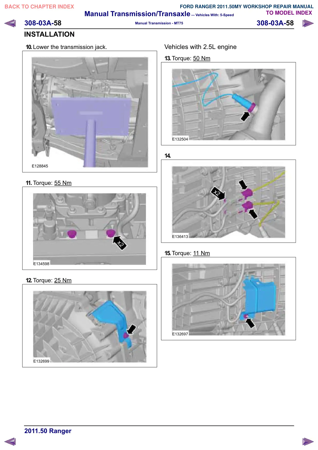
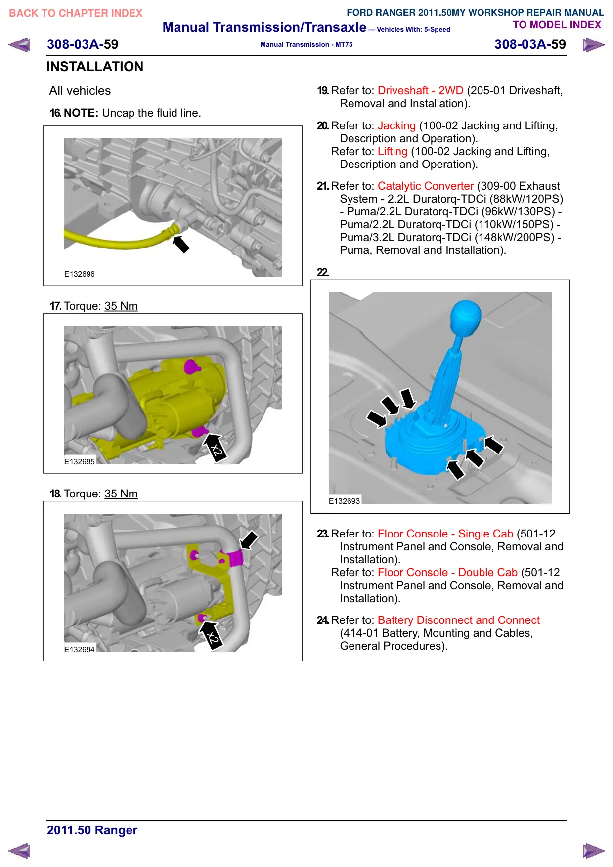
Transmission – 2WD
Installation
General Equipment
Transmission Jack
1. Check the pilot bearing for damage. If damaged,
install a new pilot bearing.
Refer to: Pilot Bearing - 2.5L Duratec-HE
(122kW/165PS) - MI4 (308-01 Clutch -
Vehicles With: 5-Speed Manual Transmission
- MT75, Removal and Installation).
2. NOTE: Do not apply grease to a newly installed
pilot bearing.
Apply approximately one gram of grease to the
pilot bearing.
3. Apply a thin film of grease to the input shaft
guide sleeve.
4. Shift the transmission into third gear.
All vehicles
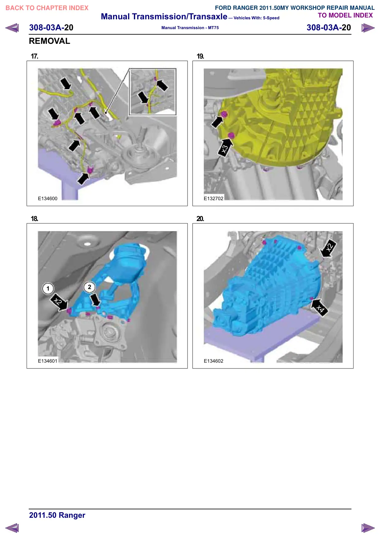
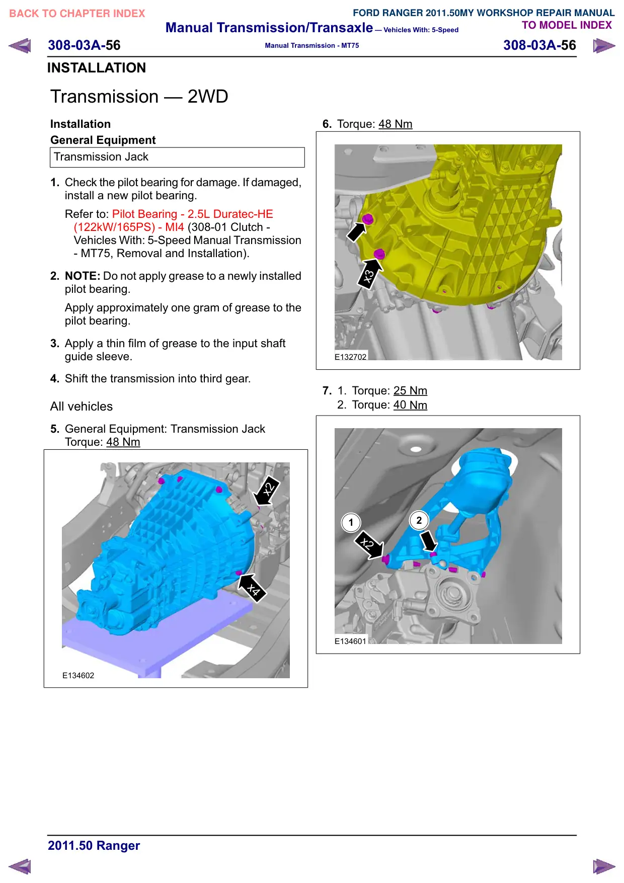
5. General Equipment: Transmission Jack
Torque: 48 Nm
x2
x2
x4
x4
E134602
6. Torque: 48 Nm
x3
x3
E132702
7.
1.
Torque: 25 Nm
2. Torque: 40 Nm
2
1
x2
x2
E134601
Manual Transmission/Transaxle – Vehicles With: 5-Speed
308-03A-60
308-03A-60
Manual Transmission - MT75
INSTALLATION
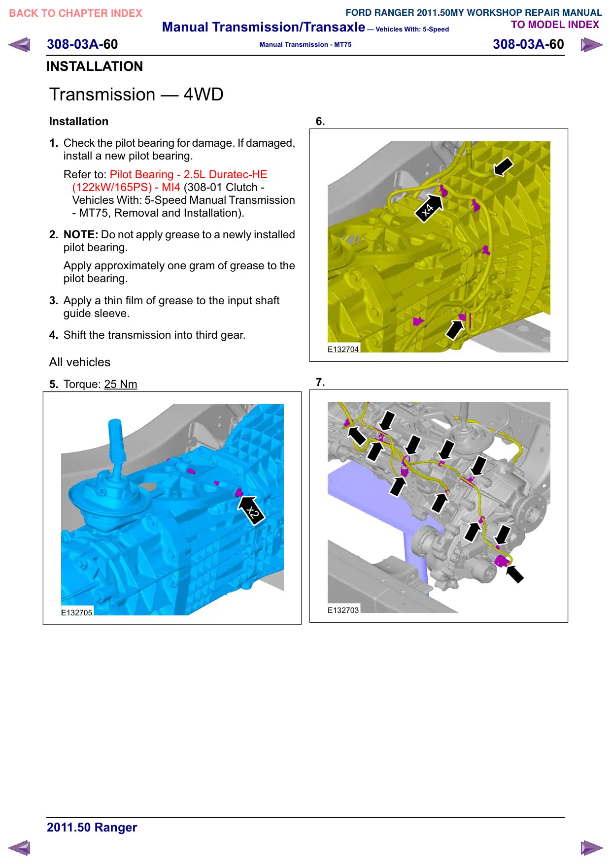
Transmission – 4WD
Installation
1. Check the pilot bearing for damage. If damaged,
install a new pilot bearing.
Refer to: Pilot Bearing - 2.5L Duratec-HE
(122kW/165PS) - MI4 (308-01 Clutch -
Vehicles With: 5-Speed Manual Transmission
- MT75, Removal and Installation).
2. NOTE: Do not apply grease to a newly installed
pilot bearing.
Apply approximately one gram of grease to the
pilot bearing.
3. Apply a thin film of grease to the input shaft
guide sleeve.
4. Shift the transmission into third gear.
All vehicles
5. Torque: 25 Nm
x2
x2
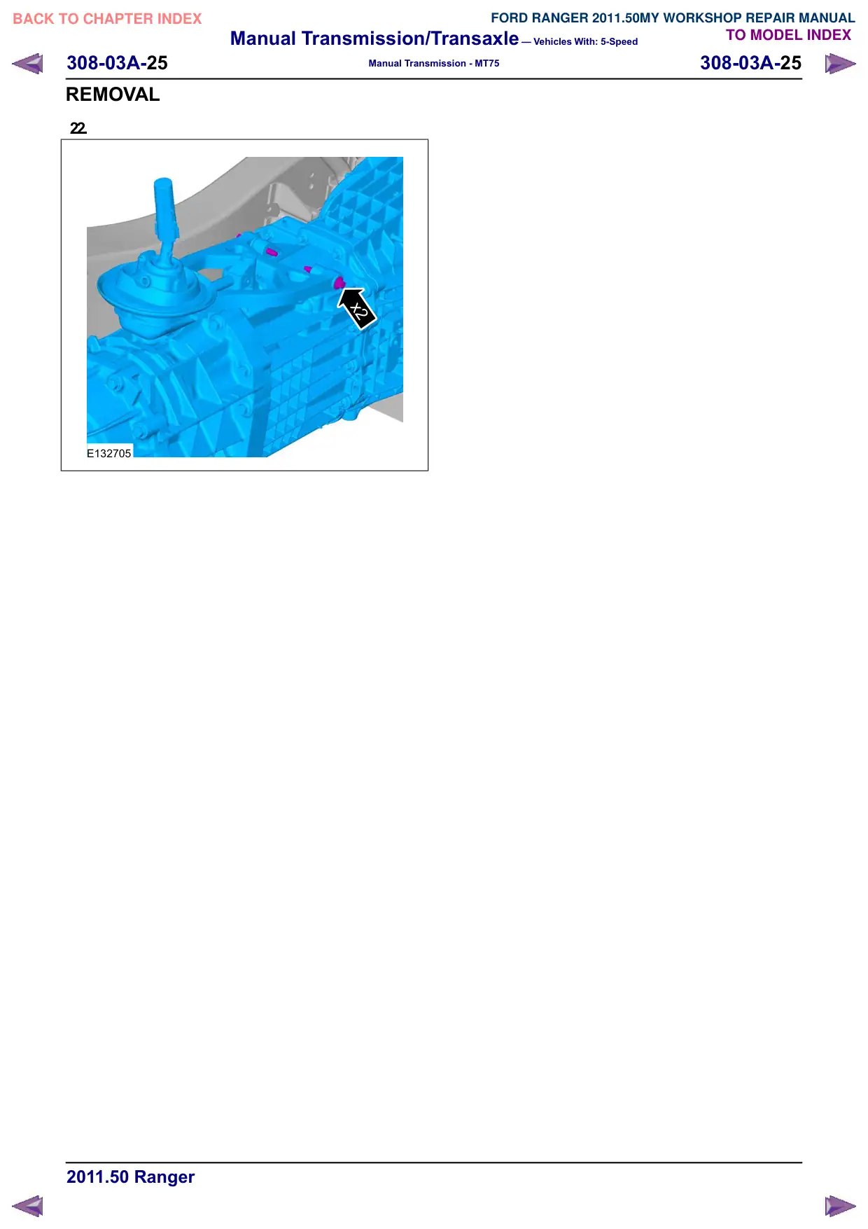
E132705
6.
x4
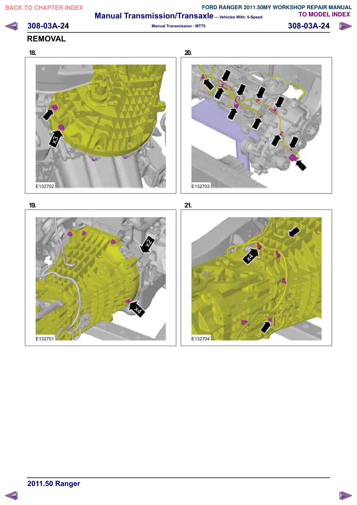
E132704
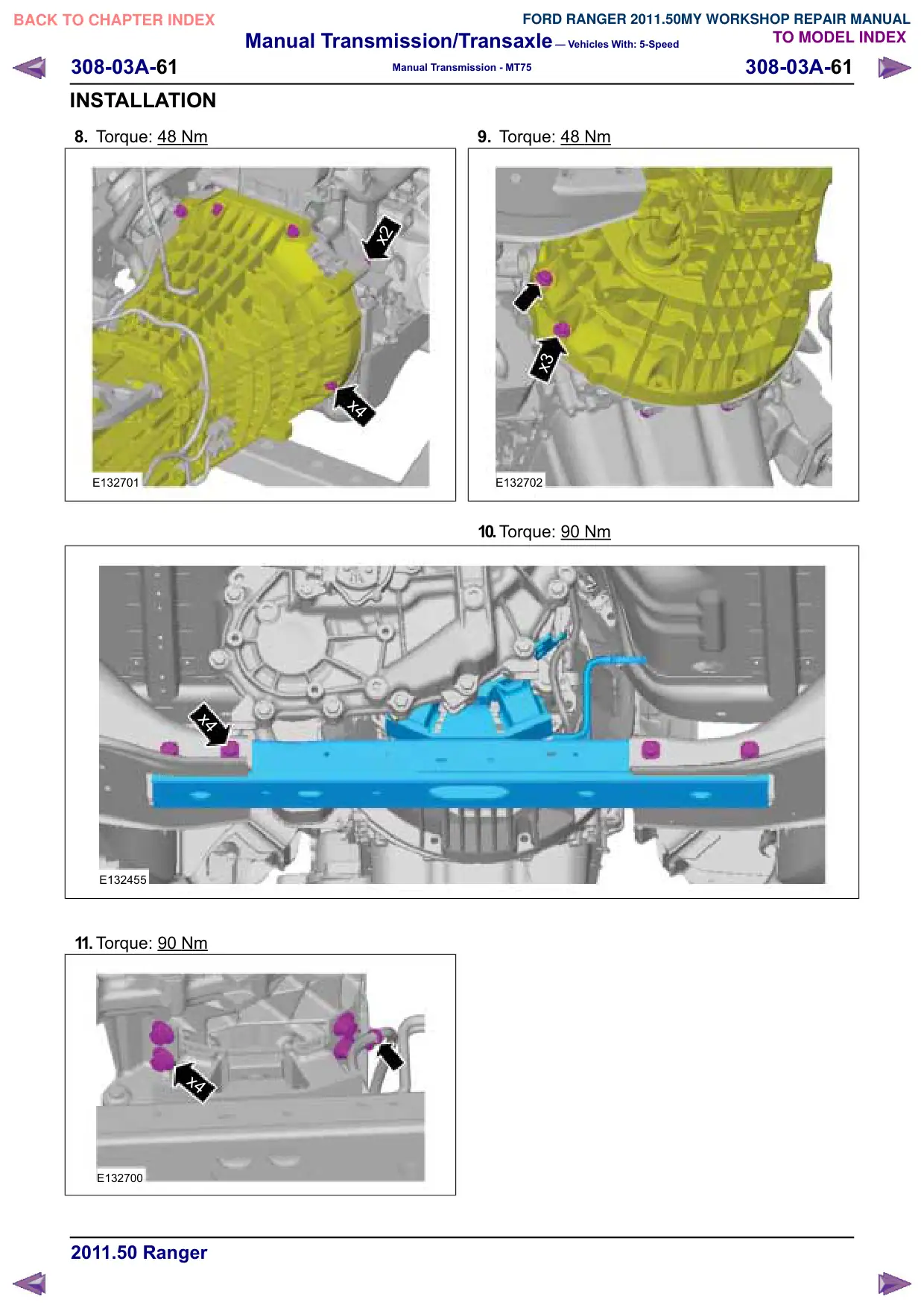
7.
E132703