Automatic Transmission/Transaxle – Vehicles With:
307-01-4
307-01-4
6-Speed Automatic Transaxle - 6R80
DESCRIPTION AND OPERATION
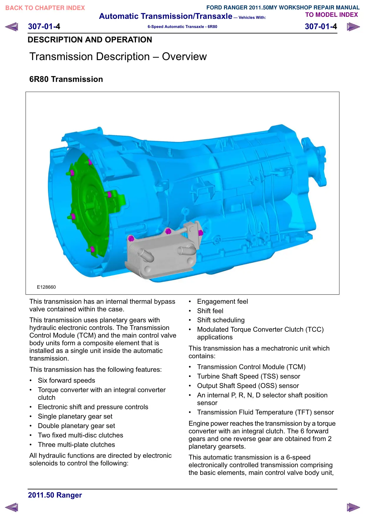
Transmission Description œ Overview
6R80 Transmission
E128660
This transmission has an internal thermal bypass
valve contained within the case.
This transmission uses planetary gears with
hydraulic electronic controls. The Transmission
Control Module (TCM) and the main control valve
body units form a composite element that is
installed as a single unit inside the automatic
transmission.
This transmission has the following features:
Six forward speeds
Torque converter with an integral converter
clutch
Electronic shift and pressure controls
Single planetary gear set
Double planetary gear set
Two fixed multi-disc clutches
Three multi-plate clutches
All hydraulic functions are directed by electronic
solenoids to control the following:
Engagement feel
Shift feel
Shift scheduling
Modulated Torque Converter Clutch (TCC)
applications
This transmission has a mechatronic unit which
contains:
Transmission Control Module (TCM)
Turbine Shaft Speed (TSS) sensor
Output Shaft Speed (OSS) sensor
An internal P, R, N, D selector shaft position
sensor
Transmission Fluid Temperature (TFT) sensor
Engine power reaches the transmission by a torque
converter with an integral clutch. The 6 forward
gears and one reverse gear are obtained from 2
planetary gearsets.
This automatic transmission is a 6-speed
HOHFWURQLFDOO\ FRQWUROOHG WUDQVPLVVLRQ FRPSULVLQJ
the basic elements, main control valve body unit,
Automatic Transmission/Transaxle – Vehicles With:
307-01-5
307-01-5
6-Speed Automatic Transaxle - 6R80
DESCRIPTION AND OPERATION
torque converter, 1 solenoid valve and 6 pressure
regulators. Gear selection is achieved by the
control of automatic transmission fluid flow to
operate various internal clutches. The TCM
operates the electrical components and provides
for the control of gear selection shift pressure,
which increases refinement and torque converter
slip.
In the event of a system fault, the TCM also
provides for Failure Mode Effect Management to
maintain maximum functional operation of the
transmission with a minimum reduction in driver,
passenger or vehicle safety. In the event of a total
loss of control or electrical power, the basic
transmission functions P, R, N and D are retained.
Also 3rd or 5th gear is retained by the hydraulic
system. The gear retained is dependent upon the
gear selected at the time of the failure.
Major Components
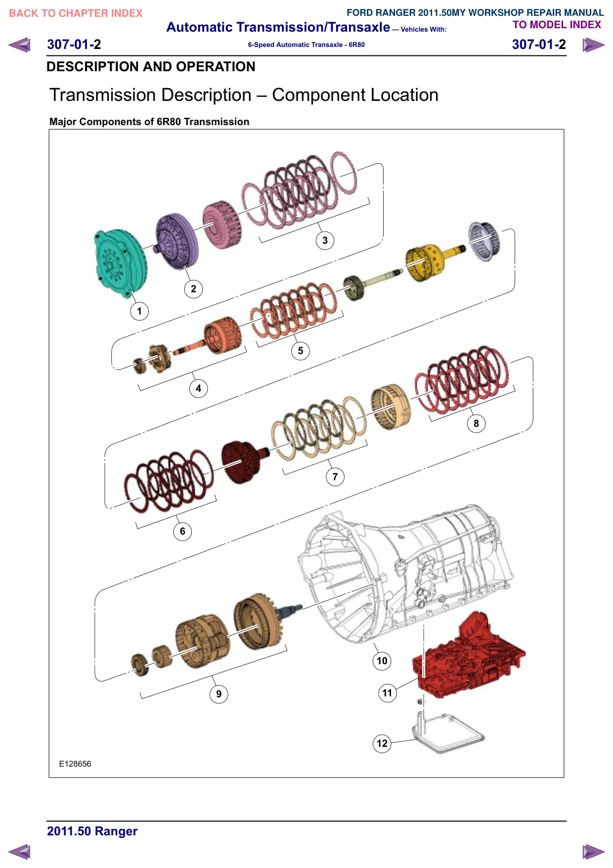
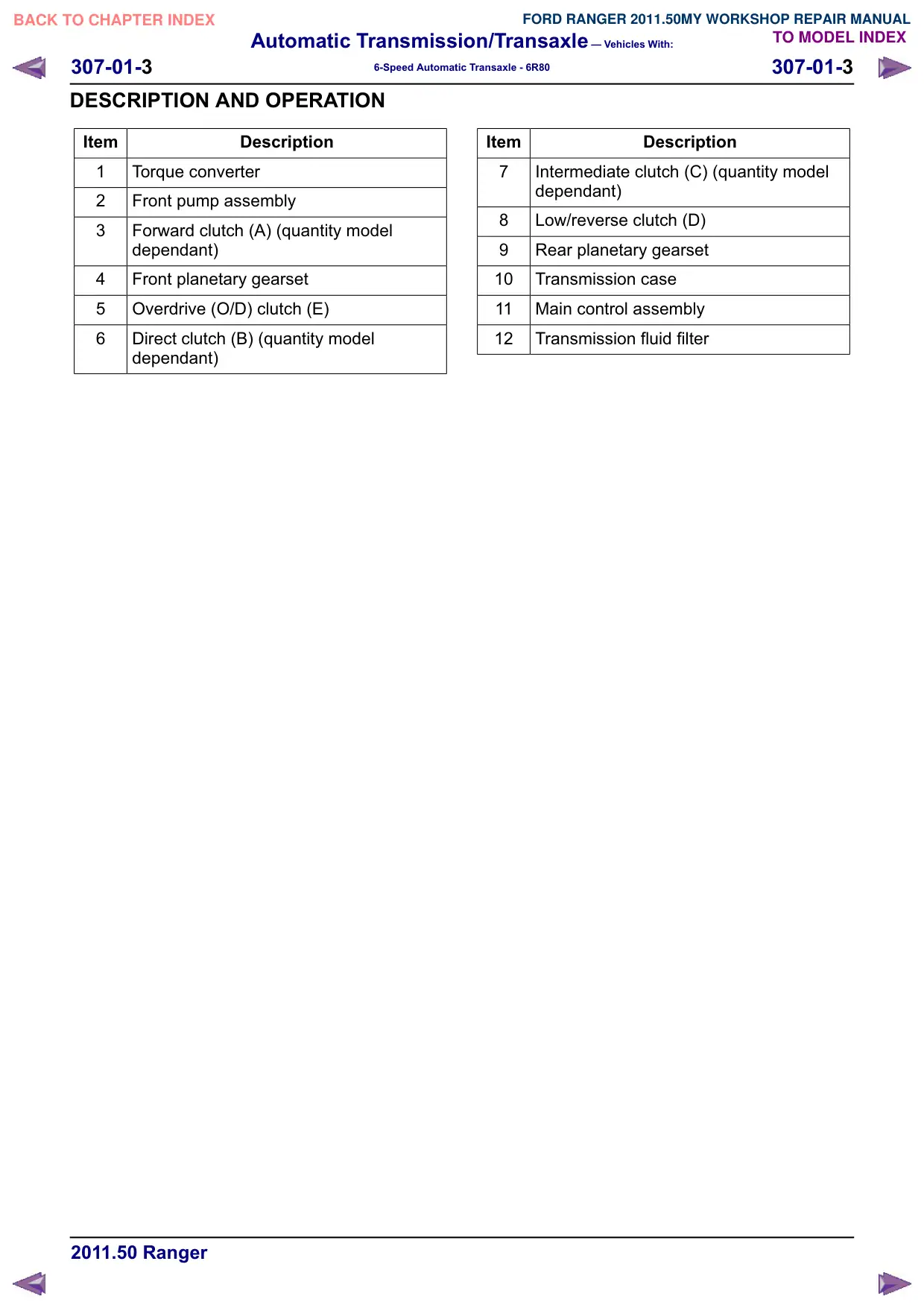
This transmission has the following major
components:
Transmission case with integral torque converter
housing and extension housing
Torque converter
Fluid pump
Three drive clutches:
œ Forward clutch (A)
œ Direct clutch (B)
œ Overdrive (O/D) clutch (E)
Two brake clutches:
œ Intermediate clutch (C)
œ Low/reverse clutch (D)
Two planetary gearsets:
œ Front single planetary gearset (1 sun gear,
1 carrier, 1 ring gear)
œ Rear Ravigenaux planetary gearset (2 sun
gears, 1 carrier with 2 sets of pinion gears
and 1 ring gear)
Main control (mechatronic assembly):
œ Upper valve body
œ Lower valve body
œ Transmission Control Module (TCM)
œ Transmission Range (TR) sensor
œ Turbine Shaft Speed (TSS) sensor
œ Output Shaft Speed (OSS) sensor
NOTE: Friction and steel plate quantity will vary
based on engine displacement. Refer to the Clutch
Plate Quantity Chart in the Specifications portion
of this section.
In addition to the torque converter, the other shift
elements are:
three rotating multi-plate clutches: forward (A),
direct (B) and overdrive (E).
two fixed multi-disc brakes: intermediate (C)
and low/reverse (D).
All gear shifts from 1st to 6th or from 6th to 1st are
power-on overlapping shifts. That is, during the
shift, one of the clutches must continue to transmit
the drive at lower main pressure until the other
clutch is able to accept the input torque.
The shift elements, clutches or brakes are engaged
hydraulically. The transmission fluid pressure builds
up between the cylinder and the piston, pressing
the clutches together.
The purpose of these shift elements is to carry out
in-load shifts with no interruption to traction.
Multi-plate clutches; forward, direct and overdrive,
supply power from the engine to the planetary
geartrain. Multi-disc brakes, intermediate and
low/reverse, press against the transmission
housing in order to achieve a torque reaction effect.
Multi-Plate Clutch
Clutches; O/D (E), forward (A) and direct (B) are
balanced in terms of dynamic pressure. That is,
their pistons are exposed to the transmission fluid
flow on both sides, in order to prevent pressure
buildup in the clutch as speed increases. This
equalization process is achieved by a baffle plate
and pressure-free transmission fluid supply by a
lubricating passage, through which the space
between piston and baffle plate is filled with
transmission fluid.
The advantages of this dynamic pressure
equalization are:
Reliable clutch engagement and release in all
speed ranges.
Improved shift refinement.
Shift Overlap Control
The electro-hydraulic shift action is obtained by
means of various valves in the TCM and main
control valve body, actuated by pressure
regulators. They engage or disengage the relevant
clutches or brakes at the correct moments.
Automatic Transmission/Transaxle – Vehicles With:
307-01-6
307-01-6
6-Speed Automatic Transaxle - 6R80
DESCRIPTION AND OPERATION
Hydraulic Systems
Fluid Pump
The torque converter is supported in the fluid pump
by a needle roller bearing. The fluid pump is driven
directly from the engine by the torque converter
shell and supplies transmission fluid to the
transmission and the hydraulic control unit.
The fluid pump draws in transmission fluid through
a transmission fluid filter and delivers it at high
pressure to the main pressure valve in the main
control valve body unit. The valve adjusts the
pressure and returns excess transmission fluid to
the transmission fluid pan.
Fluid Filter
All transmission fluid that is picked up from the
transmission fluid pan passes through the
transmission fluid filter. The transmission fluid filter
and its accompanying seal are part of the
transmission fluid path from the pan to the
transmission fluid pump.
Single Planetary Gearset
The single planetary gear O/D carrier is driven by
the input shaft. The single planetary gear set
consists of the following components:
One sun gear
Four planetary gears meshing with the sun gear
One planetary carrier
One ring gear
Ravigenaux Planetary Gearset
The Ravigenaux planetary gearset is splined to the
output shaft and consists of the following
components:
Two sun gears of different sizes
Three short planetary gear pinions meshing with
the sun gears
Three long planetary gear pinions meshing with
the sun gears
One planetary carrier
One ring gear
Output Shaft
The output shaft provides torque to the driveshaft
and rear axle assembly. It is driven by the ring gear
of the planetary gearset.
Automatic Transmission/Transaxle – Vehicles With:
307-01-7
307-01-7
6-Speed Automatic Transaxle - 6R80
GENERAL PROCEDURES
Transmission Fluid Cooler - Backflushing and Cleaning
Special Tool(s)
Transmission Heated Cooler
Line Flusher
222-00007, 222-00004
E128862
WARNING: Use transmission fluid
specified for this transmission. Do not use
any supplemental transmission fluid
additives or cleaning agents. The use of
these products could cause internal
transmission components to fail; this will
affect the operation of the transmission.
NOTE: Transmission fluid cooler backflushing and
cleaning will be performed using the Transmission
Heated Cooler Line Flusher or equivalent. Follow
the manufacturer's instructions included with the
machine. Test the equipment to make sure that a
vigorous fluid flow is present before proceeding.
NOTE: If the Transmission Heated Cooler Line
Flusher or equivalent is not available, install a new
transmission fluid cooler and/or an auxiliary
transmission fluid cooler will be required.
NOTE: If the vehicle is equipped with an in-line
transmission fluid filter, remove and discard the
in-line filter.
1. Check and top off the fluid level of the cooler
line flusher with transmission fluid.
2. Allow the transmission fluid in the cooler
line flusher 15-30 minutes to heat up to 60°C
(140°F) before using.
3. If equipped, remove and discard the in-line
transmission fluid filter.
E128858
4. Install the line adapters into the transmission
fluid cooler tubes.
5. Attach the cooler line flusher red line to the
transmission fluid cooler pressure tube quick
connect fitting.
6. Attach the cooler line flusher blue line to the
transmission fluid cooler return tube quick
connect fitting.
7. Follow the equipment instructions to purge
the transmission fluid cooler tubes and
cooler prior to starting the flushing
procedure.
8. Allow the transmission fluid cooling system
to backflush for 10-15 minutes, then flush
the transmission fluid cooler in a normal flow
direction for an additional 10-15 minutes.
Automatic Transmission/Transaxle – Vehicles With:
307-01-8
307-01-8
6-Speed Automatic Transaxle - 6R80
GENERAL PROCEDURES
Transmission Fluid Drain and Refill
Special Tool(s)
Rubber Tip Air Nozzle
100-D009 (D93L-7000-A)
ST2467-A
Fluid
Transporter/Evacuator/Injector
307-D465
ST2715-A
Adapter, Fluid Level and Fill
Plug
307-437
E129427
Vacuum Pump Kit
416-D002 (D95L-7559-A)
Integrated Diagnostic System
(IDS)
Vehicle Communication
Module, with appropriate
ST1269-A
adapters or equivalent
diagnostic tool
Materials
Name
Specification
Transmission Fluid
0(5&219
Drain
1. With the vehicle in NEUTRAL, position it on
a hoist. For additional information, refer to
Section 100-02.
2. NOTE: Some transmission fluid leakage may
occur when removing the transmission fluid
fill plug.
Remove the transmission fluid fill plug fluid
level indicator assembly located on the
passenger side front portion of the
transmission case. Removal of the
transmission fluid fill plug will relieve any
vacuum that might have built up in the
transmission. This will aid in allowing the
transmission fluid pan to be easily removed
when the bolts are removed.
E128906
3. Remove the transmission fluid pan and allow
the transmission fluid to drain.
E128907
4. NOTE: The transmission fluid pan gasket
can be reused if not damaged.
Install a new transmission fluid pan gasket,
if required.
E129417
Automatic Transmission/Transaxle – Vehicles With:
307-01-
307-01-
6-Speed Automatic Transaxle - 6R80
GENERAL PROCEDURES
5. Install the transmission fluid pan and tighten
the bolts in a crisscross pattern.
Tighten to 12NM
E128907
Refill
WARNING: The transmission fluid fill plug
is located near the exhaust system. The
exhaust will be extremely hot during this
procedure.
CAUTIONS:
This procedure contains the air purge
steps required to purge air from the
transmission fluid cooling system. This
procedure is NOT intended for use with the
Transmission Fluid Level Check.
The vehicle should not be driven if the
transmission fluid level is low as internal
failure could result.
The use of any other transmission fluid
than specified can result in the
transmission failing to operate in a normal
manner or transmission failure.
NOTE: If the transmission starts to slip, shifts
slowly or shows signs of transmission fluid leaking,
the transmission fluid level should be checked.
NOTE: Here is an overview of the Transmission
Fluid Drain and Refill procedure.
1. NOTE: The transmission will need 3.3L (3.5
qt) of transmission fluid added to the
transmission as an initial fill if: th•e
transmission has been overhauled. a• new
mechatronic assembly has been installed.
th•e transmission fluid pan or transmission
fluid filter have been removed.
Using the Transmission Fluid Fill Tube, add
3.3L (3.5 qt) of transmission fluid to the
transmission through the transmission fluid
fill hole. For additional information, refer to
Adding Additional Transmission Fluid in this
procedure.transmission fluid
2. Check the transmission fluid level cold.
The vehicle is safe to drive if the transmission
fluid is in the cold level range 32°C-43°C
(90°F-110°F).
Using the scan tool and with the engine
running, place the selector lever in each gear
position and hold approximately 5 seconds.
Place the selector lever in PARK, with the
engine at idle (600-750 rpm).
3. Separate the transmission fluid level
indicator from the transmission fluid fill plug.
E129418
4. Wipe the transmission fluid level indicator
clean. Reinstall the transmission fluid level
indicator only back into the transmission
fluid fill plug hole to check the transmission
fluid level. Repeat this until a consistent
reading is established.
E129425
Automatic Transmission/Transaxle – Vehicles With:
307-01-10
307-01-10
6-Speed Automatic Transaxle - 6R80
GENERAL PROCEDURES
5. Add transmission fluid to the cold level
location as shown in the illustration.
E129419
6. Install the transmission fluid fill plug.
Tighten to 35 Nm
E128906
7. While driving the vehicle, use the scan tool
to verify that the TFT has reached a
temperature of 88°C (190°F). This will
circulate the transmission fluid through the
torque converter and the transmission fluid
cooling system, eliminating any trapped air
in the transmission fluid cooling system.
With the engine idling (600-750 rpm) in
PARK, verify that the TFT is between
80ºC-85ºC (176ºF-185ºF).
8. Remove the transmission fluid fill plug
transmission fluid level indicator assembly
located on the passenger side front portion
of the transmission case.
E128906
9. Separate the transmission fluid level
indicator from the transmission fluid fill plug.
E129418
10. Wipe the transmission fluid level indicator
clean. Reinstall the transmission fluid level
indicator only back into the transmission
fluid fill plug hole to check the transmission
fluid level. Repeat this until a consistent
reading is established.
E129425
11. Using the scan tool verify that the TFT is
between 80ºC-85ºC (176ºF-185ºF). The
Automatic Transmission/Transaxle – Vehicles With:
307-01-11
307-01-11
6-Speed Automatic Transaxle - 6R80
GENERAL PROCEDURES
transmission fluid level must be at the
upper level of the crosshatch mark.
E129428
12. NOTE: If the transmission fluid is not at the
correct level, follow the steps for Adding
Additional Transmission Fluid or Removing
Transmission Fluid in this procedure.
Install the transmission fluid fill plug.
Tighten to 35 Nm
Adding additional transmission fluid
1. NOTE: To get an accurate transmission fluid
level reading the engine should be idling
(600-750 rpm) in PARK.
Install the Transmission Fluid Fill Tube into
the transmission fluid fill hole.
307-570
E129421
2. Fill the Transporter Fluid Evacuator/Injector
with approximately 0.47L (1 pt) of
transmission fluid.
307-D465
E129422
3. Hang the Transporter Fluid
Evacuator/Injector under the vehicle, upright
and close to the transmission.
307-D465
E129423
4. Connect the Transporter Fluid
Evacuator/Injector and Transmission Fluid
Fill Tube.
Connect the open end of the fluid hose from
the Transporter Fluid Evacuator/Injector onto
the Transmission Fluid Fill Tube from the
transmission case.
307-570
307-D465
E129420
Automatic Transmission/Transaxle – Vehicles With:
307-01-12
307-01-12
6-Speed Automatic Transaxle - 6R80
GENERAL PROCEDURES
5. Use a Rubber Tip Air Nozzle to apply a
maximum of 206.85 kPa (30 psi) to the open
end of the vacuum/ pressure hose from the
Transporter Fluid Evacuator/ Injector.
Transmission fluid will immediately start
flowing out of the Transporter Fluid
Evacuator/Injector into the transmission.
307-D465
100-D009
E129424
6. NOTE: Do not overfill the transmission. The
transmission fluid level must be at the upper
level of the crosshatch mark.
Reinstall the transmission fluid level
indicator only back into the transmission
fluid fill plug hole to check the transmission
fluid level. Repeat this until a consistent
reading is established.
307-D465
E129423
7. Using the scan tool, verify that the TFT is
between 80ºC-85ºC (176ºF-185ºF). The
transmission fluid level must be at the upper
level of the crosshatch mark.
E129428
8. NOTE: If the transmission fluid is over full,
follow the steps for Removing Transmission
Fluid in this procedure.
Install the transmission fluid fill plug.
Tighten to 35 Nm
E128906
Removing transmission fluid
NOTE: To get an accurate transmission fluid level
reading the engine should be idling (600-750 rpm)
in PARK.
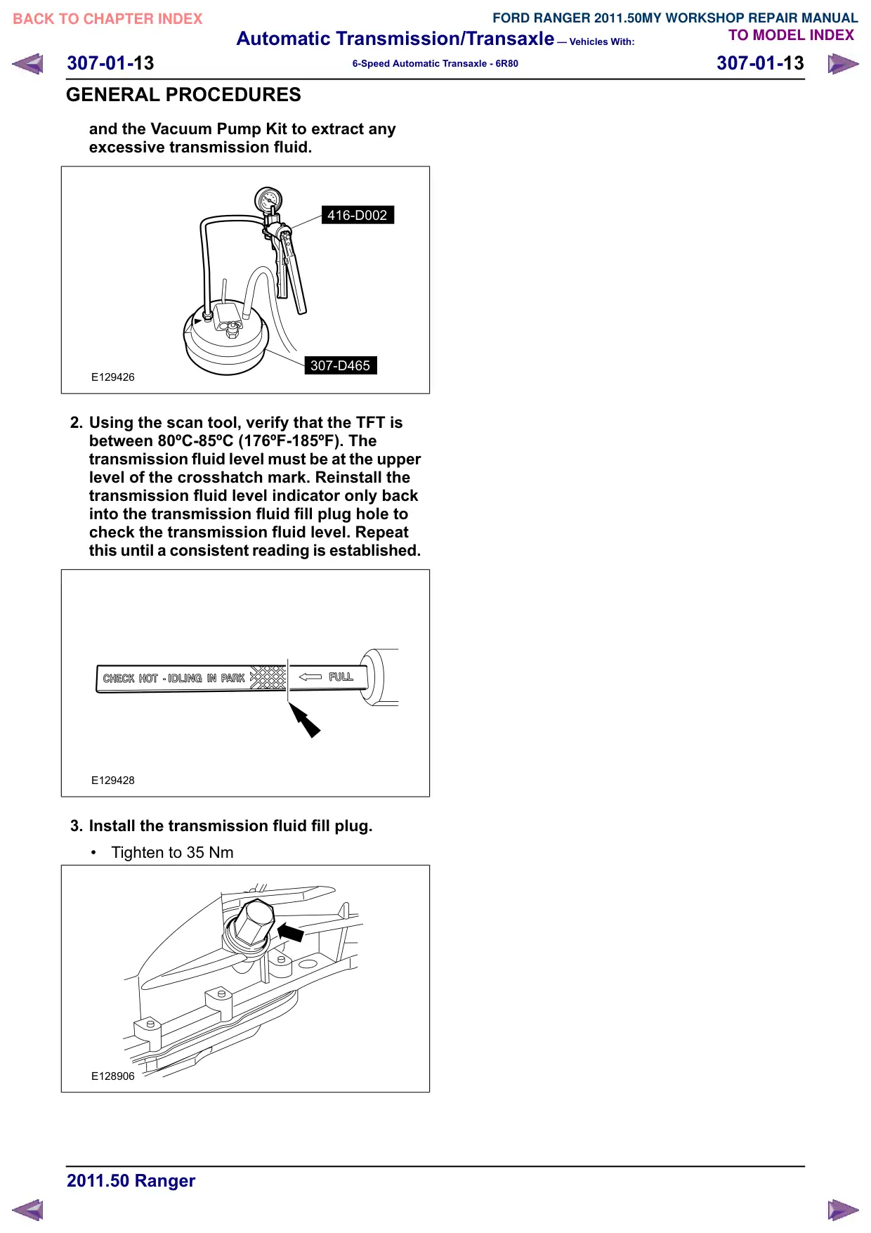
1. If the transmission is overfilled, transmission
fluid must be removed to the correct level.
Use the Transporter Fluid Evacuator/Injector
Automatic Transmission/Transaxle – Vehicles With:
307-01-13
307-01-13
6-Speed Automatic Transaxle - 6R80
GENERAL PROCEDURES
and the Vacuum Pump Kit to extract any
excessive transmission fluid.
416-D002
307-D465
E129426
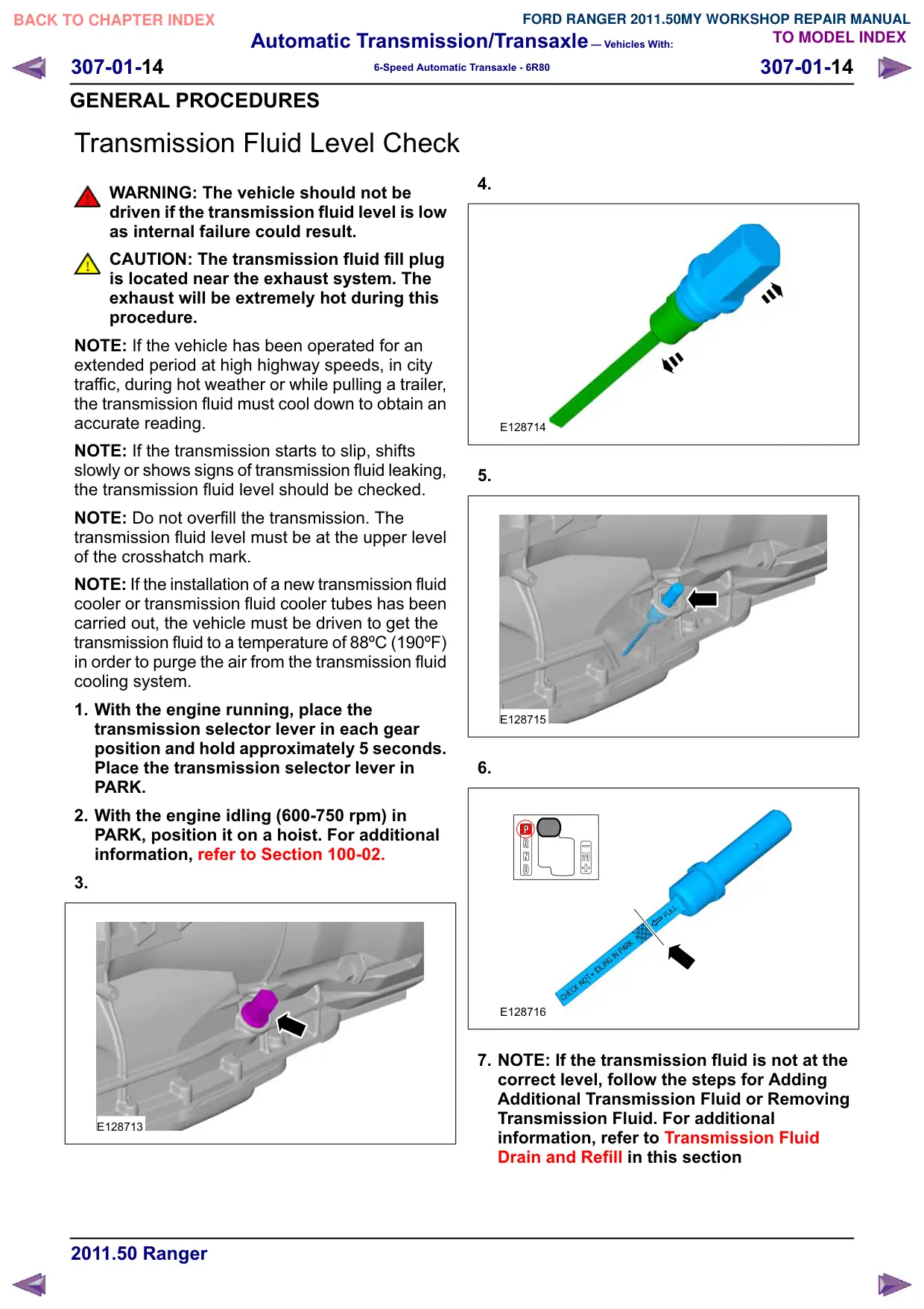
2. Using the scan tool, verify that the TFT is
between 80ºC-85ºC (176ºF-185ºF). The
transmission fluid level must be at the upper
level of the crosshatch mark. Reinstall the
transmission fluid level indicator only back
into the transmission fluid fill plug hole to
check the transmission fluid level. Repeat
this until a consistent reading is established.
E129428
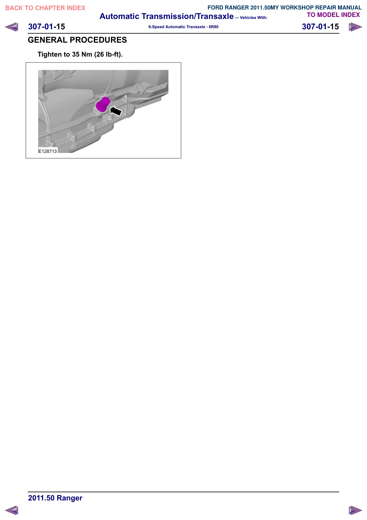
3. Install the transmission fluid fill plug.
Tighten to 35 Nm
E128906
Automatic Transmission/Transaxle – Vehicles With:
307-01-14
307-01-14
6-Speed Automatic Transaxle - 6R80
GENERAL PROCEDURES
Transmission Fluid Level Check
WARNING: The vehicle should not be
driven if the transmission fluid level is low
as internal failure could result.
CAUTION: The transmission fluid fill plug
is located near the exhaust system. The
exhaust will be extremely hot during this
procedure.
NOTE: If the vehicle has been operated for an
extended period at high highway speeds, in city
traffic, during hot weather or while pulling a trailer,
the transmission fluid must cool down to obtain an
accurate reading.
NOTE: If the transmission starts to slip, shifts
slowly or shows signs of transmission fluid leaking,
the transmission fluid level should be checked.
NOTE: Do not overfill the transmission. The
transmission fluid level must be at the upper level
of the crosshatch mark.
NOTE: If the installation of a new transmission fluid
cooler or transmission fluid cooler tubes has been
carried out, the vehicle must be driven to get the
transmission fluid to a temperature of 88ºC (190ºF)
in order to purge the air from the transmission fluid
cooling system.
1. With the engine running, place the
transmission selector lever in each gear
position and hold approximately 5 seconds.
Place the transmission selector lever in
PARK.
2. With the engine idling (600-750 rpm) in
PARK, position it on a hoist. For additional
information, refer to Section 100-02.
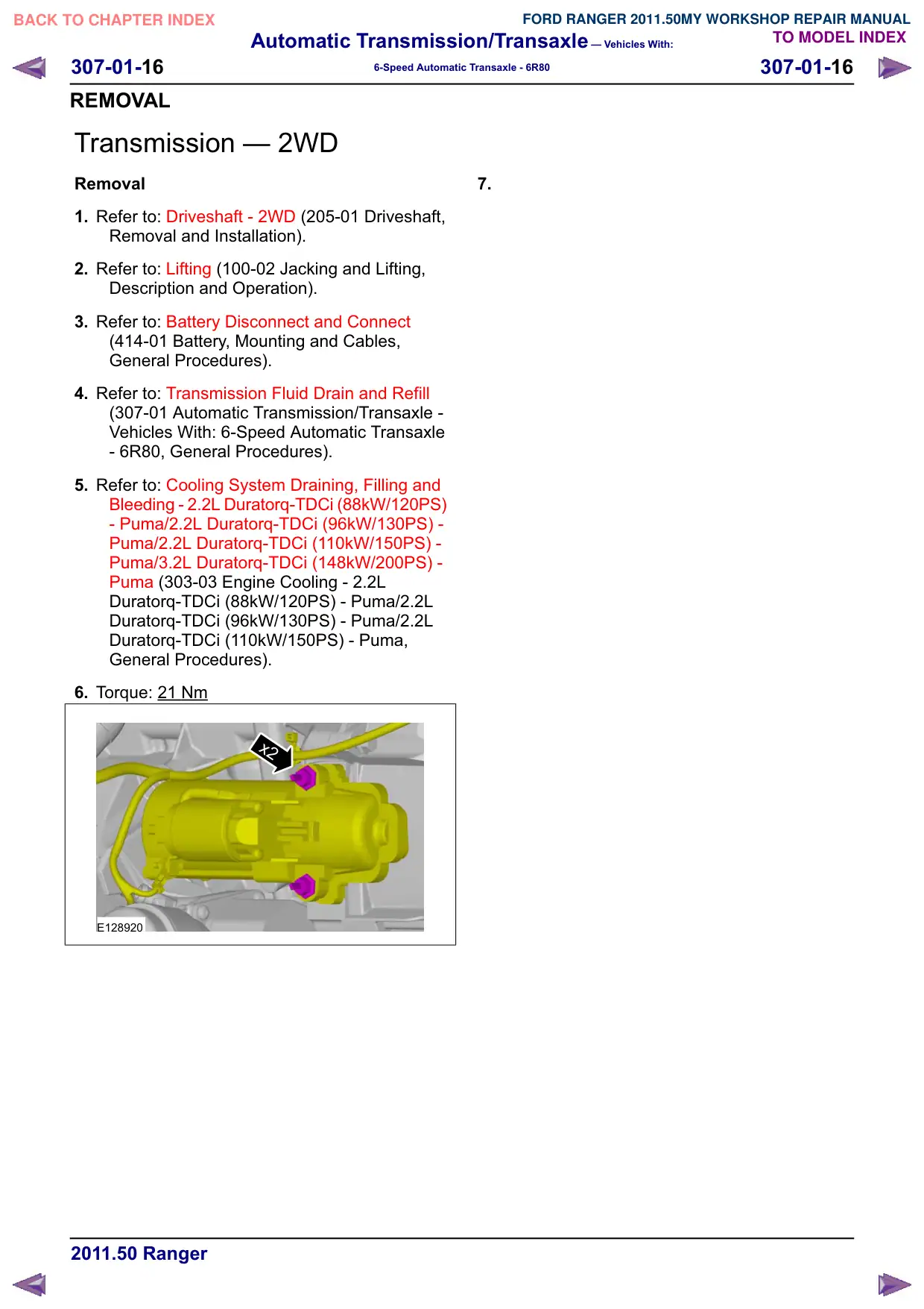
3.
E128713
4.
E128714
5.
E128715
6.
E128716
7. NOTE: If the transmission fluid is not at the
correct level, follow the steps for Adding
Additional Transmission Fluid or Removing
Transmission Fluid. For additional
information, refer to Transmission Fluid
Drain and Refill in this section
Automatic Transmission/Transaxle – Vehicles With:
307-01-17
307-01-17
6-Speed Automatic Transaxle - 6R80
REMOVAL
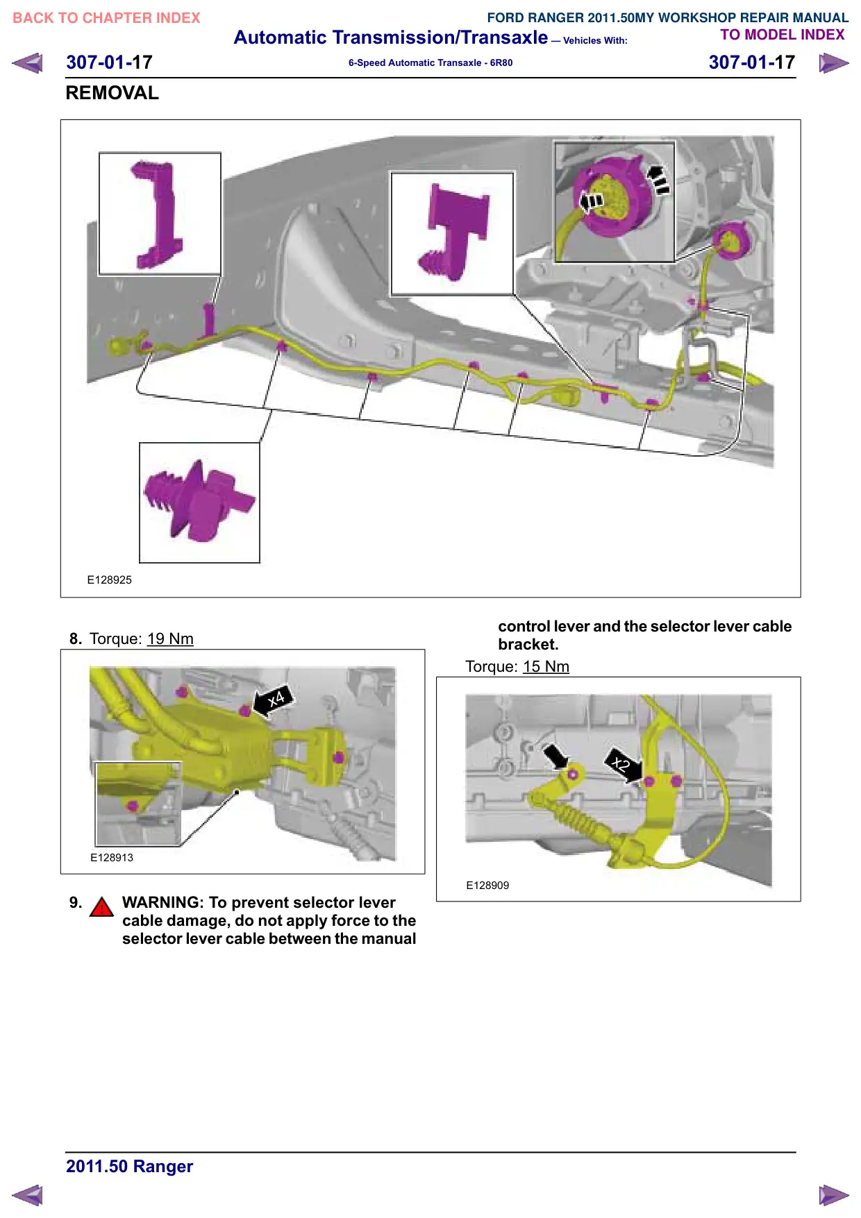
E128925
8. Torque: 19
Nm
x4
E128913
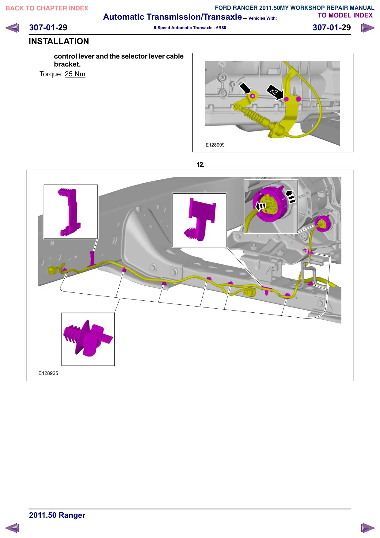
9.
WARNING: To prevent selector lever
cable damage, do not apply force to the
selector lever cable between the manual
control lever and the selector lever cable
bracket.
Torque: 15
Nm
x2
E128909
Automatic Transmission/Transaxle – Vehicles With:
307-01-18
307-01-18
6-Speed Automatic Transaxle - 6R80
REMOVAL
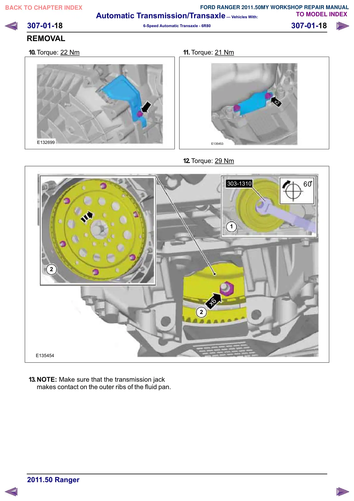
10.Torque: 22 Nm
E132699
2
E135454
13.NOTE: Make sure that the transmission jack
makes contact on the outer ribs of the fluid pan.
11. Torque: 21
Nm
x2
E135453
12.Torque: 29
Nm
60
303-1310
1
x6
2
Automatic Transmission/Transaxle – Vehicles With:
307-01-19
307-01-19
6-Speed Automatic Transaxle - 6R80
REMOVAL
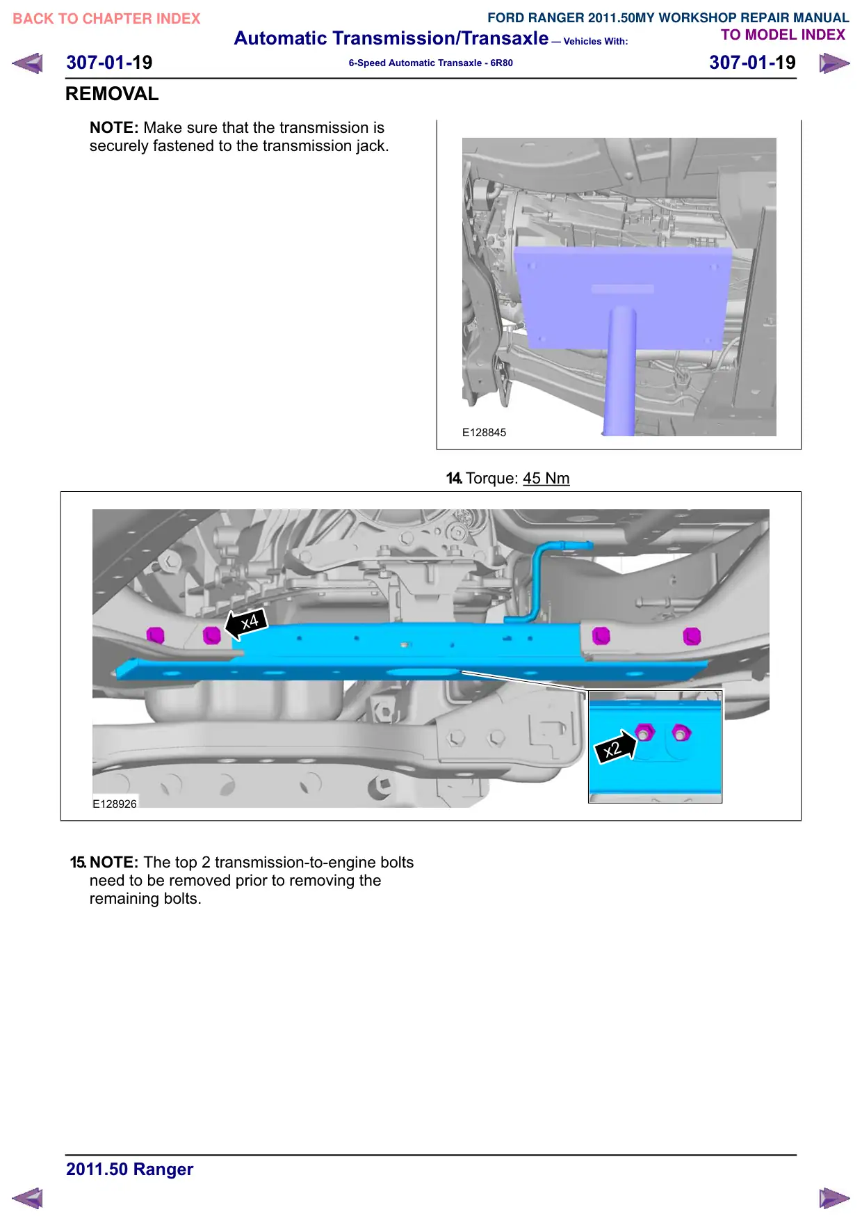
NOTE: Make sure that the transmission is
securely fastened to the transmission jack.
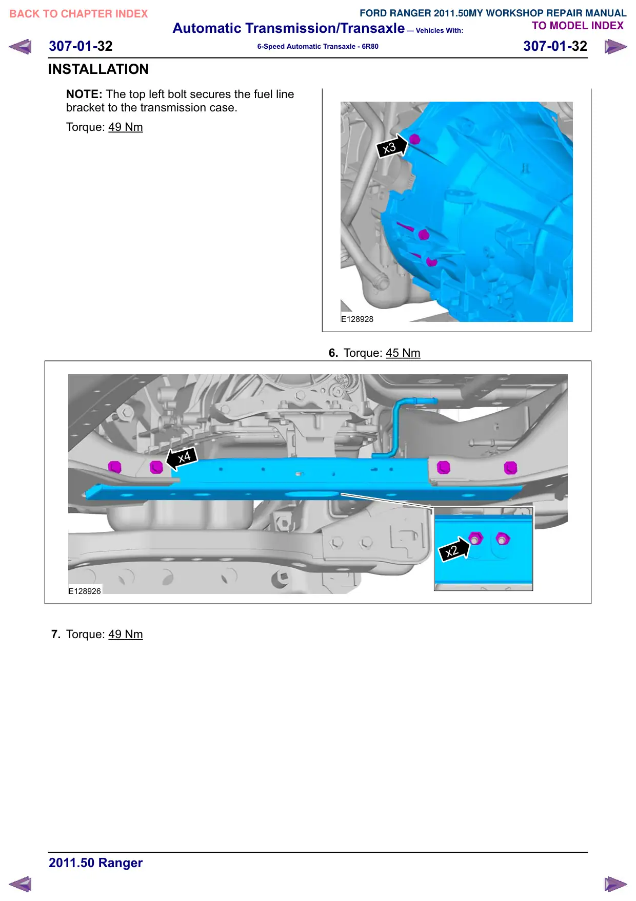
x4
E128926
15.NOTE: The top 2 transmission-to-engine bolts
need to be removed prior to removing the
remaining bolts.
E128845
14.Torque: 45 Nm
x2
Automatic Transmission/Transaxle – Vehicles With:
307-01-20
307-01-20
6-Speed Automatic Transaxle - 6R80
REMOVAL
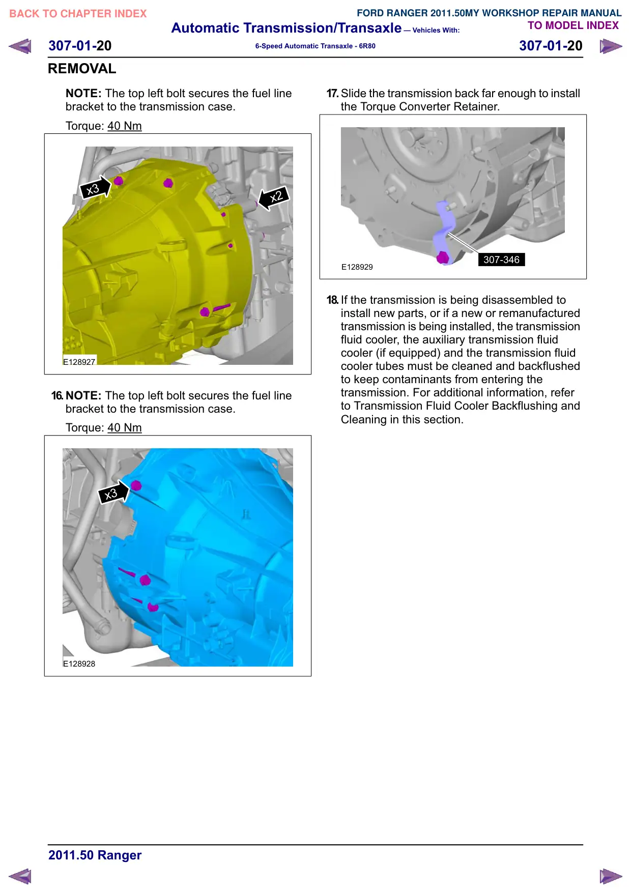
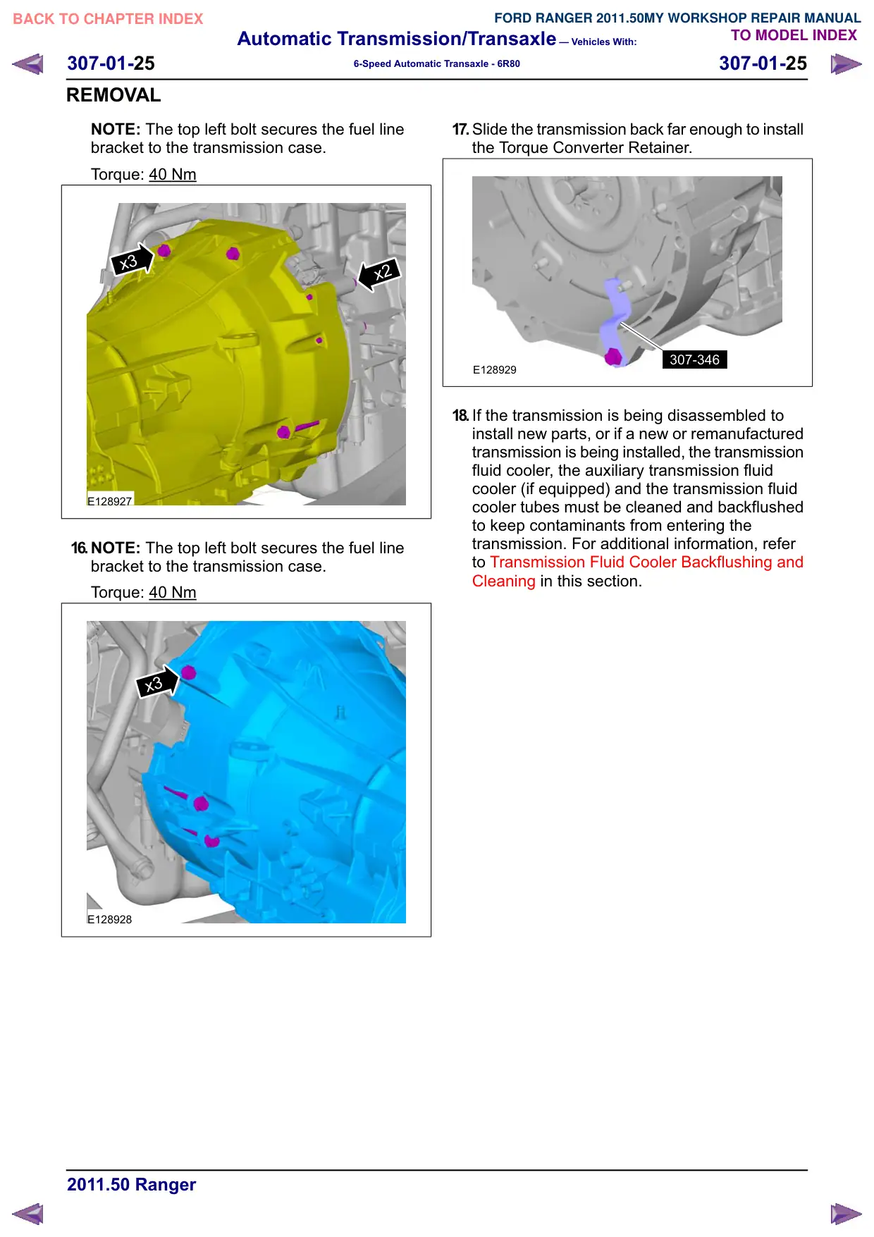
NOTE: The top left bolt secures the fuel line
bracket to the transmission case.
Torque: 40 Nm
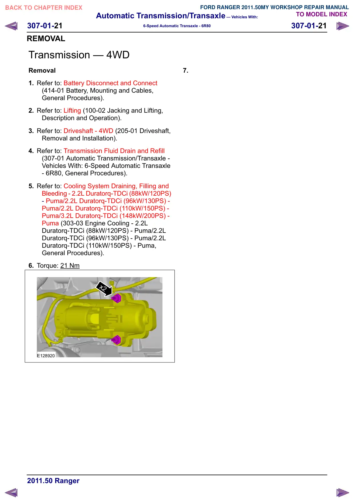
x3
x2
E128927
16.NOTE: The top left bolt secures the fuel line
bracket to the transmission case.
Torque: 40 Nm
x3
E128928
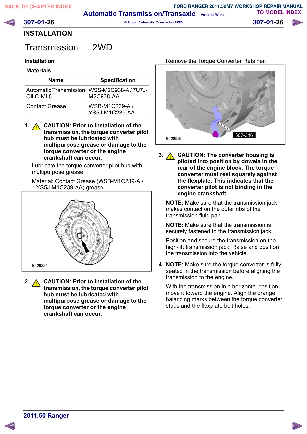
17.Slide the transmission back far enough to install
the Torque Converter Retainer.
307-346
E128929
18.If the transmission is being disassembled to
install new parts, or if a new or remanufactured
transmission is being installed, the transmission
fluid cooler, the auxiliary transmission fluid
cooler (if equipped) and the transmission fluid
cooler tubes must be cleaned and backflushed
to keep contaminants from entering the
transmission. For additional information, refer
to Transmission Fluid Cooler Backflushing and
Cleaning in this section.
Automatic Transmission/Transaxle – Vehicles With:
307-01-22
307-01-22
6-Speed Automatic Transaxle - 6R80
REMOVAL
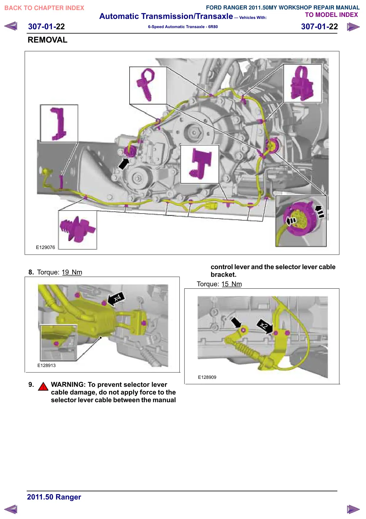
E129076
8. Torque: 19
Nm
x4
E128913
9.
WARNING: To prevent selector lever
cable damage, do not apply force to the
selector lever cable between the manual
control lever and the selector lever cable
bracket.
Torque: 15
Nm
x2
E128909
Automatic Transmission/Transaxle – Vehicles With:
307-01-23
307-01-23
6-Speed Automatic Transaxle - 6R80
REMOVAL
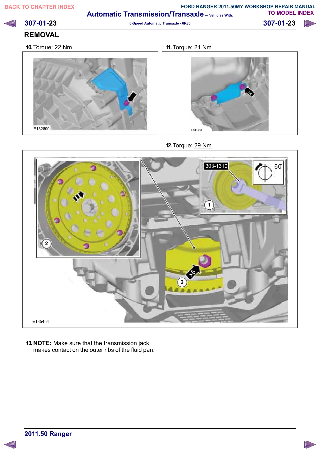
10.Torque: 22 Nm
E132699
2
E135454
13.NOTE: Make sure that the transmission jack
makes contact on the outer ribs of the fluid pan.
11. Torque: 21
Nm
x2
E135453
12.Torque: 29
Nm
60
303-1310
1
x6
2
Automatic Transmission/Transaxle – Vehicles With:
307-01-24
307-01-24
6-Speed Automatic Transaxle - 6R80
REMOVAL
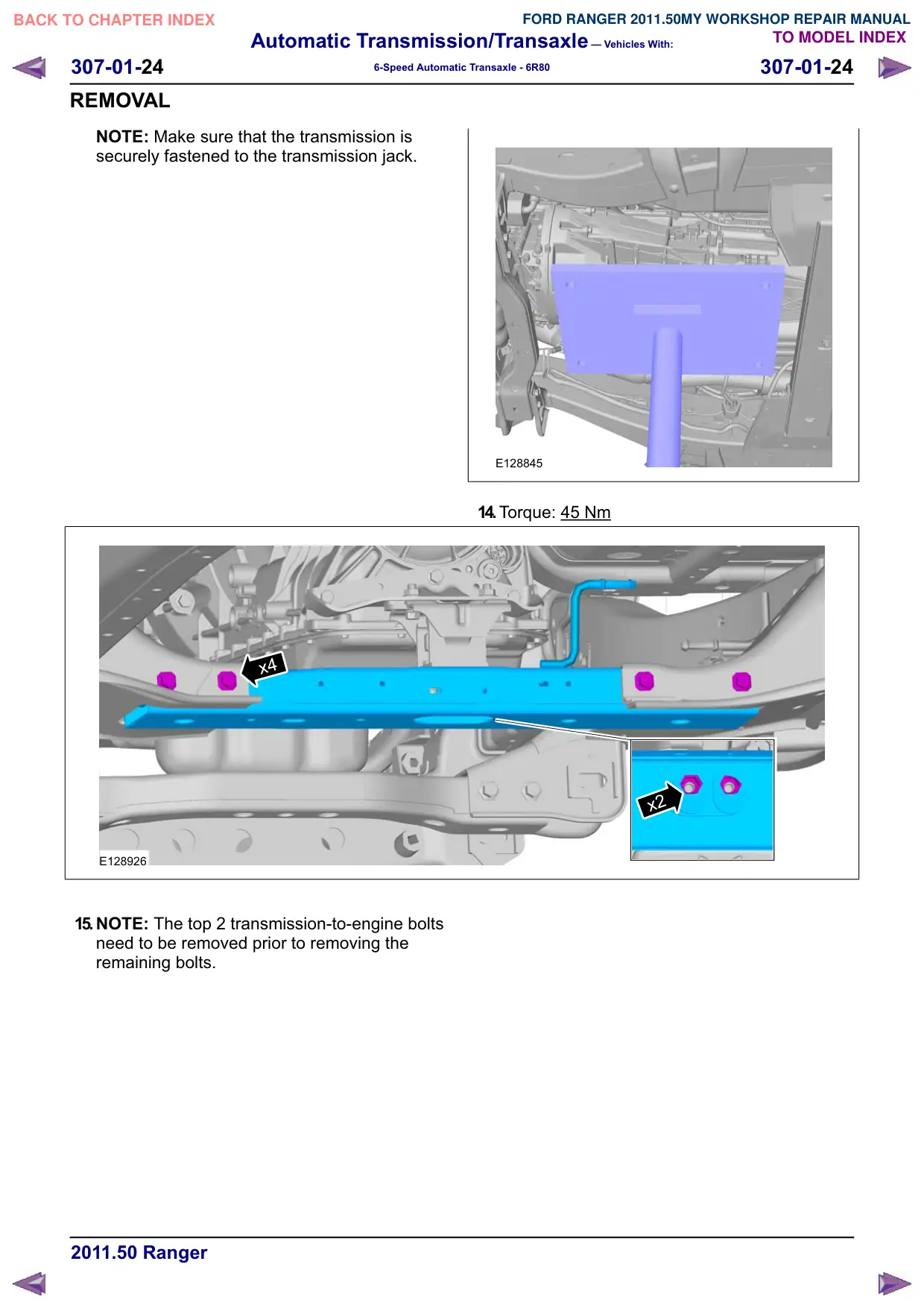
NOTE: Make sure that the transmission is
securely fastened to the transmission jack.
x4
E128926
15.NOTE: The top 2 transmission-to-engine bolts
need to be removed prior to removing the
remaining bolts.
E128845
14.Torque: 45 Nm
x2
Automatic Transmission/Transaxle – Vehicles With:
307-01-25
307-01-25
6-Speed Automatic Transaxle - 6R80
REMOVAL
NOTE: The top left bolt secures the fuel line
bracket to the transmission case.
Torque: 40 Nm
x3
x2
E128927
16.NOTE: The top left bolt secures the fuel line
bracket to the transmission case.
Torque: 40 Nm
x3
E128928
17.Slide the transmission back far enough to install
the Torque Converter Retainer.
307-346
E128929
18.If the transmission is being disassembled to
install new parts, or if a new or remanufactured
transmission is being installed, the transmission
fluid cooler, the auxiliary transmission fluid
cooler (if equipped) and the transmission fluid
cooler tubes must be cleaned and backflushed
to keep contaminants from entering the
transmission. For additional information, refer
to Transmission Fluid Cooler Backflushing and
Cleaning in this section.
Automatic Transmission/Transaxle – Vehicles With:
307-01-26
307-01-26
6-Speed Automatic Transaxle - 6R80
INSTALLATION
Transmission – 2WD
Installation
Materials
Name
Specification
Automatic Transmission
WSS-M2C938-A / 7U7J-
Oil C-ML5
M2C938-AA
Contact Grease
WSB-M1C239-A /
YS5J-M1C239-AA
1.
CAUTION: Prior to installation of the
transmission, the torque converter pilot
hub must be lubricated with
multipurpose grease or damage to the
torque converter or the engine
crankshaft can occur.
Lubricate the torque converter pilot hub with
multipurpose grease.
Material: Contact Grease (WSB-M1C239-A /
YS5J-M1C239-AA) grease
E129224
2.
CAUTION: Prior to installation of the
transmission, the torque converter pilot
hub must be lubricated with
multipurpose grease or damage to the
torque converter or the engine
crankshaft can occur.
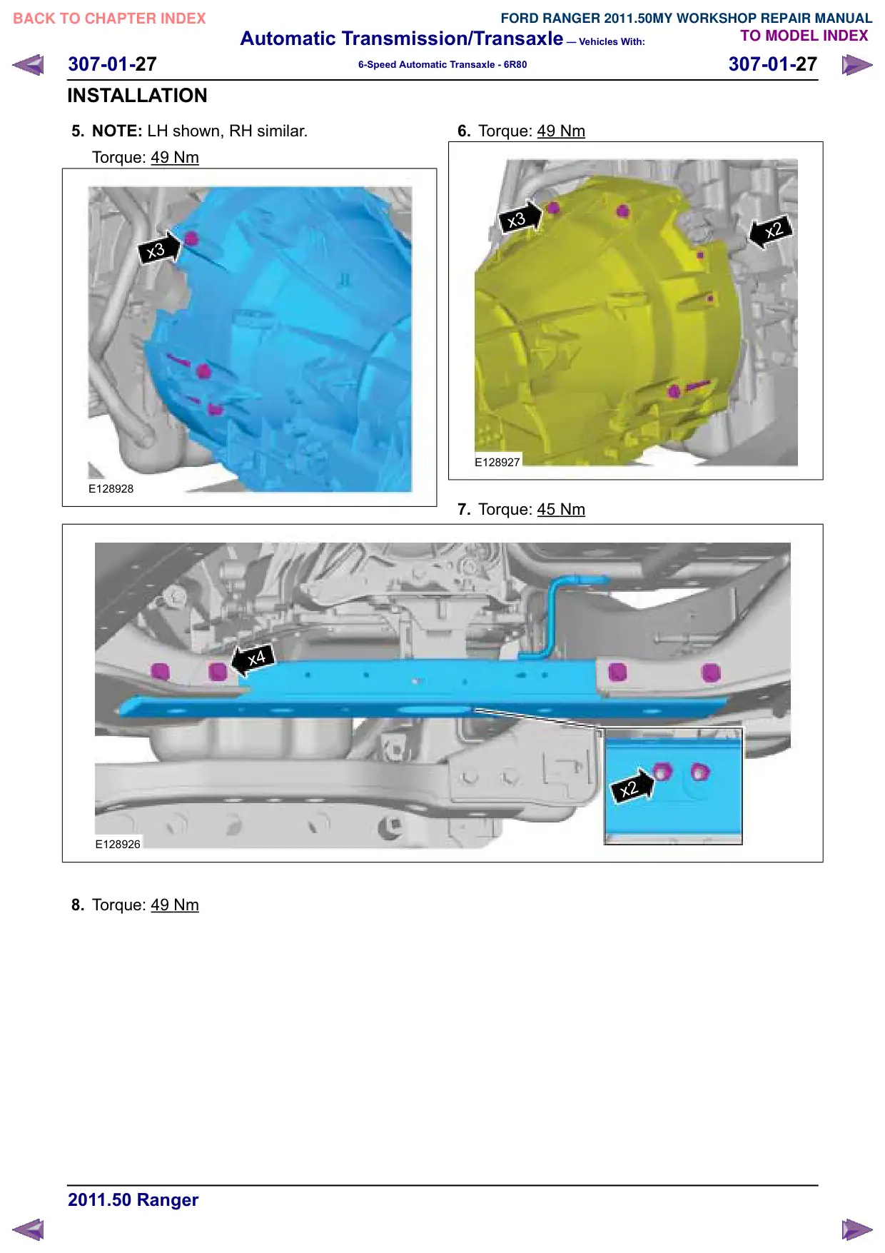
Remove the Torque Converter Retainer.
307-346
E128929
3.
CAUTION: The converter housing is
piloted into position by dowels in the
rear of the engine block. The torque
converter must rest squarely against
the flexplate. This indicates that the
converter pilot is not binding in the
engine crankshaft.
NOTE: Make sure that the transmission jack
makes contact on the outer ribs of the
transmission fluid pan.
NOTE: Make sure that the transmission is
securely fastened to the transmission jack.
Position and secure the transmission on the
high-lift transmission jack. Raise and position
the transmission into the vehicle.
4. NOTE: Make sure the torque converter is fully
seated in the transmission before aligning the
transmission to the engine.
With the transmission in a horizontal position,
move it toward the engine. Align the orange
balancing marks between the torque converter
studs and the flexplate bolt holes.
Automatic Transmission/Transaxle – Vehicles With:
307-01-28
307-01-28
6-Speed Automatic Transaxle - 6R80
INSTALLATION
2
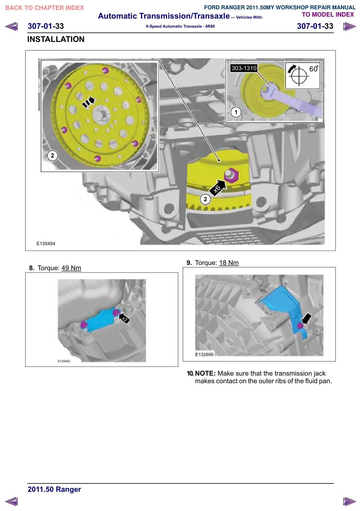
E135454
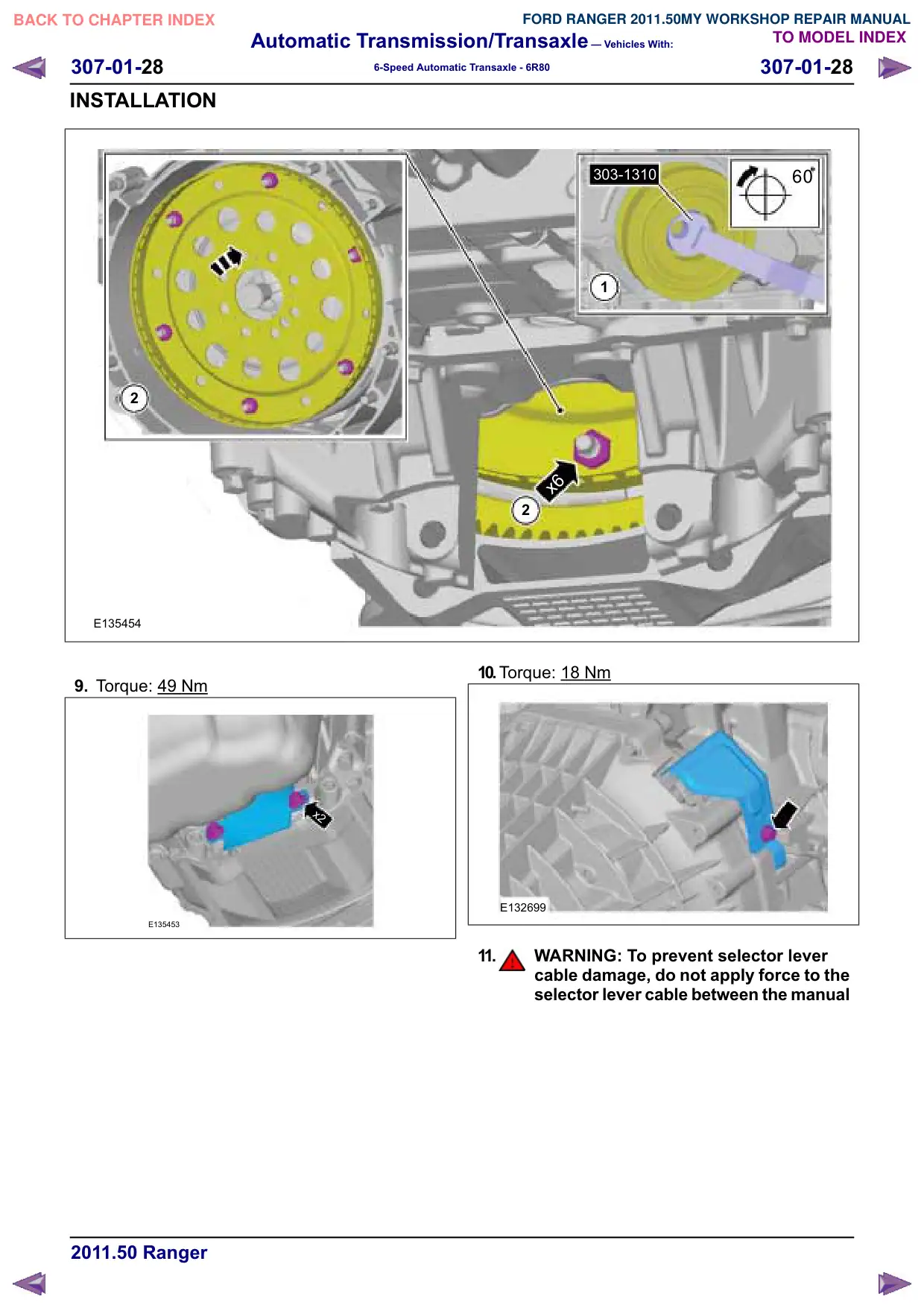
9. Torque: 49 Nm
x2
E135453
303-1310
60
1
x6
2
10.Torque: 18
Nm
E132699
11.
WARNING: To prevent selector lever
cable damage, do not apply force to the
selector lever cable between the manual
Automatic Transmission/Transaxle – Vehicles With:
307-01-30
307-01-30
6-Speed Automatic Transaxle - 6R80
INSTALLATION
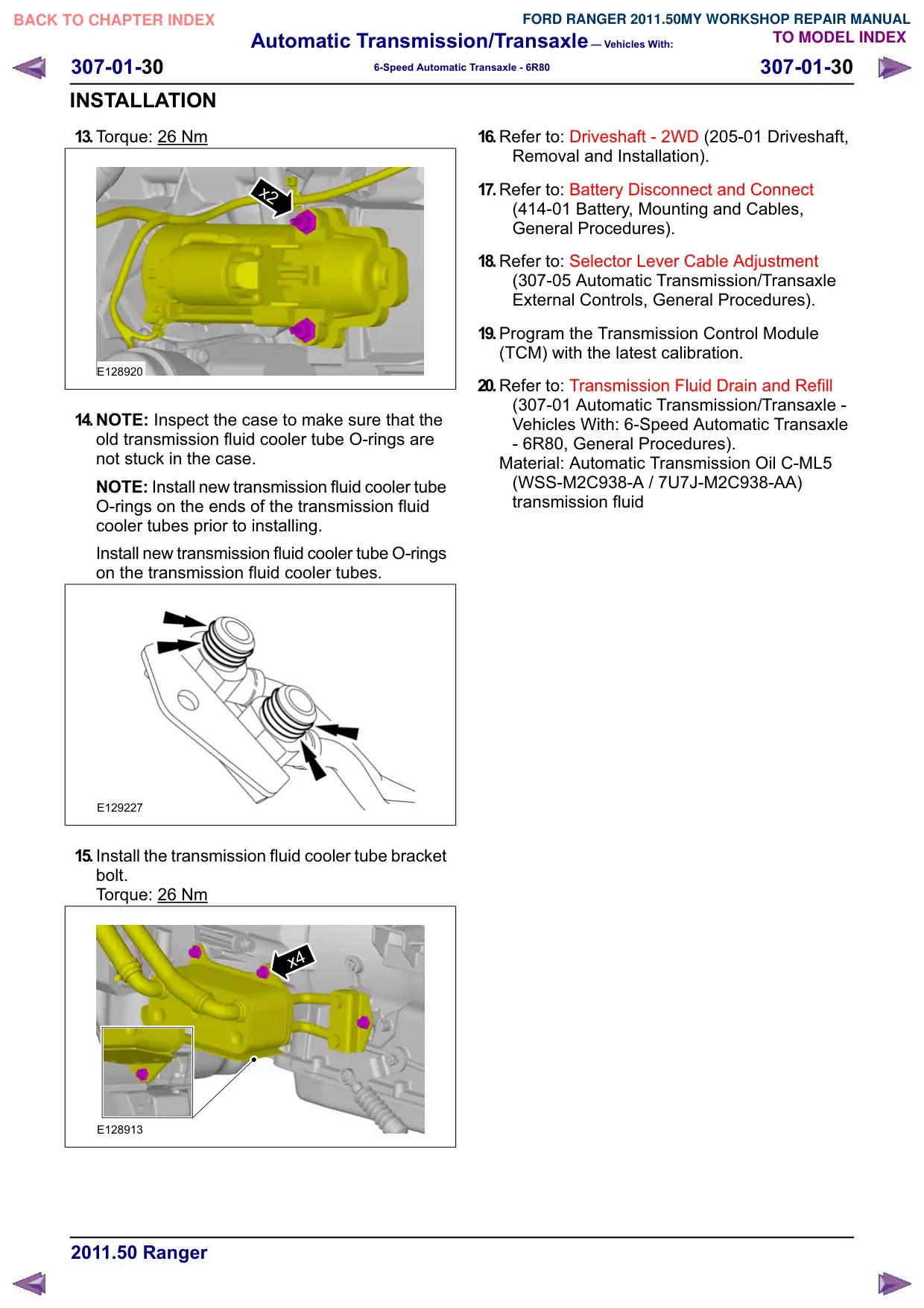
13.Torque: 26 Nm
x2
E128920
14.NOTE: Inspect the case to make sure that the
old transmission fluid cooler tube O-rings are
not stuck in the case.
NOTE: Install new transmission fluid cooler tube
O-rings on the ends of the transmission fluid
cooler tubes prior to installing.
Install new transmission fluid cooler tube O-rings
on the transmission fluid cooler tubes.
E129227
15.Install the transmission fluid cooler tube bracket
bolt.
Torque: 26 Nm
x4
E128913
16.Refer to: Driveshaft - 2WD (205-01 Driveshaft,
Removal and Installation).
17.Refer to: Battery Disconnect and Connect
(414-01 Battery, Mounting and Cables,
General Procedures).
18.Refer to: Selector Lever Cable Adjustment
(307-05 Automatic Transmission/Transaxle
External Controls, General Procedures).
19.Program the Transmission Control Module
(TCM) with the latest calibration.
20.Refer to: Transmission Fluid Drain and Refill
(307-01 Automatic Transmission/Transaxle -
Vehicles With: 6-Speed Automatic Transaxle
- 6R80, General Procedures).
Material: Automatic Transmission Oil C-ML5
(WSS-M2C938-A / 7U7J-M2C938-AA)
transmission fluid
Automatic Transmission/Transaxle – Vehicles With:
307-01-31
307-01-31
6-Speed Automatic Transaxle - 6R80
INSTALLATION
Transmission – 4WD
Installation
Materials
Name
Specification
Contact Grease
WSB-M1C239-A /
YS5J-M1C239-AA
1. Refer to: Lifting (100-02 Jacking and Lifting,
Description and Operation).
2.
CAUTION: Prior to installation of the
transmission, the torque converter pilot
hub must be lubricated with
multipurpose grease or damage to the
torque converter or the engine
crankshaft can occur.
Lubricate the torque converter pilot hub with
multipurpose grease.
Material: Contact Grease (WSB-M1C239-A /
YS5J-M1C239-AA) grease
E129224
3.
CAUTION: The converter housing is
piloted into position by dowels in the
rear of the engine block. The torque
converter must rest squarely against
the flexplate. This indicates that the
converter pilot is not binding in the
engine crankshaft.
NOTE: Make sure that the transmission jack
makes contact on the outer ribs of the
transmission fluid pan.
NOTE: Make sure that the transmission is
securely fastened to the transmission jack.
Position and secure the transmission on the
high-lift transmission jack. Raise and position
the transmission into the vehicle.
307-346
E128929
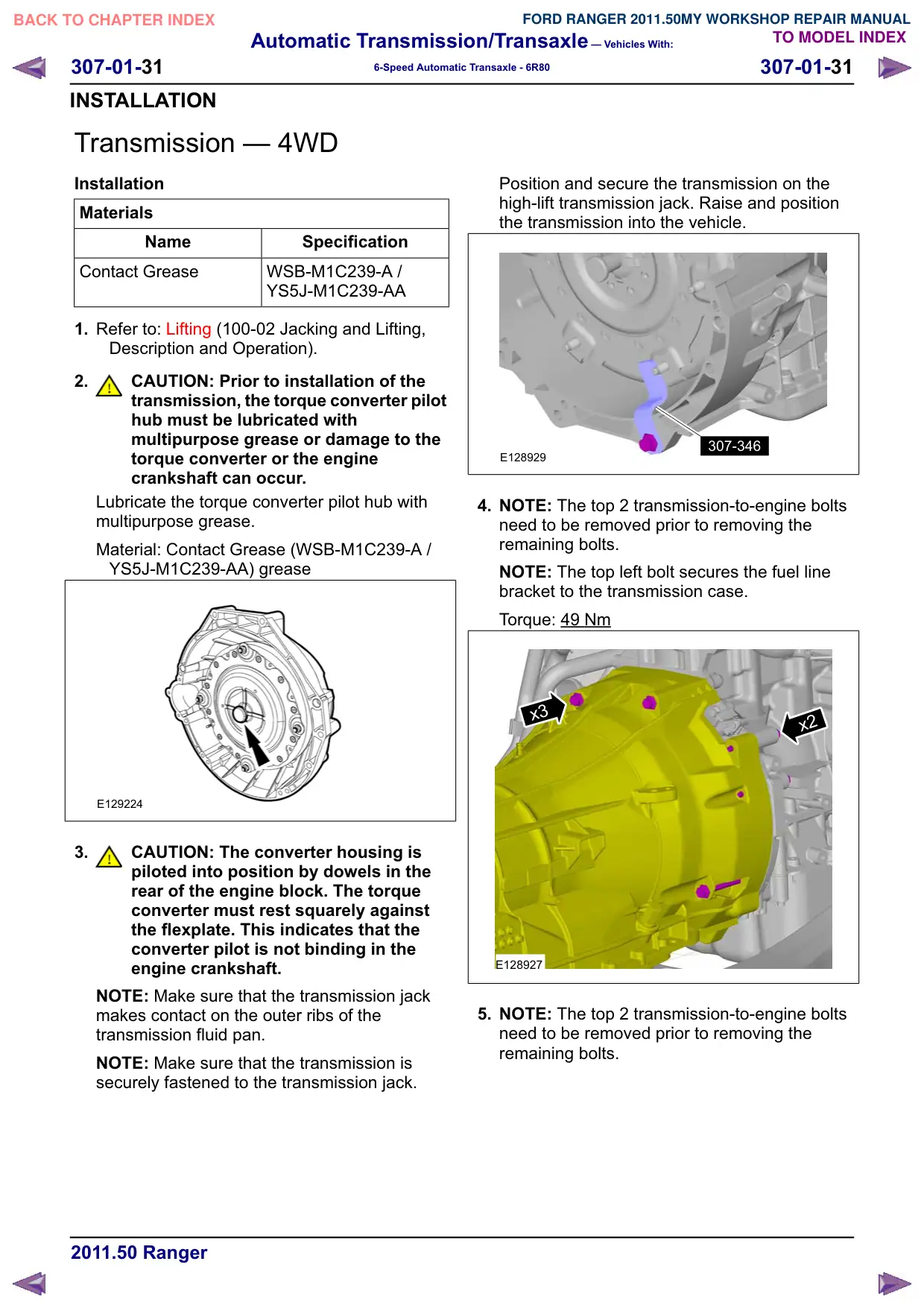
4. NOTE: The top 2 transmission-to-engine bolts
need to be removed prior to removing the
remaining bolts.
NOTE: The top left bolt secures the fuel line
bracket to the transmission case.
Torque: 49 Nm
x3
x2
E128927
5. NOTE: The top 2 transmission-to-engine bolts
need to be removed prior to removing the
remaining bolts.
Automatic Transmission/Transaxle – Vehicles With:
307-01-33
307-01-33
6-Speed Automatic Transaxle - 6R80
INSTALLATION
2
E135454
8. Torque: 49
Nm
x2
E135453
303-1310
60
1
x6
2
9. Torque: 18
Nm
E132699
10.NOTE: Make sure that the transmission jack
makes contact on the outer ribs of the fluid pan.
Automatic Transmission/Transaxle – Vehicles With:
307-01-34
307-01-34
6-Speed Automatic Transaxle - 6R80
INSTALLATION
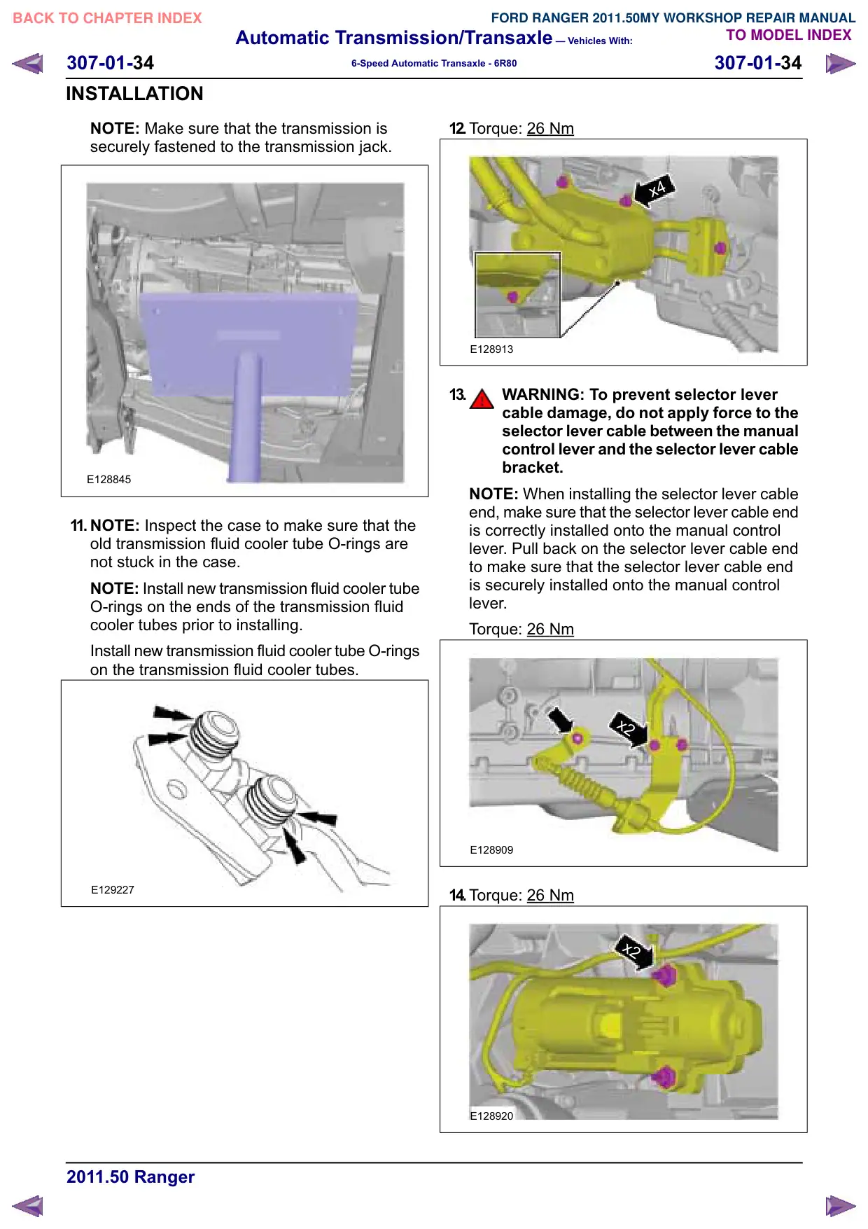
NOTE: Make sure that the transmission is
securely fastened to the transmission jack.
E128845
11. NOTE: Inspect the case to make sure that the
old transmission fluid cooler tube O-rings are
not stuck in the case.
NOTE: Install new transmission fluid cooler tube
O-rings on the ends of the transmission fluid
cooler tubes prior to installing.
Install new transmission fluid cooler tube O-rings
on the transmission fluid cooler tubes.
E129227
12.Torque: 26 Nm
x4
E128913
13.
WARNING: To prevent selector lever
cable damage, do not apply force to the
selector lever cable between the manual
control lever and the selector lever cable
bracket.
NOTE: When installing the selector lever cable
end, make sure that the selector lever cable end
is correctly installed onto the manual control
lever. Pull back on the selector lever cable end
to make sure that the selector lever cable end
is securely installed onto the manual control
lever.
Torque: 26
Nm
x2
E128909
14.Torque: 26
Nm
x2
E128920