Body Repairs - Vehicle Specific Information
501-26-1
and Tolerance Checks
501-26-1
.
SECTION 501-26 Body Repairs - Vehicle Specific
Information and Tolerance Checks
VEHICLE APPLICATION: 2011.50 Ranger
CONTENTS
DESCRIPTION AND OPERATION
Body and Frame (Component Location)............................................................................
Body and Frame (Overview)...............................................................................................
Introduction.........................................................................................................................
High-strength and super-high-strength steels ...................................................................
Usibor steel.........................................................................................................................
Single cab ......................................................................................................................
Double cab......................................................................................................................
Super cab........................................................................................................................
Sheet metal parts for quarter panel partial replacement ...................................................
Single cab.......................................................................................................................
Double cab......................................................................................................................
Super cab........................................................................................................................
Anti corrosion protection.....................................................................................................
GENERAL PROCEDURES
Underbody Tolerance Check..............................................................................................
Frame Tolerance Check.....................................................................................................
PAGE
501-26-2
501-26-11
501-26-11
501-26-11
501-26-11
501-26-11
501-26-12
501-26-12
501-26-13
501-26-13
501-26-13
501-26-14
501-26-14
501-26-16
501-26-18
Body Repairs - Vehicle Specific Information
501-26-2
and Tolerance Checks
501-26-2
DESCRIPTION AND OPERATION
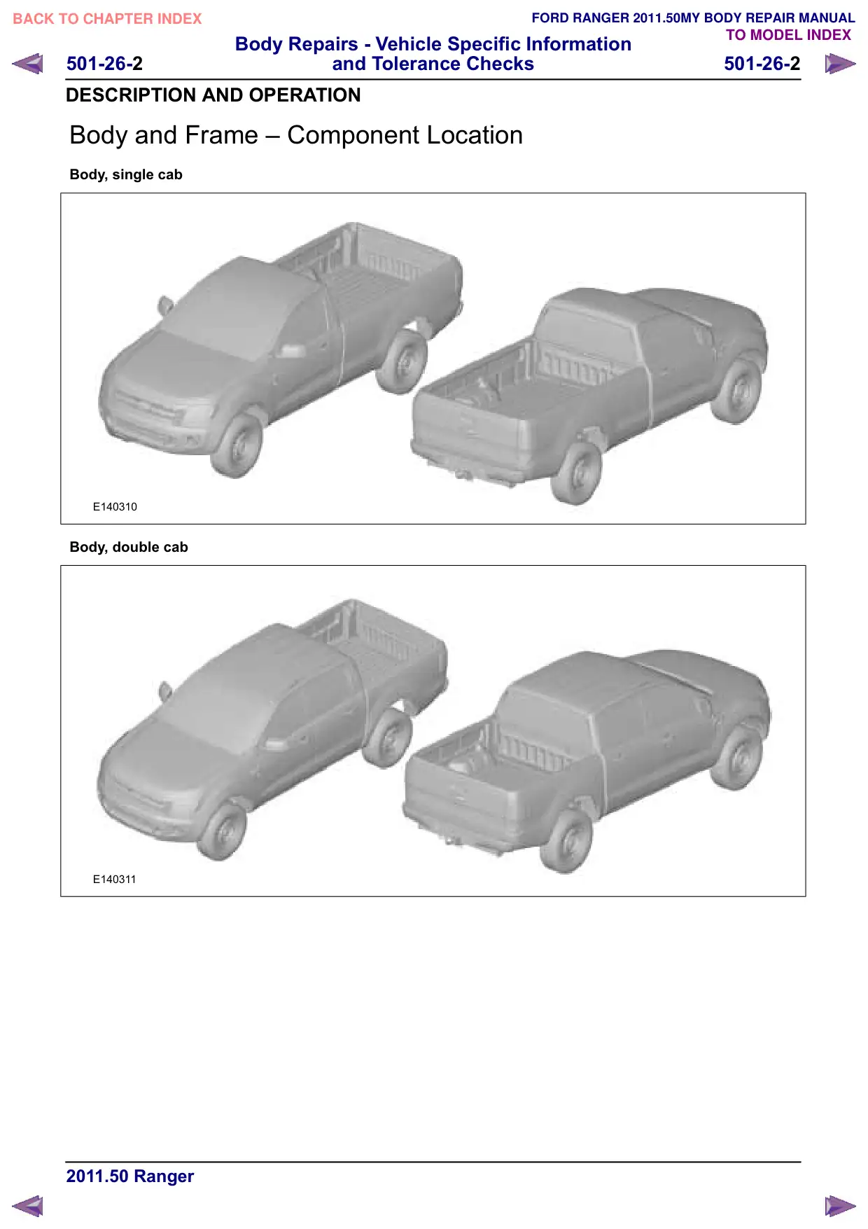
Body and Frame œ Component Location
Body, single cab
E140310
Body, double cab
E140311
Body Repairs - Vehicle Specific Information
501-26-3
and Tolerance Checks
501-26-3
DESCRIPTION AND OPERATION
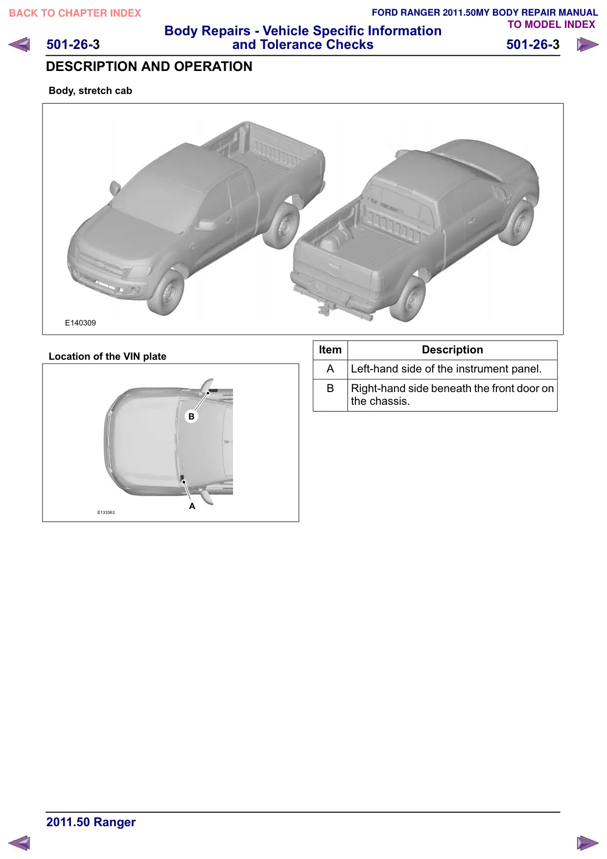
Body, stretch cab
E140309
Location of the VIN plate
%
$
E133363
Item
Description
$
Left-hand side of the instrument panel.
%
Right-hand side beneath the front door on
the chassis.
Body Repairs - Vehicle Specific Information
501-26-5
and Tolerance Checks
501-26-5
DESCRIPTION AND OPERATION
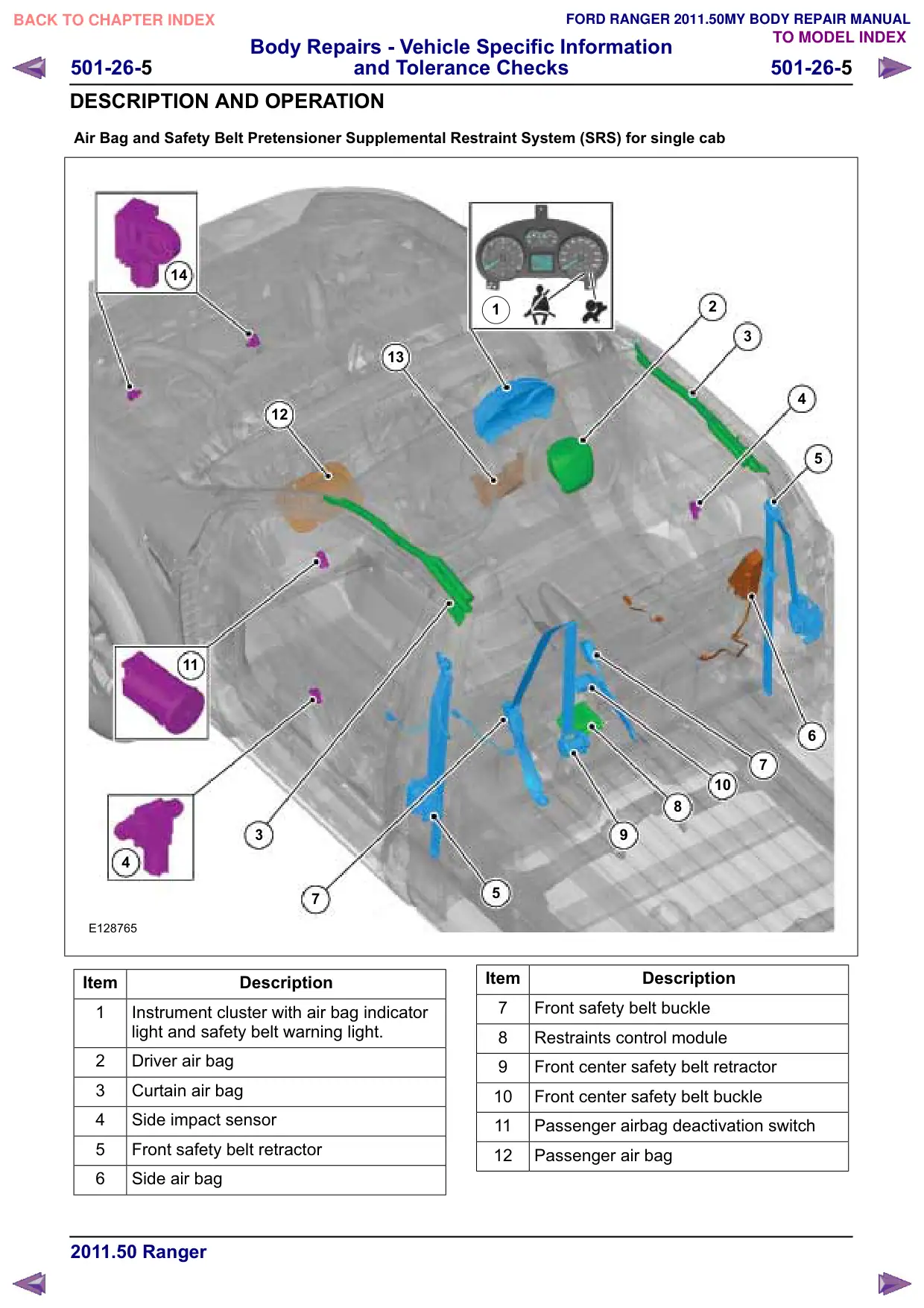
Air Bag and Safety Belt Pretensioner Supplemental Restraint System (SRS) for single cab
14
13
12
11
3
4
7
E128765
Item
Description
1
Instrument cluster with air bag indicator
light and safety belt warning light.
2
Driver air bag
3
Curtain air bag
4
Side impact sensor
5
Front safety belt retractor
6
Side air bag
2
1
3
4
5
6
7
10
8
5
Item
Description
7
Front safety belt buckle
8
Restraints control module
Front center safety belt retractor
10
Front center safety belt buckle
11
Passenger airbag deactivation switch
12
Passenger air bag
Body Repairs - Vehicle Specific Information
501-26-6
and Tolerance Checks
501-26-6
DESCRIPTION AND OPERATION
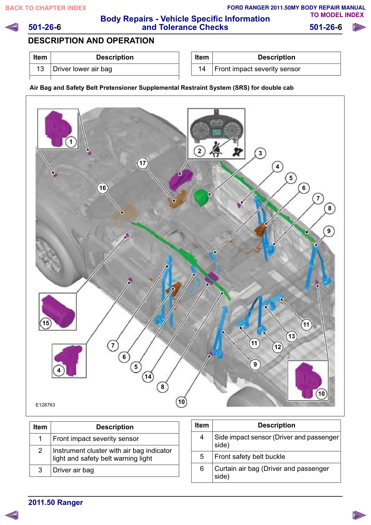
Item
Description
13
Driver lower air bag
Air Bag and Safety Belt Pretensioner Supplemental Restraint System (SRS) for double cab
1
17
16
15
7
6
5
4
14
8
E128763
Item
Description
1
Front impact severity sensor
2
Instrument cluster with air bag indicator
light and safety belt warning light
3
Driver air bag
Item
Description
14
Front impact severity sensor
2
3
4
5
6
7
8
11
13
11
12
10
10
Item
Description
4
Side impact sensor (Driver and passenger
side)
5
Front safety belt buckle
6
Curtain air bag (Driver and passenger
side)
Body Repairs - Vehicle Specific Information
501-26-7
and Tolerance Checks
501-26-7
DESCRIPTION AND OPERATION
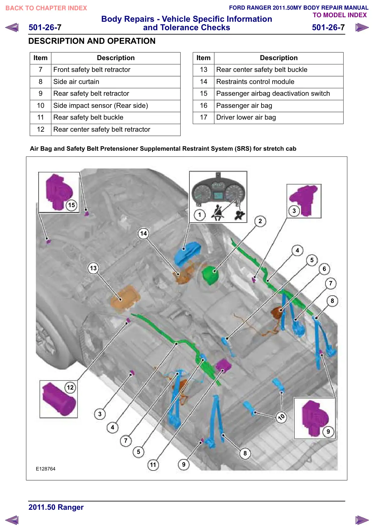
Item
Description
7
Front safety belt retractor
8
Side air curtain
Rear safety belt retractor
10
Side impact sensor (Rear side)
11
Rear safety belt buckle
12
Rear center safety belt retractor
Air Bag and Safety Belt Pretensioner Supplemental Restraint System (SRS) for stretch cab
15
14
13
12
3
4
7
5
11
E128764
Item
Description
13
Rear center safety belt buckle
14
Restraints control module
15
Passenger airbag deactivation switch
16
Passenger air bag
17
Driver lower air bag
3
1
2
4
5
6
7
8
10
8
Body Repairs - Vehicle Specific Information
501-26-8
and Tolerance Checks
501-26-8
DESCRIPTION AND OPERATION
Item
Description
1
Instrument cluster with air bag indicator
light and safety belt warning light
2
Driver air bag
3
Side impact sensor (Driver and passenger
side)
4
Curtain air bag
5
Front safety belt buckle
6
Side air bag (Driver and passenger side)
7
Front safety belt retractor
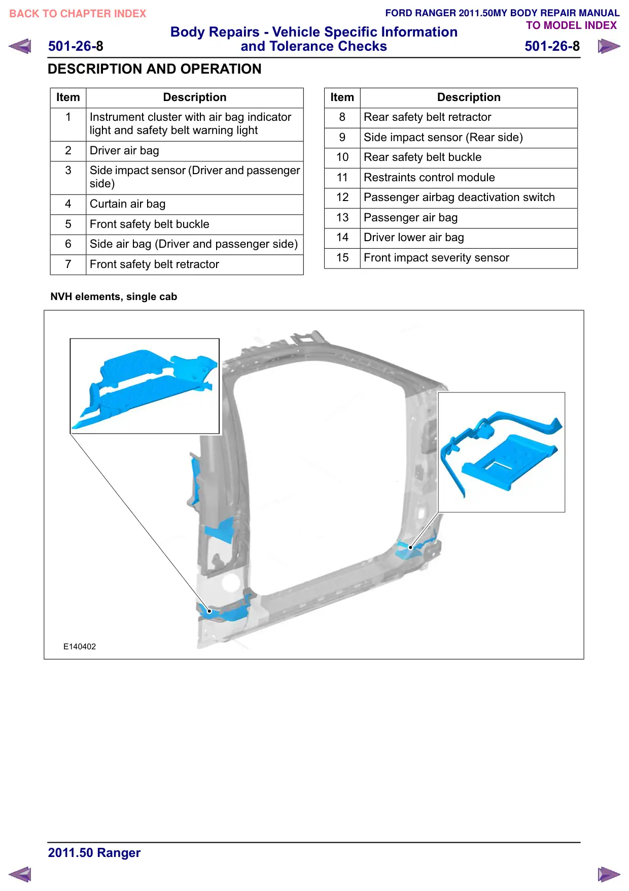
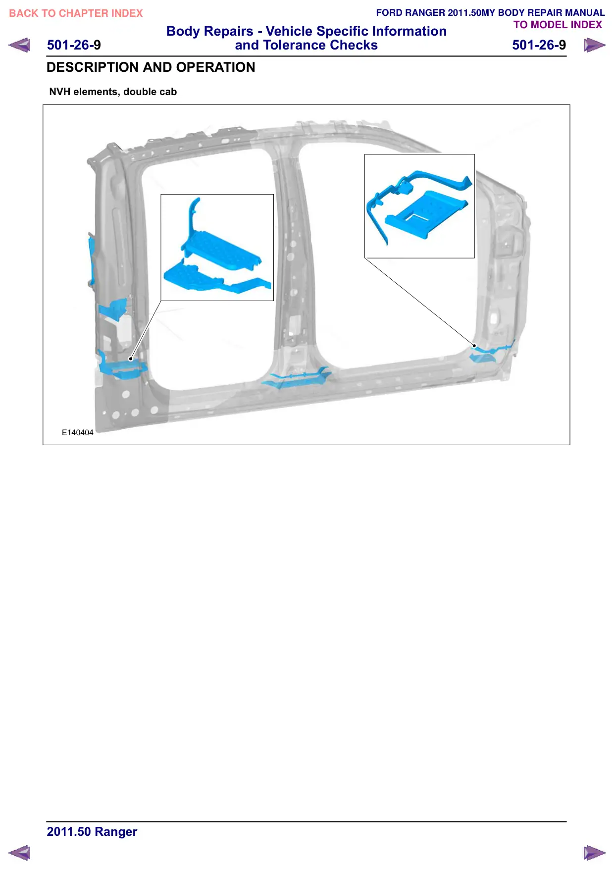
NVH elements, single cab
E140402
Item
Description
8
Rear safety belt retractor
Side impact sensor (Rear side)
10
Rear safety belt buckle
11
Restraints control module
12
Passenger airbag deactivation switch
13
Passenger air bag
14
Driver lower air bag
15
Front impact severity sensor
Body Repairs - Vehicle Specific Information
501-26-11
and Tolerance Checks
501-26-11
DESCRIPTION AND OPERATION
Body and Frame œ Overview
Introduction
With the 2011.25 model year, the Ford Ranger is
superseded by a completely new vehicle. The T6
is based on the U1 platform which has been
developed in co-operation with Mazda. 2-door and
4-door body versions are offered. Within the
company the model designation is P375. Overall
the vehicle weighs less than its predecessor.
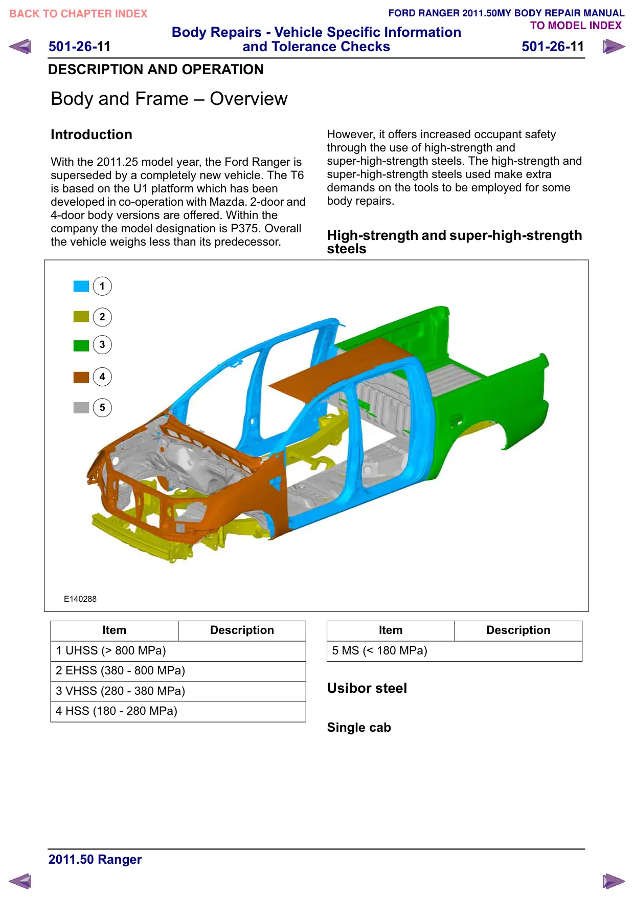
1
2
3
4
5
E140288
Item
Description
1 UHSS (> 800 MPa)
2 EHSS (380 - 800 MPa)
3 VHSS (280 - 380 MPa)
4 HSS (180 - 280 MPa)
However, it offers increased occupant safety
through the use of high-strength and
super-high-strength steels. The high-strength and
super-high-strength steels used make extra
demands on the tools to be employed for some
body repairs.
High-strength and super-high-strength
steels
Item
Description
5 MS (< 180 MPa)
Usibor steel
Single cab
Body Repairs - Vehicle Specific Information
501-26-13
and Tolerance Checks
501-26-13
DESCRIPTION AND OPERATION
E140246
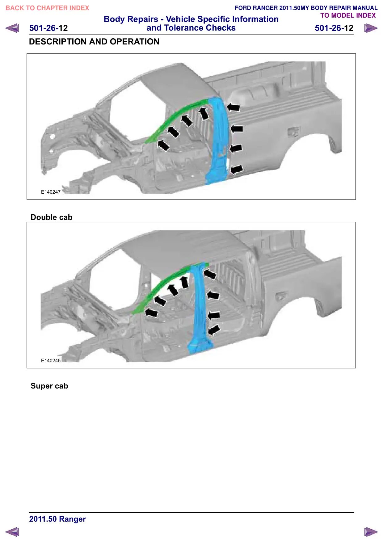
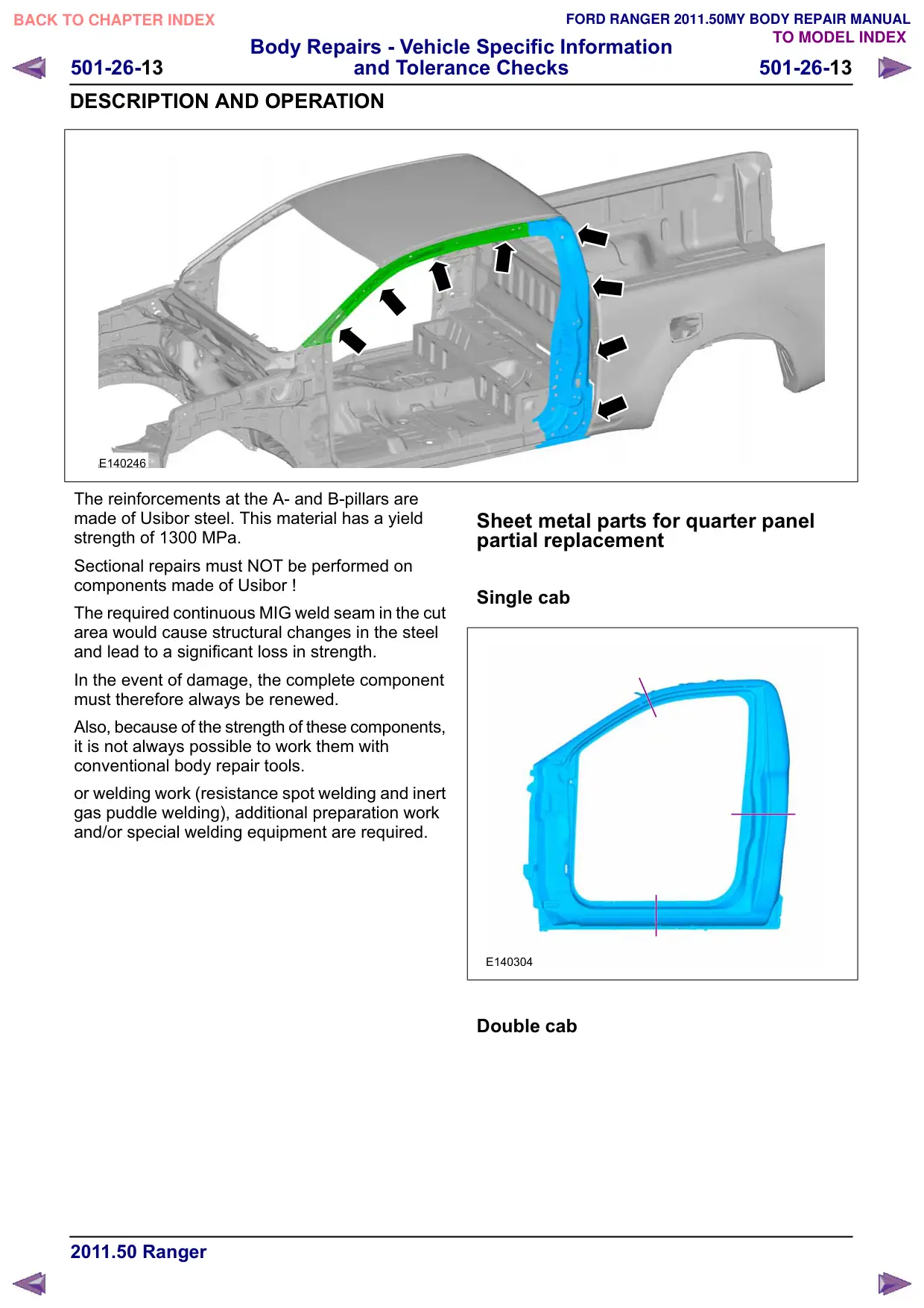
The reinforcements at the A- and B-pillars are
made of Usibor steel. This material has a yield
strength of 1300 MPa.
Sectional repairs must NOT be performed on
components made of Usibor !
The required continuous MIG weld seam in the cut
area would cause structural changes in the steel
and lead to a significant loss in strength.
In the event of damage, the complete component
must therefore always be renewed.
Also, because of the strength of these components,
it is not always possible to work them with
conventional body repair tools.
or welding work (resistance spot welding and inert
gas puddle welding), additional preparation work
and/or special welding equipment are required.
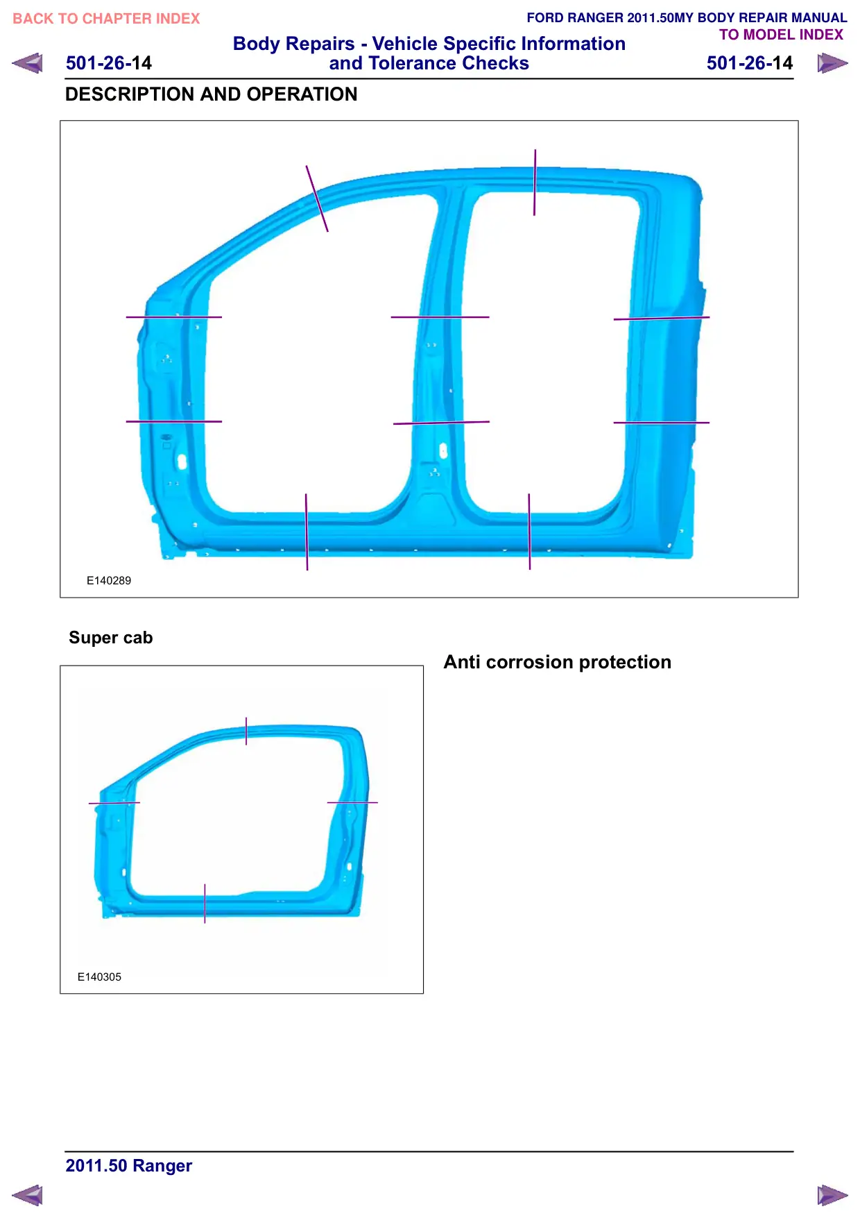
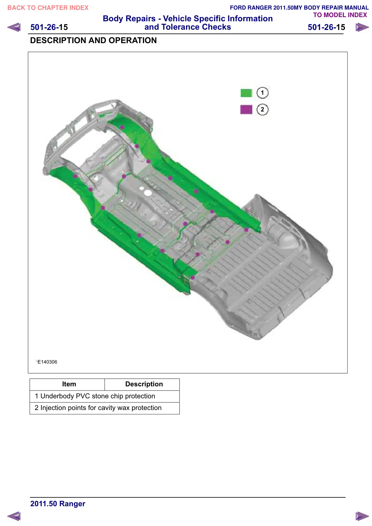
Sheet metal parts for quarter panel
partial replacement
Single cab
E140304
Double cab
Body Repairs - Vehicle Specific Information
501-26-14
and Tolerance Checks
501-26-14
DESCRIPTION AND OPERATION
E140289
Super cab
E140305
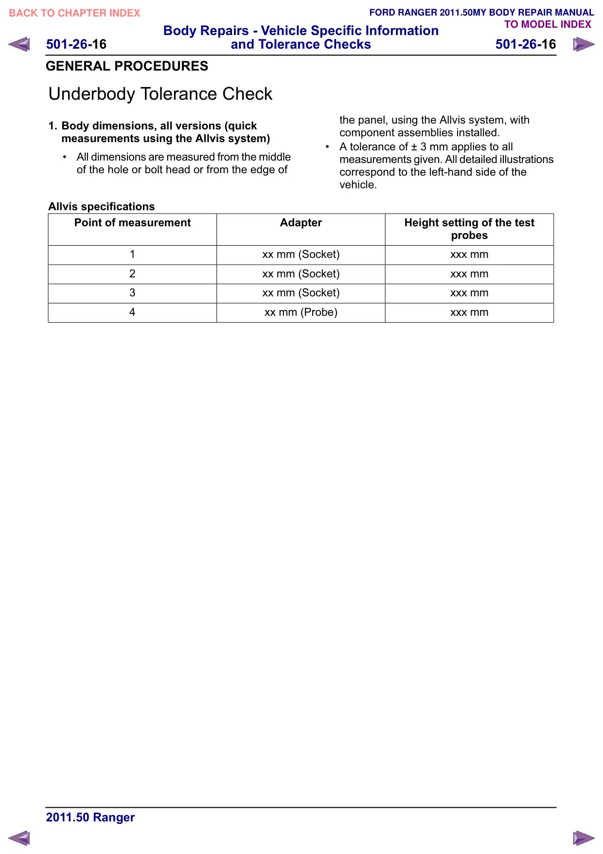
Anti corrosion protection
Body Repairs - Vehicle Specific Information
501-26-15
and Tolerance Checks
501-26-15
DESCRIPTION AND OPERATION
E140306
Item
Description
1 Underbody PVC stone chip protection
2 Injection points for cavity wax protection
1
2
Body Repairs - Vehicle Specific Information
501-26-16
and Tolerance Checks
501-26-16
GENERAL PROCEDURES
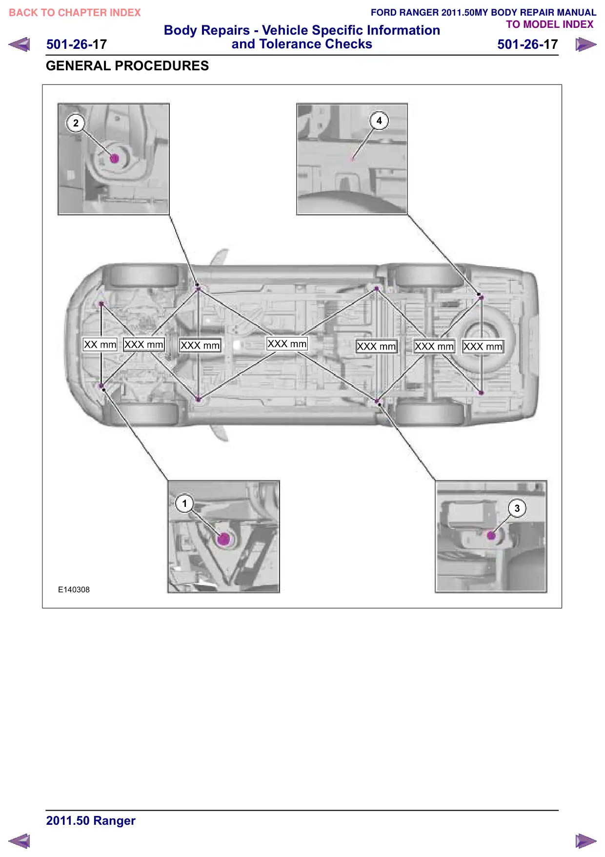
Underbody Tolerance Check
1. Body dimensions, all versions (quick
measurements using the Allvis system)
All dimensions are measured from the middle
of the hole or bolt head or from the edge of
Allvis specifications
Point of measurement
Adapter
1
xx mm (Socket)
2
xx mm (Socket)
3
xx mm (Socket)
4
xx mm (Probe)
the panel, using the Allvis system, with
component assemblies installed.
A tolerance of ± 3 mm applies to all
measurements given. All detailed illustrations
correspond to the left-hand side of the
vehicle.
Height setting of the test
probes
xxx mm
xxx mm
xxx mm
xxx mm
Body Repairs - Vehicle Specific Information
501-26-18
and Tolerance Checks
501-26-18
GENERAL PROCEDURES
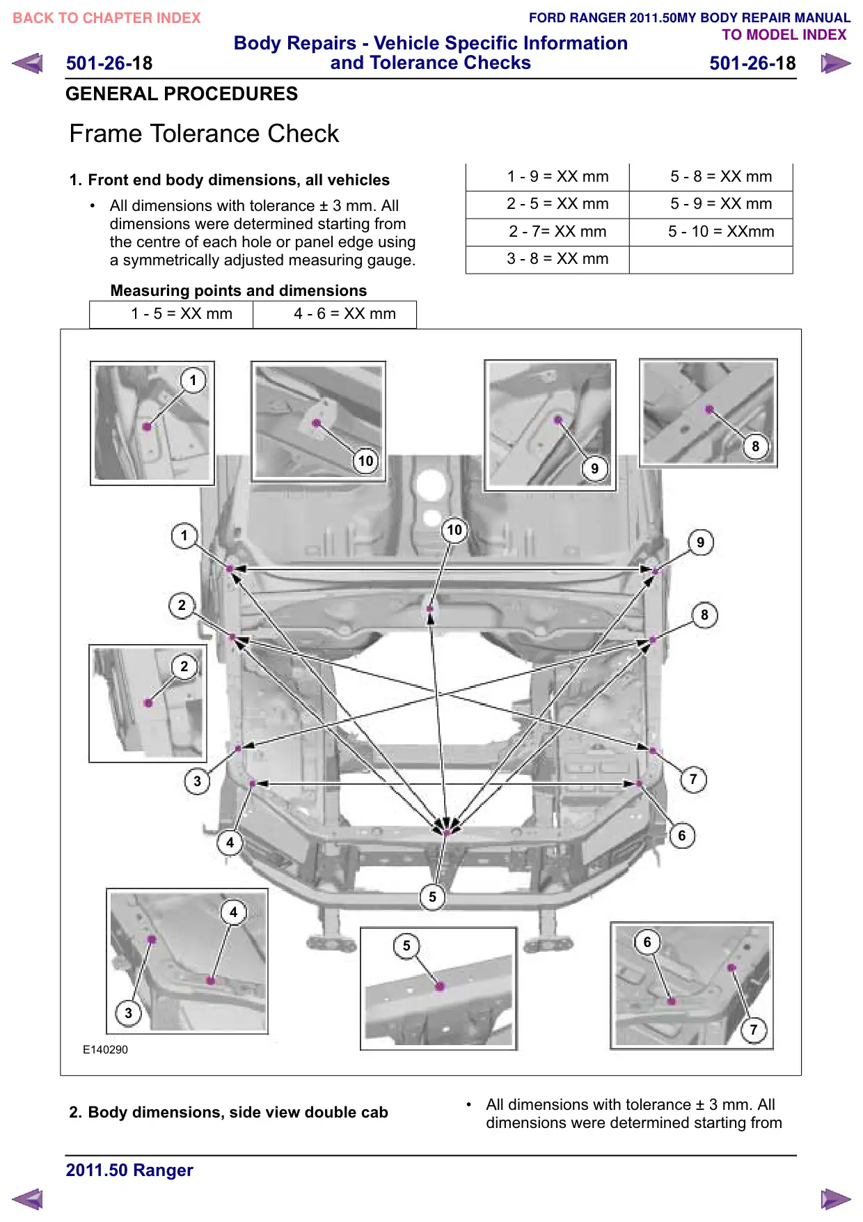
Frame Tolerance Check
1. Front end body dimensions, all vehicles
All dimensions with tolerance ± 3 mm. All
dimensions were determined starting from
the centre of each hole or panel edge using
a symmetrically adjusted measuring gauge.
Measuring points and dimensions
1 - 5 XX mm
4 - 6 XX mm
1
10
1
2
2
3
4
4
3
E140290
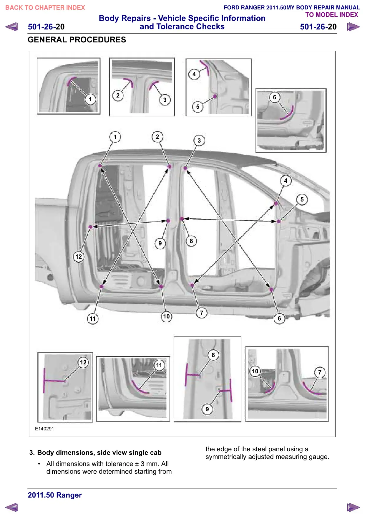
2. Body dimensions, side view double cab
1 - 9 XX mm
5 - 8 XX mm
2 - 5 XX mm
5 - 9 XX mm
2 - 7 XX mm
5 - 10 XXmm
3 - 8 XX mm
8
10
8
7
6
5
6
5
7
All dimensions with tolerance ± 3 mm. All
dimensions were determined starting from
Body Repairs - Vehicle Specific Information
501-26-19
and Tolerance Checks
501-26-19
GENERAL PROCEDURES
the edge of the steel panel using a
symmetrically adjusted measuring gauge.
Measuring points 1, 2, 3, 4, 6, 7, 10 and 11
are measured in the curve and represent the
greatest distance to the measuring point
opposite.
The detailed views of measuring points 8, 9
and 12 are shown looking from the vehicle
interior outwards.
The detailed view of measuring point 5 is
measured in the hole and represent the
greatest distance to the measuring point
opposite.
Measuring points and dimensions
1 - 10 XX mm
4 - 7 XX mm
2 - 11 XX mm
5 - 8 XX mm
3 - 6 XX mm
9 - 12 XX mm
Body Repairs - Vehicle Specific Information
501-26-20
and Tolerance Checks
501-26-20
GENERAL PROCEDURES
2
1
3
1
2
12
10
11
12
11
E140291
3. Body dimensions, side view single cab
All dimensions with tolerance ± 3 mm. All
dimensions were determined starting from
4
6
5
3
4
5
8
7
6
8
10
7
the edge of the steel panel using a
symmetrically adjusted measuring gauge.
Body Repairs - Vehicle Specific Information
501-26-21
and Tolerance Checks
501-26-21
GENERAL PROCEDURES
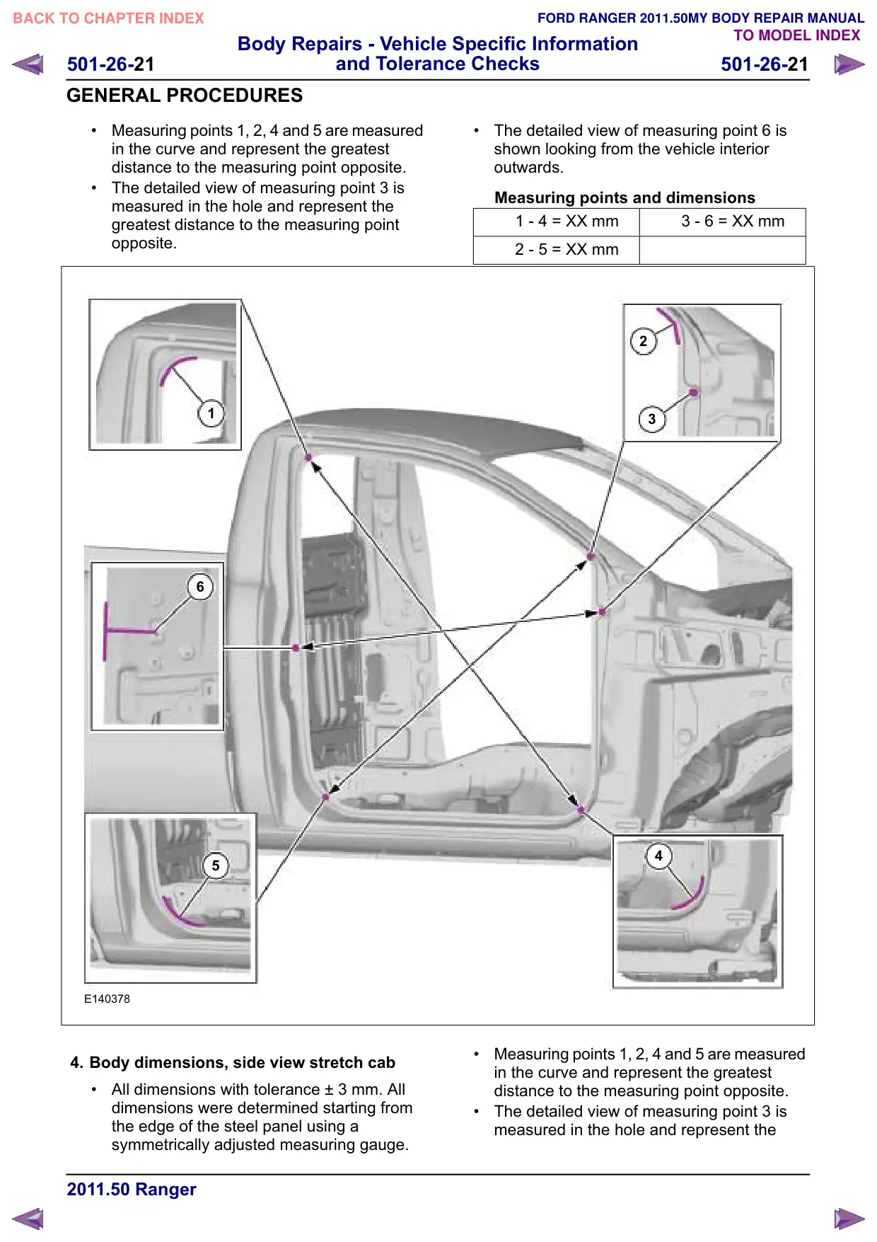
Measuring points 1, 2, 4 and 5 are measured
in the curve and represent the greatest
distance to the measuring point opposite.
The detailed view of measuring point 3 is
measured in the hole and represent the
greatest distance to the measuring point
opposite.
1
6
5
E140378
4. Body dimensions, side view stretch cab
All dimensions with tolerance ± 3 mm. All
dimensions were determined starting from
the edge of the steel panel using a
symmetrically adjusted measuring gauge.
The detailed view of measuring point 6 is
shown looking from the vehicle interior
outwards.
Measuring points and dimensions
1 - 4 XX mm
3 - 6 XX mm
2 - 5 XX mm
2
3
4
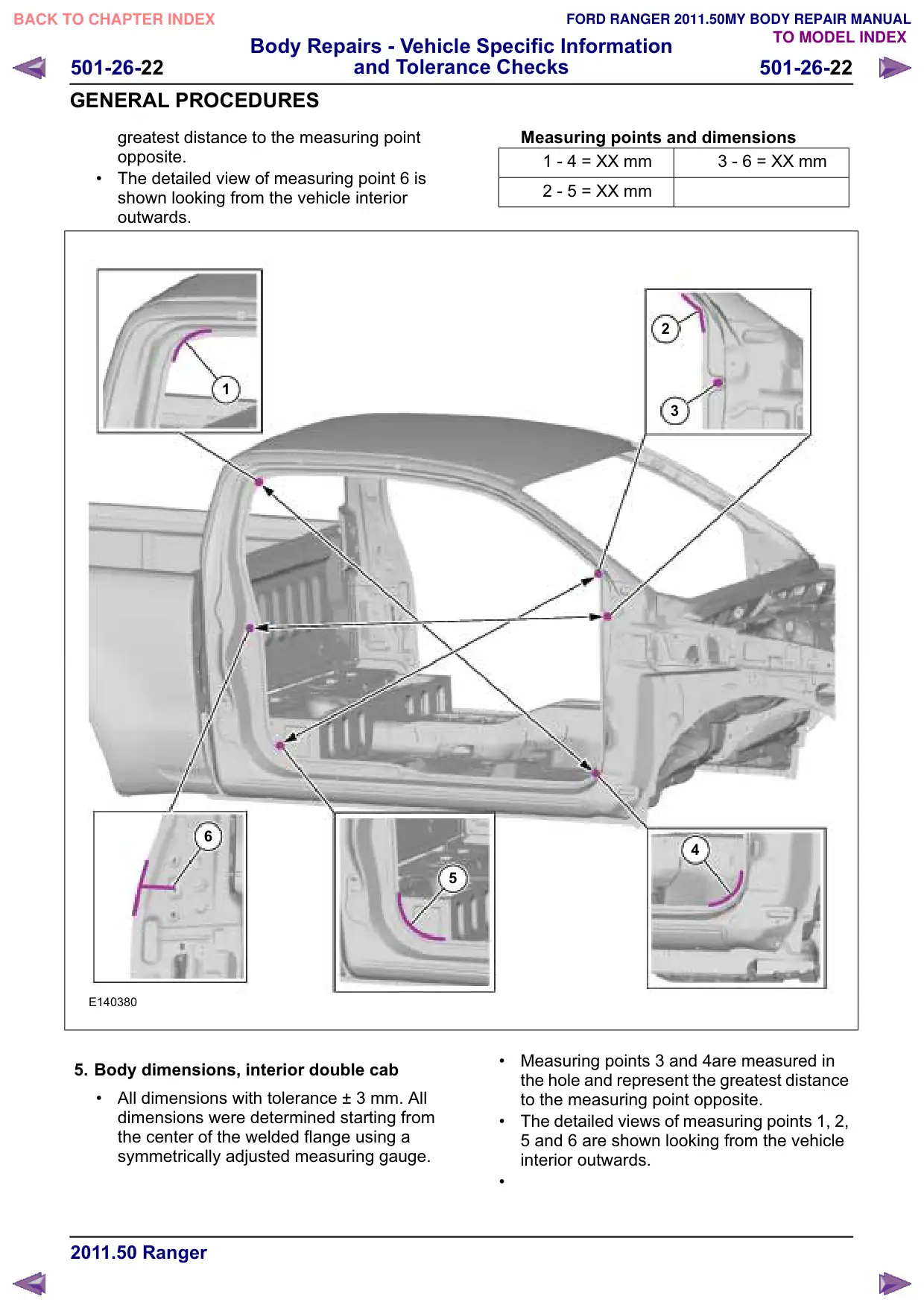
Measuring points 1, 2, 4 and 5 are measured
in the curve and represent the greatest
distance to the measuring point opposite.
The detailed view of measuring point 3 is
measured in the hole and represent the
Body Repairs - Vehicle Specific Information
501-26-22
and Tolerance Checks
501-26-22
GENERAL PROCEDURES
greatest distance to the measuring point
opposite.
The detailed view of measuring point 6 is
shown looking from the vehicle interior
outwards.
1
6
E140380
5. Body dimensions, interior double cab
All dimensions with tolerance ± 3 mm. All
dimensions were determined starting from
the center of the welded flange using a
symmetrically adjusted measuring gauge.
Measuring points and dimensions
1 - 4 XX mm
3 - 6 XX mm
2 - 5 XX mm
2
3
4
5
Measuring points 3 and 4are measured in
the hole and represent the greatest distance
to the measuring point opposite.
The detailed views of measuring points 1, 2,
5 and 6 are shown looking from the vehicle
interior outwards.
Body Repairs - Vehicle Specific Information
501-26-23
and Tolerance Checks
501-26-23
GENERAL PROCEDURES
Measuring points and dimensions
1 - 6 XX mm
3 - 4 XX mm
1
5
6
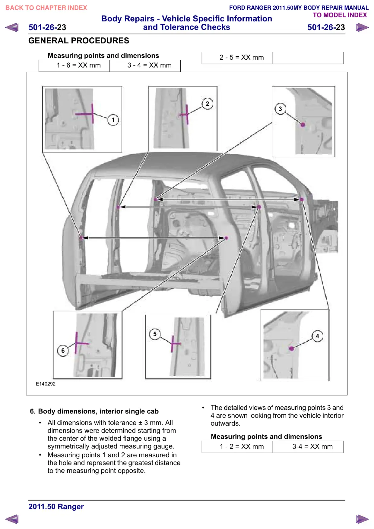
E140292
6. Body dimensions, interior single cab
All dimensions with tolerance ± 3 mm. All
dimensions were determined starting from
the center of the welded flange using a
symmetrically adjusted measuring gauge.
Measuring points 1 and 2 are measured in
the hole and represent the greatest distance
to the measuring point opposite.
2 - 5 XX mm
2
3
4
The detailed views of measuring points 3 and
4 are shown looking from the vehicle interior
outwards.
Measuring points and dimensions
1 - 2 XX mm
3-4 XX mm
Body Repairs - Vehicle Specific Information
501-26-24
and Tolerance Checks
501-26-24
GENERAL PROCEDURES
1
4
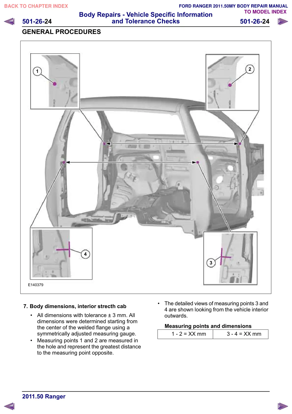
E140379
7. Body dimensions, interior strecth cab
All dimensions with tolerance ± 3 mm. All
dimensions were determined starting from
the center of the welded flange using a
symmetrically adjusted measuring gauge.
Measuring points 1 and 2 are measured in
the hole and represent the greatest distance
to the measuring point opposite.
2
3
The detailed views of measuring points 3 and
4 are shown looking from the vehicle interior
outwards.
Measuring points and dimensions
1 - 2 XX mm
3 - 4 XX mm
Body Repairs - Vehicle Specific Information
501-26-25
and Tolerance Checks
501-26-25
GENERAL PROCEDURES
1
4
E140381
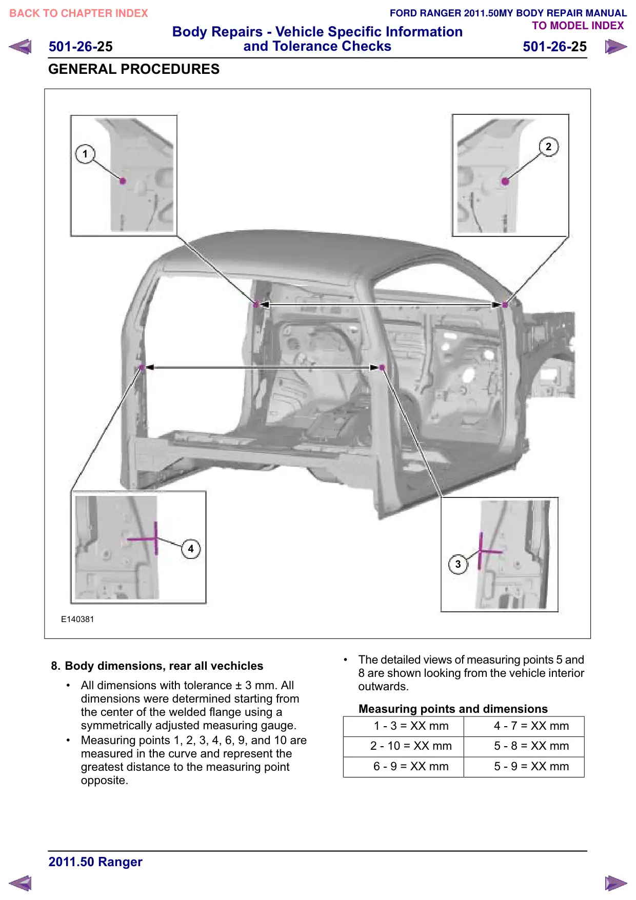
8. Body dimensions, rear all vechicles
All dimensions with tolerance ± 3 mm. All
dimensions were determined starting from
the center of the welded flange using a
symmetrically adjusted measuring gauge.
Measuring points 1, 2, 3, 4, 6, 9, and 10 are
measured in the curve and represent the
greatest distance to the measuring point
opposite.
2
3
The detailed views of measuring points 5 and
8 are shown looking from the vehicle interior
outwards.
Measuring points and dimensions
1 - 3 XX mm
4 - 7 XX mm
2 - 10 XX mm
5 - 8 XX mm
6 - 9 XX mm
5 - 9 XX mm
Body Repairs - Vehicle Specific Information
501-26-26
and Tolerance Checks
501-26-26
GENERAL PROCEDURES
1
2
10
3
1
10
8
7
7
8
E140293
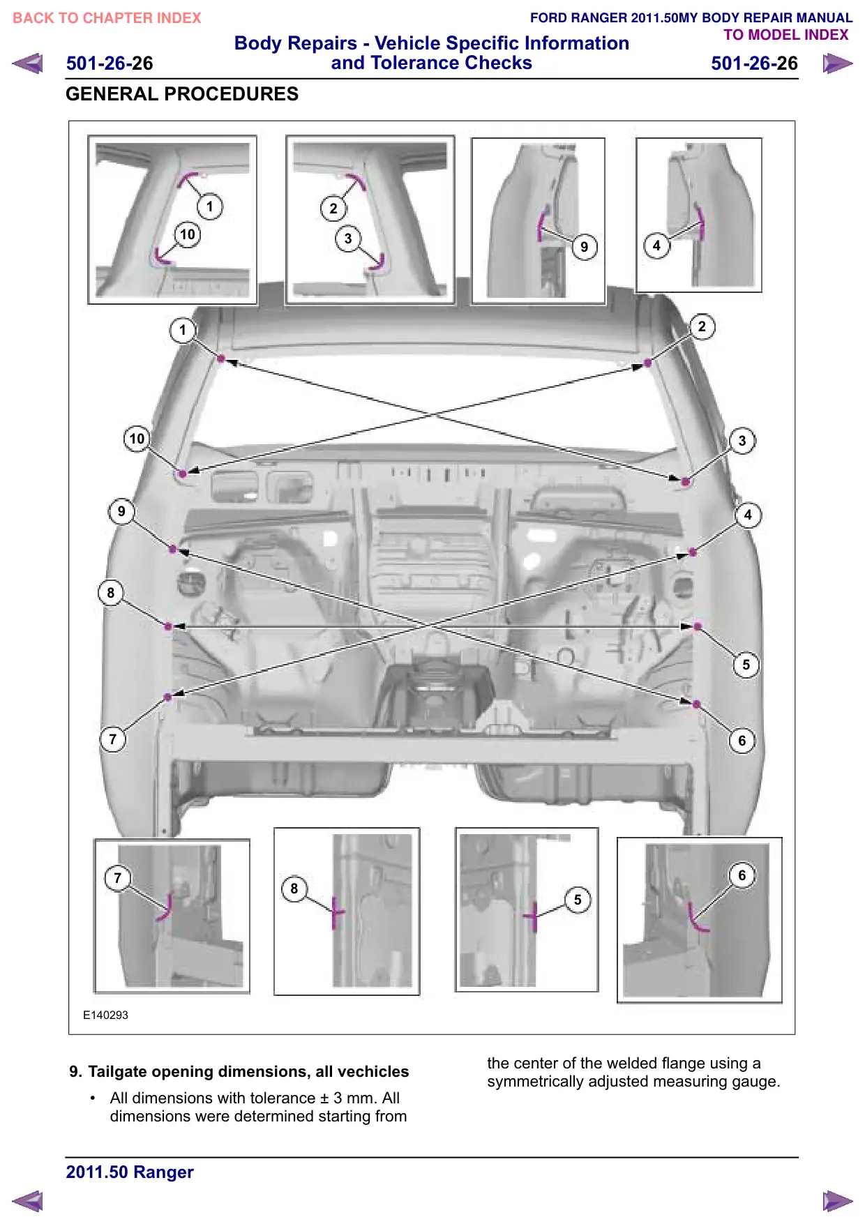
9. Tailgate opening dimensions, all vechicles
All dimensions with tolerance ± 3 mm. All
dimensions were determined starting from
4
2
3
4
5
6
6
5
the center of the welded flange using a
symmetrically adjusted measuring gauge.
Body Repairs - Vehicle Specific Information
501-26-27
and Tolerance Checks
501-26-27
GENERAL PROCEDURES
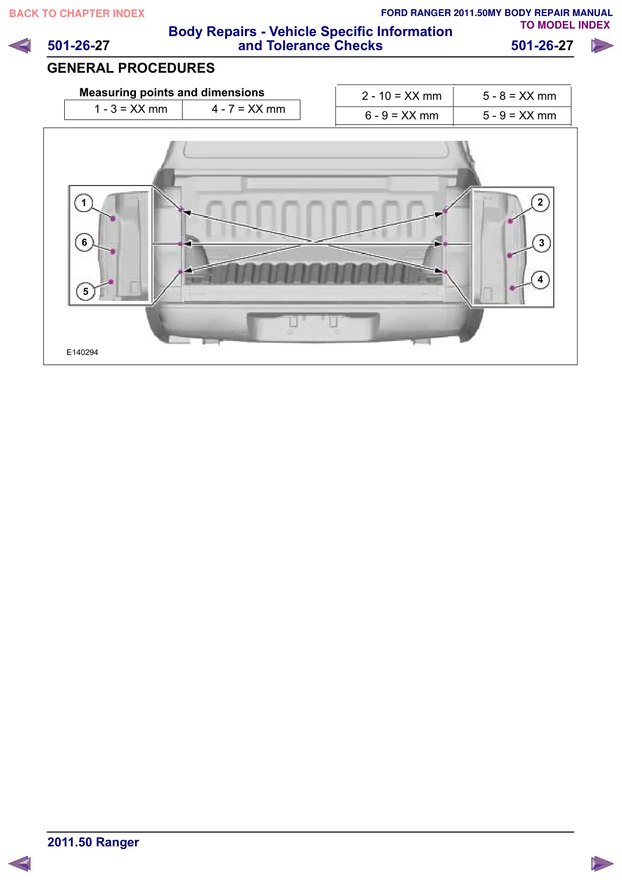
Measuring points and dimensions
1 - 3 XX mm
4 - 7 XX mm
1
6
5
E140294
2 - 10 XX mm
5 - 8 XX mm
6 - 9 XX mm
5 - 9 XX mm
2
3
4