Verificação de tolerâncias do chassi
Frame Tolerance Check
Texto da página
Link desta página: https://ranger.mbrace.com.br/carroceria/373
Imagem: https://ranger.mbrace.com.br/img/carroceria/373.webp
Body Repairs - Vehicle Specific Information
501-26-21
and Tolerance Checks
501-26-21
GENERAL PROCEDURES
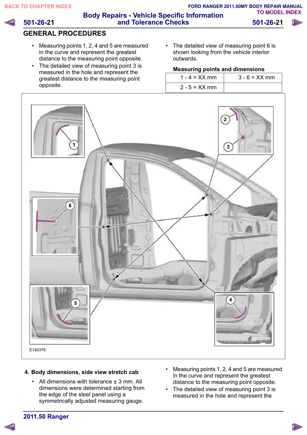
Measuring points 1, 2, 4 and 5 are measured
in the curve and represent the greatest
distance to the measuring point opposite.
The detailed view of measuring point 3 is
measured in the hole and represent the
greatest distance to the measuring point
opposite.
1
6
5
E140378
4. Body dimensions, side view stretch cab
All dimensions with tolerance ± 3 mm. All
dimensions were determined starting from
the edge of the steel panel using a
symmetrically adjusted measuring gauge.
The detailed view of measuring point 6 is
shown looking from the vehicle interior
outwards.
Measuring points and dimensions
1 - 4 XX mm
3 - 6 XX mm
2 - 5 XX mm
2
3
4
Measuring points 1, 2, 4 and 5 are measured
in the curve and represent the greatest
distance to the measuring point opposite.
The detailed view of measuring point 3 is
measured in the hole and represent the