Busca

501-12 Painel e console

Carroceria · páginas 125–155

Texto completo da seção, página por página. Toque no título para ver a página com a imagem.

  1. Índice da seção p. 125
  2. Painel p. 126
  3. Painel – LHD 4WD/LHD RWD p. 127–134
  4. Painel – RHD 4WD/RHD RWD p. 135–142
  5. Console central – Cabine simples p. 143–144
  6. Console central – Cabine dupla p. 145–147
  7. Travessa interna do veículo p. 148
  8. Porta-luvas p. 149
  9. Console do teto p. 150–151
  10. Painel p. 152–155

Página 125 · Índice da seção

Contents

501-12-1 Instrument Panel and Console 501-12-1 . SECTION 501-12 Instrument Panel and Console VEHICLE APPLICATION: 2011.50 Ranger CONTENTS DESCRIPTION AND OPERATION Instrument Panel................................................................................................................. REMOVAL AND INSTALLATION Instrument Panel – LHD 4WD/LHD RWD......................................................................... Instrument Panel – RHD 4WD/RHD RWD........................................................................ Floor Console – Single Cab.............................................................................................. Floor Console – Double Cab............................................................................................. In-Vehicle Crossbeam......................................................................................................... Glove Compartment............................................................................................................ Overhead Console.............................................................................................................. DISASSEMBLY AND ASSEMBLY Instrument Panel................................................................................................................. PAGE 501-12-2 501-12-3 501-12-11 501-12-19 501-12-21 501-12-24 501-12-25 501-12-26 501-12-28

Página 126 · Painel

Instrument Panel

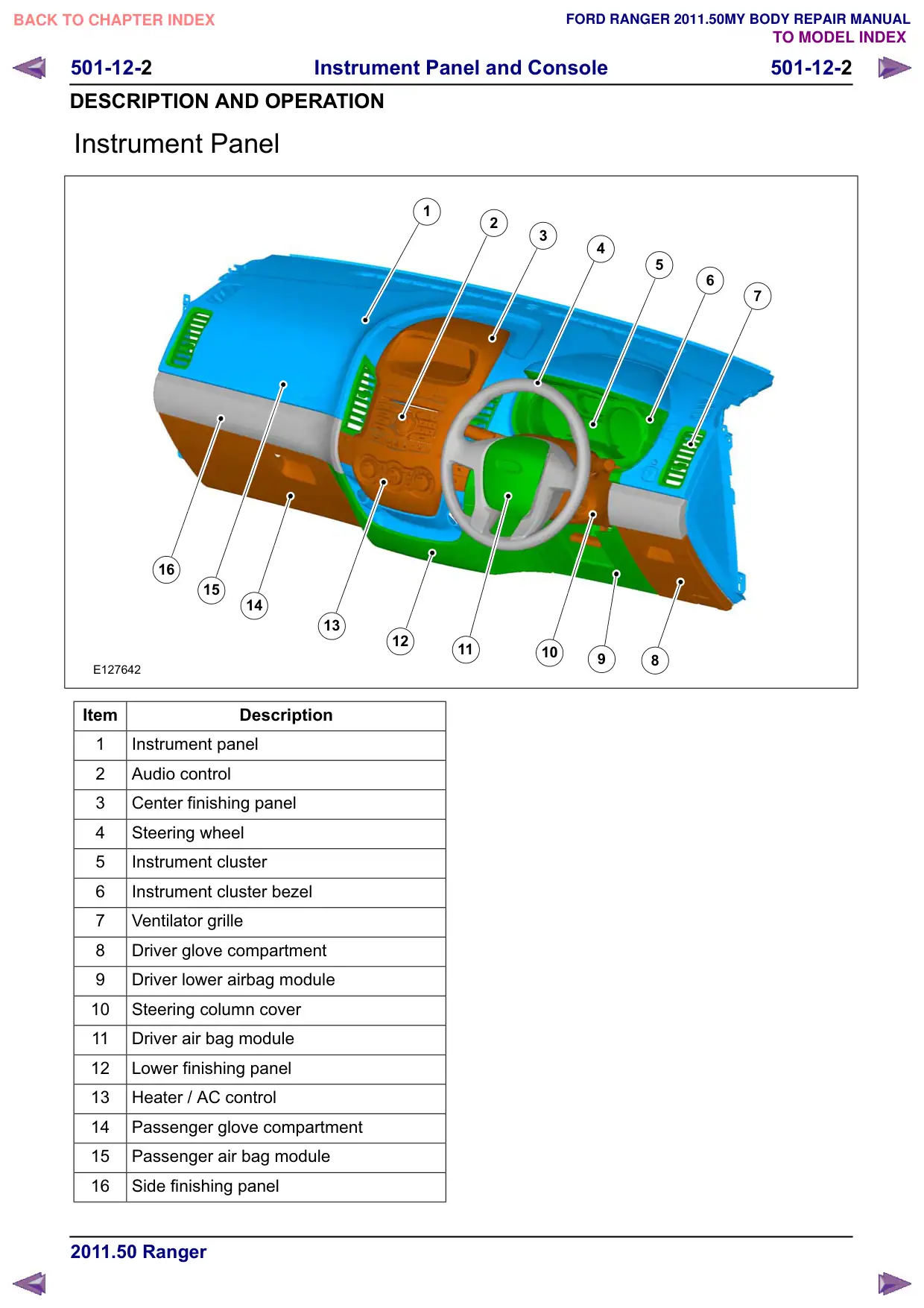
501-12-2 Instrument Panel and Console 501-12-2 DESCRIPTION AND OPERATION Instrument Panel 1 16 15 14 13 12 E127642 Item Description 1 Instrument panel 2 Audio control 3 Center finishing panel 4 Steering wheel 5 Instrument cluster 6 Instrument cluster bezel 7 Ventilator grille 8 Driver glove compartment Driver lower airbag module 10 Steering column cover 11 Driver air bag module 12 Lower finishing panel 13 Heater / AC control 14 Passenger glove compartment 15 Passenger air bag module 16 Side finishing panel 2 3 4 5 6 7 11 10 8

Página 127 · Painel – LHD 4WD/LHD RWD

Instrument Panel – LHD 4WD/LHD RWD

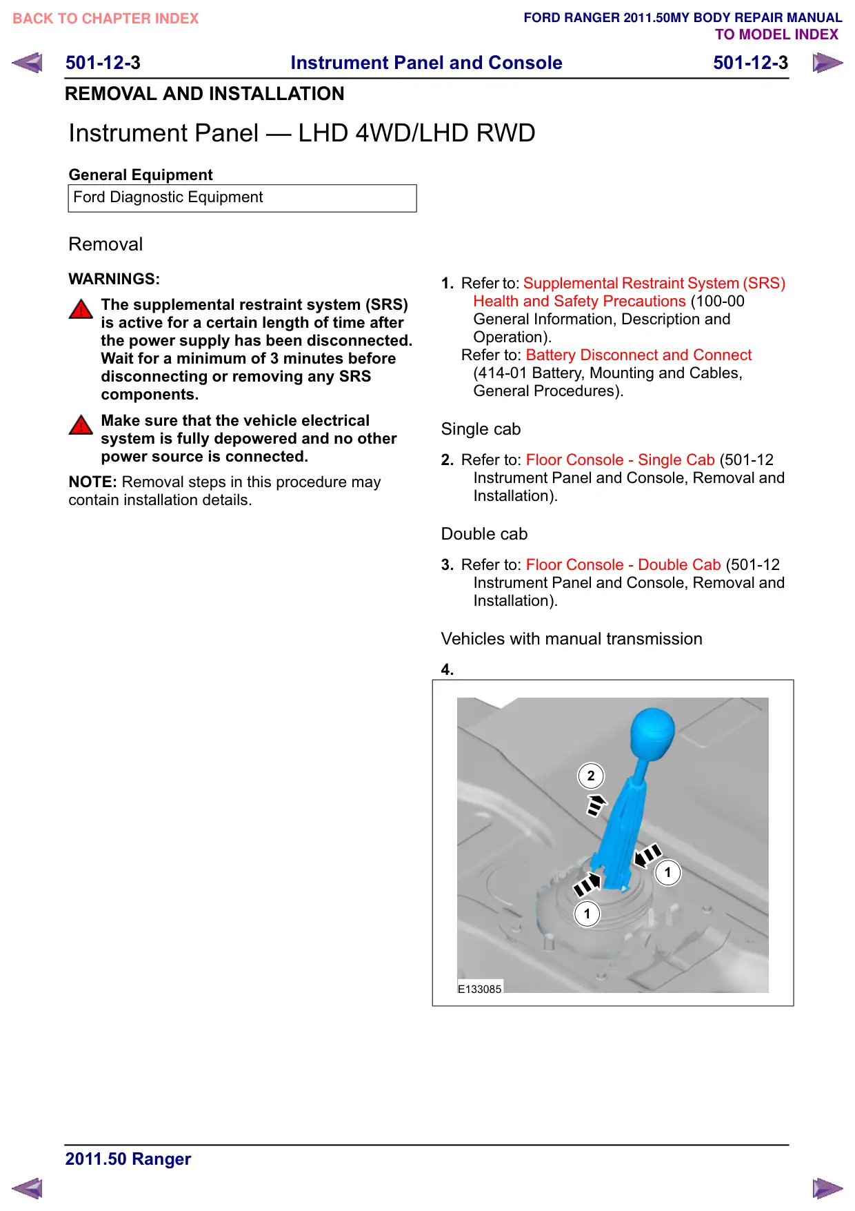
501-12-3 Instrument Panel and Console 501-12-3 REMOVAL AND INSTALLATION Instrument Panel – LHD 4WD/LHD RWD General Equipment Ford Diagnostic Equipment Removal WARNINGS: The supplemental restraint system (SRS) is active for a certain length of time after the power supply has been disconnected. Wait for a minimum of 3 minutes before disconnecting or removing any SRS components. Make sure that the vehicle electrical system is fully depowered and no other power source is connected. NOTE: Removal steps in this procedure may contain installation details. 1. Refer to: Supplemental Restraint System (SRS) Health and Safety Precautions (100-00 General Information, Description and Operation). Refer to: Battery Disconnect and Connect (414-01 Battery, Mounting and Cables, General Procedures). Single cab 2. Refer to: Floor Console - Single Cab (501-12 Instrument Panel and Console, Removal and Installation). Double cab 3. Refer to: Floor Console - Double Cab (501-12 Instrument Panel and Console, Removal and Installation). Vehicles with manual transmission 4. 2 1 1 E133085

Página 128 · Painel – LHD 4WD/LHD RWD

Instrument Panel – LHD 4WD/LHD RWD

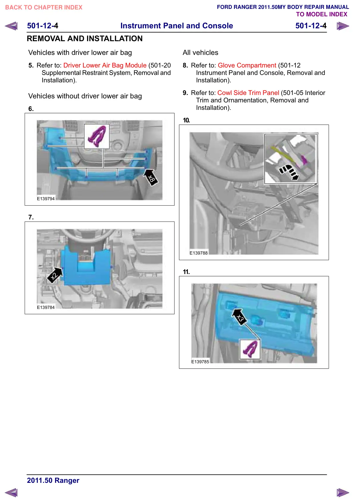
Instrument Panel and Console 501-12-4 501-12-4 REMOVAL AND INSTALLATION Vehicles with driver lower air bag 5. Refer to: Driver Lower Air Bag Module (501-20 Supplemental Restraint System, Removal and Installation). Vehicles without driver lower air bag 6. x8 E139794 7. x2 E139784 All vehicles 8. Refer to: Glove Compartment (501-12 Instrument Panel and Console, Removal and Installation). 9. Refer to: Cowl Side Trim Panel (501-05 Interior Trim and Ornamentation, Removal and Installation). 10. E139788 11. x3 E139785

Página 129 · Painel – LHD 4WD/LHD RWD

Instrument Panel – LHD 4WD/LHD RWD

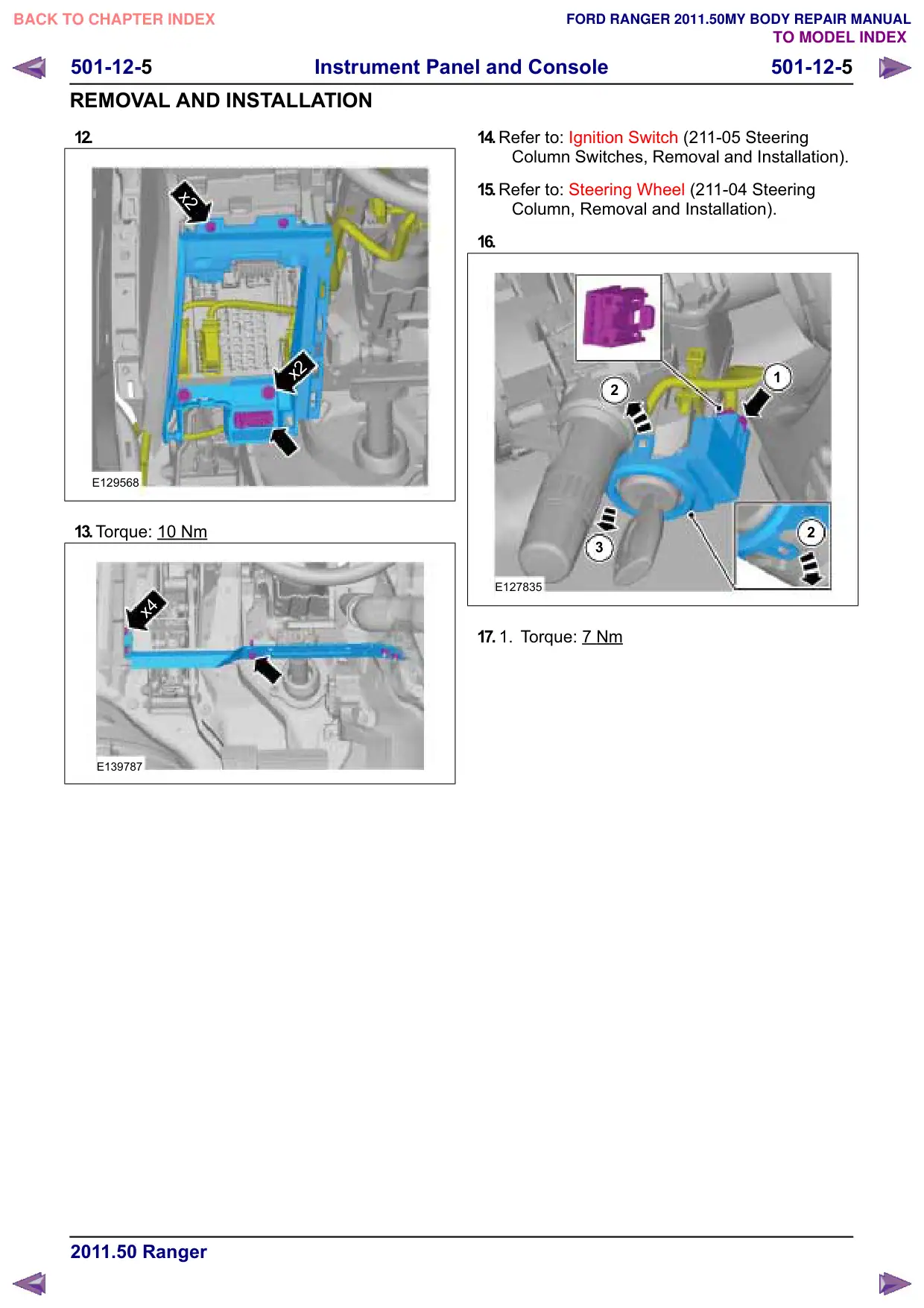
Instrument Panel and Console 501-12-5 501-12-5 REMOVAL AND INSTALLATION 12. x2 x2 E129568 13.Torque: 10 Nm x4 E139787 14.Refer to: Ignition Switch (211-05 Steering Column Switches, Removal and Installation). 15.Refer to: Steering Wheel (211-04 Steering Column, Removal and Installation). 16. 1 2 2 3 E127835 17. 1. Torque: 7 Nm

Página 130 · Painel – LHD 4WD/LHD RWD

Instrument Panel – LHD 4WD/LHD RWD

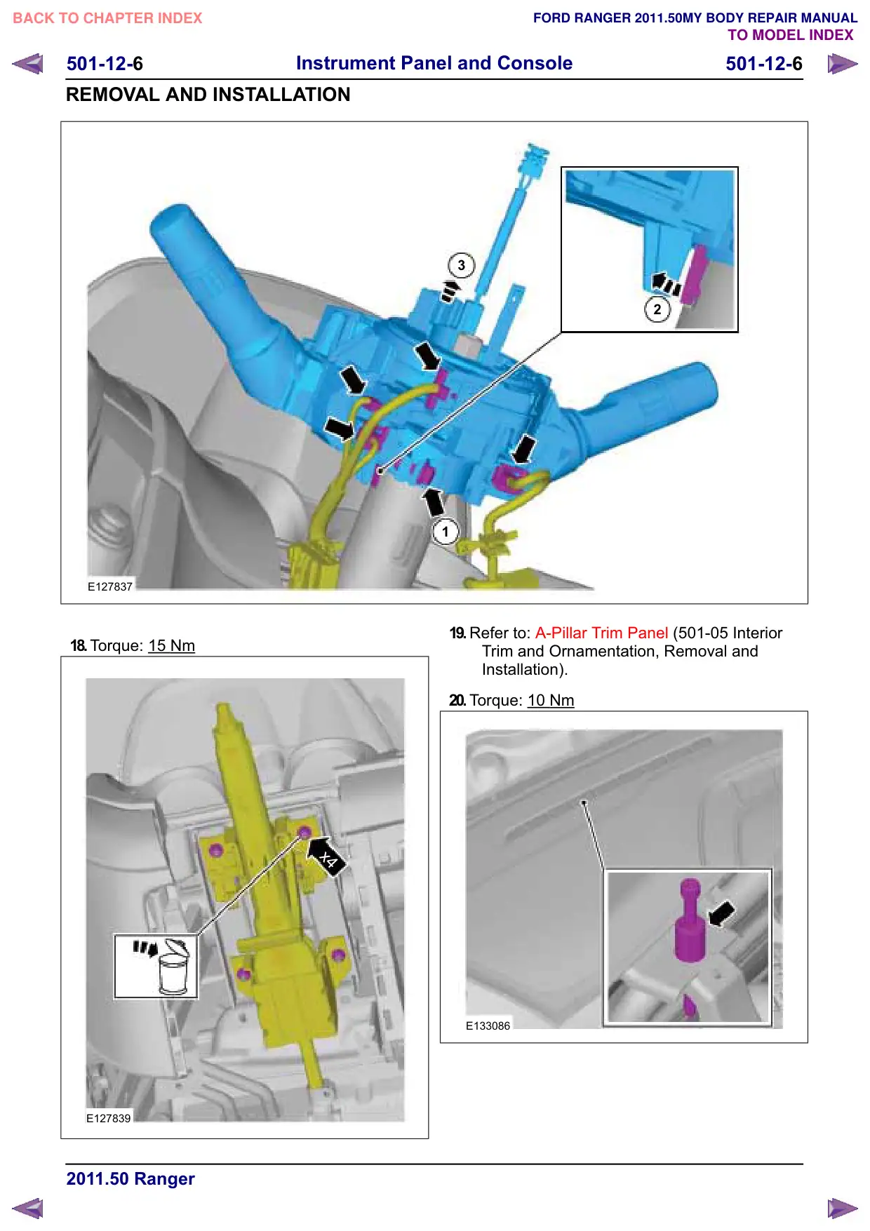
501-12-6 Instrument Panel and Console 501-12-6 REMOVAL AND INSTALLATION E127837 18.Torque: 15 Nm x4 E127839 3 2 1 19.Refer to: A-Pillar Trim Panel (501-05 Interior Trim and Ornamentation, Removal and Installation). 20.Torque: 10 Nm E133086

Página 131 · Painel – LHD 4WD/LHD RWD

Instrument Panel – LHD 4WD/LHD RWD

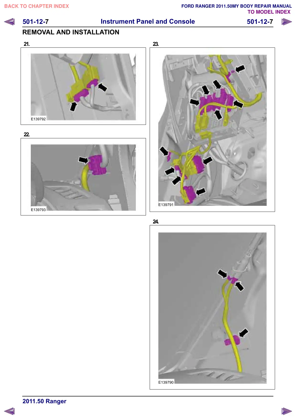
501-12-7 Instrument Panel and Console 501-12-7 REMOVAL AND INSTALLATION 21. E139792 22. E139793 23. E139791 24. E139790

Página 132 · Painel – LHD 4WD/LHD RWD

Instrument Panel – LHD 4WD/LHD RWD

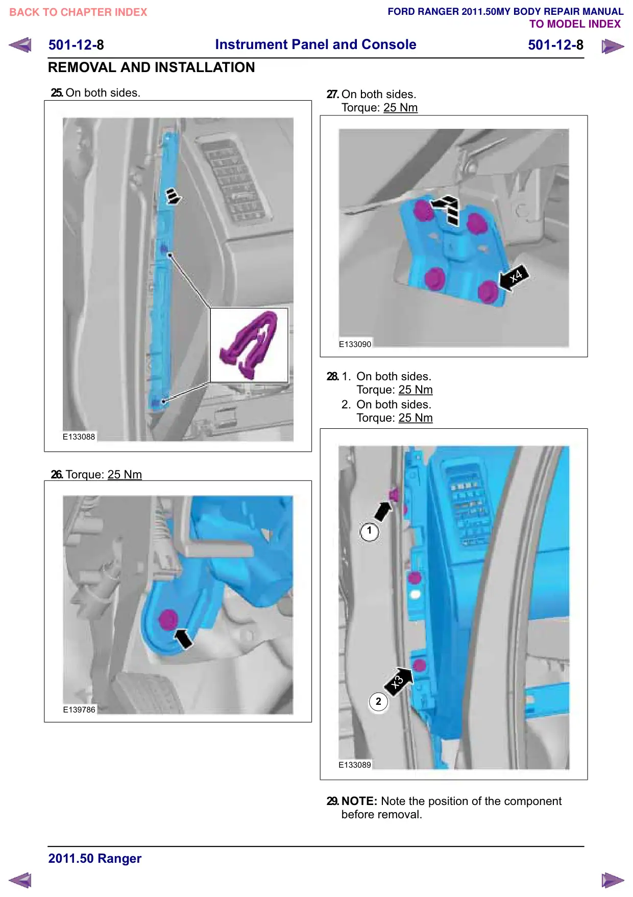
501-12-8 Instrument Panel and Console 501-12-8 REMOVAL AND INSTALLATION 25.On both sides. E133088 26.Torque: 25 Nm E139786 27.On both sides. Torque: 25 Nm x4 E133090 28. 1. On both sides. Torque: 25 Nm 2. On both sides. Torque: 25 Nm 1 x3 2 E133089 29.NOTE: Note the position of the component before removal.

Página 133 · Painel – LHD 4WD/LHD RWD

Instrument Panel – LHD 4WD/LHD RWD

501-12- Instrument Panel and Console 501-12- REMOVAL AND INSTALLATION E139789 Installation 1. CAUTION: Make sure that the three locking positions are locked correctely. NOTE: Make sure that the adjuster is correctely alighned.

Página 134 · Painel – LHD 4WD/LHD RWD

Instrument Panel – LHD 4WD/LHD RWD

501-12-10 Instrument Panel and Console 501-12-10 REMOVAL AND INSTALLATION E139789 2. To install, reverse the removal procedure. 3. Configure the steering column module. General Equipment: Ford Diagnostic Equipment

Página 135 · Painel – RHD 4WD/RHD RWD

Instrument Panel – RHD 4WD/RHD RWD

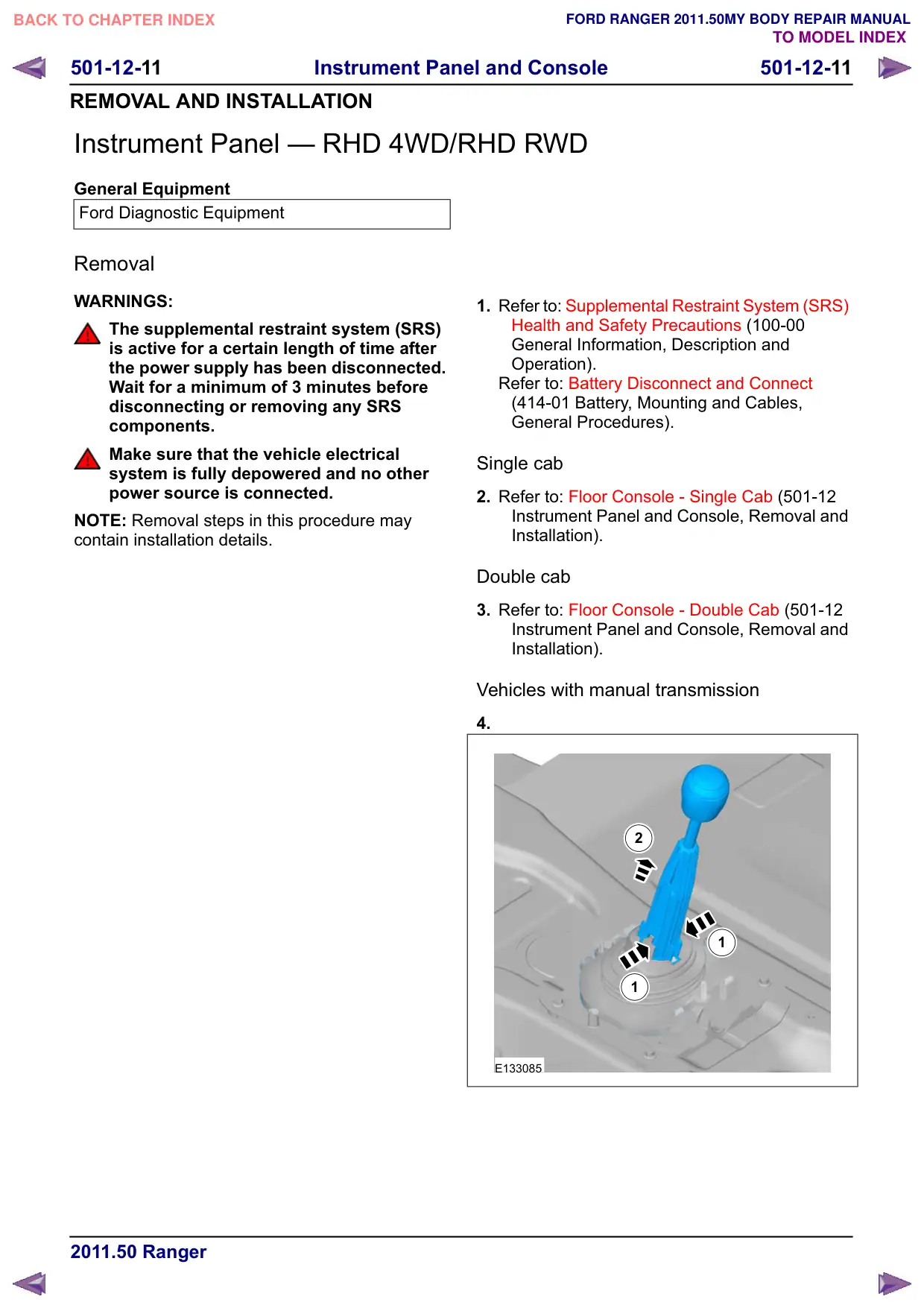
501-12-11 Instrument Panel and Console 501-12-11 REMOVAL AND INSTALLATION Instrument Panel – RHD 4WD/RHD RWD General Equipment Ford Diagnostic Equipment Removal WARNINGS: The supplemental restraint system (SRS) is active for a certain length of time after the power supply has been disconnected. Wait for a minimum of 3 minutes before disconnecting or removing any SRS components. Make sure that the vehicle electrical system is fully depowered and no other power source is connected. NOTE: Removal steps in this procedure may contain installation details. 1. Refer to: Supplemental Restraint System (SRS) Health and Safety Precautions (100-00 General Information, Description and Operation). Refer to: Battery Disconnect and Connect (414-01 Battery, Mounting and Cables, General Procedures). Single cab 2. Refer to: Floor Console - Single Cab (501-12 Instrument Panel and Console, Removal and Installation). Double cab 3. Refer to: Floor Console - Double Cab (501-12 Instrument Panel and Console, Removal and Installation). Vehicles with manual transmission 4. 2 1 1 E133085

Página 136 · Painel – RHD 4WD/RHD RWD

Instrument Panel – RHD 4WD/RHD RWD

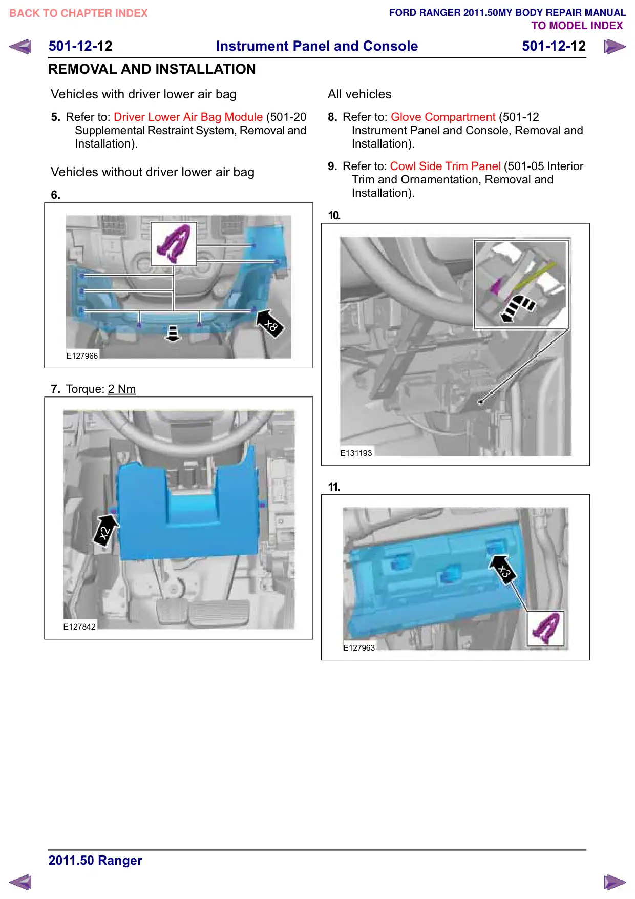
Instrument Panel and Console 501-12-12 501-12-12 REMOVAL AND INSTALLATION Vehicles with driver lower air bag 5. Refer to: Driver Lower Air Bag Module (501-20 Supplemental Restraint System, Removal and Installation). Vehicles without driver lower air bag 6. x8 E127966 7. Torque: 2 Nm x2 E127842 All vehicles 8. Refer to: Glove Compartment (501-12 Instrument Panel and Console, Removal and Installation). 9. Refer to: Cowl Side Trim Panel (501-05 Interior Trim and Ornamentation, Removal and Installation). 10. E131193 11. x3 E127963

Página 137 · Painel – RHD 4WD/RHD RWD

Instrument Panel – RHD 4WD/RHD RWD

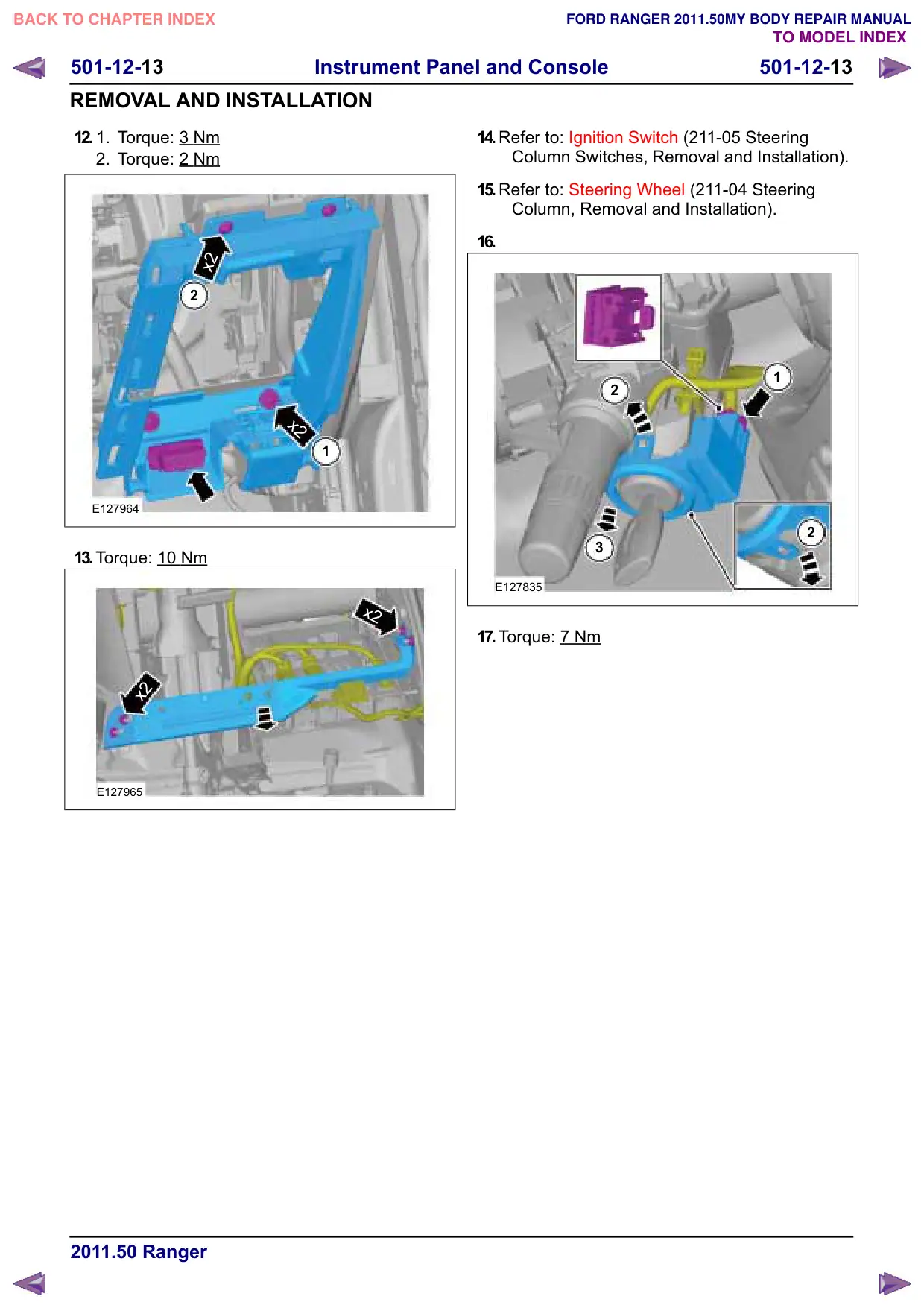
Instrument Panel and Console 501-12-13 501-12-13 REMOVAL AND INSTALLATION 12. 1. Torque: 3 Nm 2. Torque: 2 Nm x2 2 x2 1 E127964 13.Torque: 10 Nm x2 x2 E127965 14.Refer to: Ignition Switch (211-05 Steering Column Switches, Removal and Installation). 15.Refer to: Steering Wheel (211-04 Steering Column, Removal and Installation). 16. 1 2 2 3 E127835 17.Torque: 7 Nm

Página 138 · Painel – RHD 4WD/RHD RWD

Instrument Panel – RHD 4WD/RHD RWD

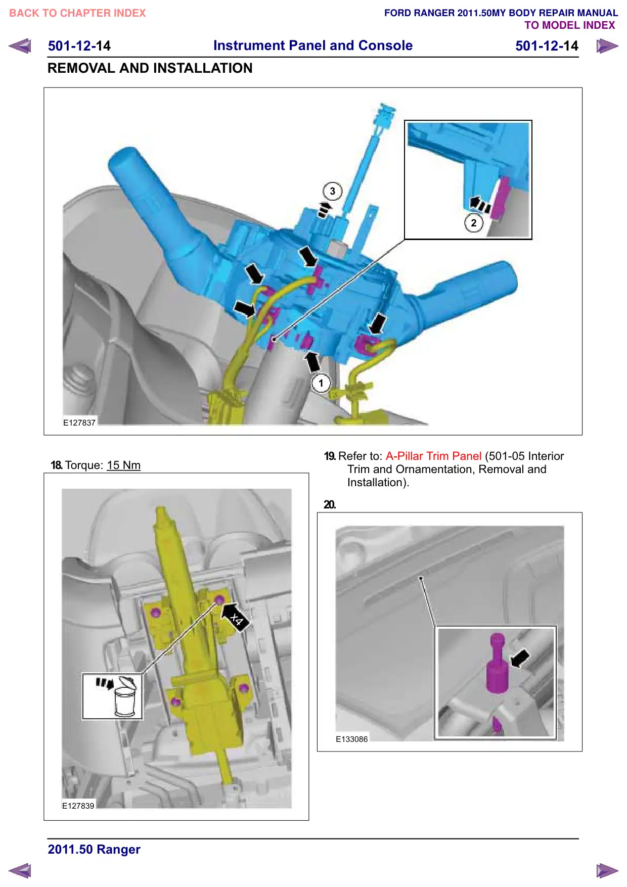
501-12-14 Instrument Panel and Console 501-12-14 REMOVAL AND INSTALLATION E127837 18.Torque: 15 Nm x4 E127839 3 2 1 19.Refer to: A-Pillar Trim Panel (501-05 Interior Trim and Ornamentation, Removal and Installation). 20. E133086

Página 139 · Painel – RHD 4WD/RHD RWD

Instrument Panel – RHD 4WD/RHD RWD

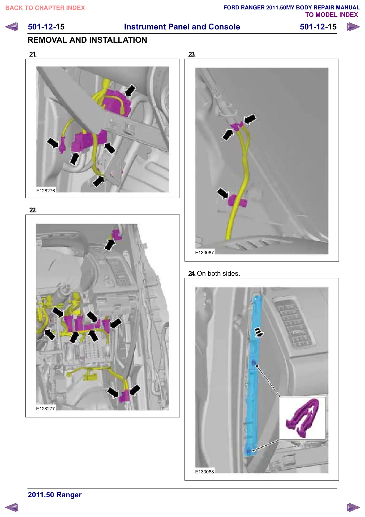
501-12-15 Instrument Panel and Console 501-12-15 REMOVAL AND INSTALLATION 21. E128276 22. E128277 23. E133087 24.On both sides. E133088

Página 140 · Painel – RHD 4WD/RHD RWD

Instrument Panel – RHD 4WD/RHD RWD

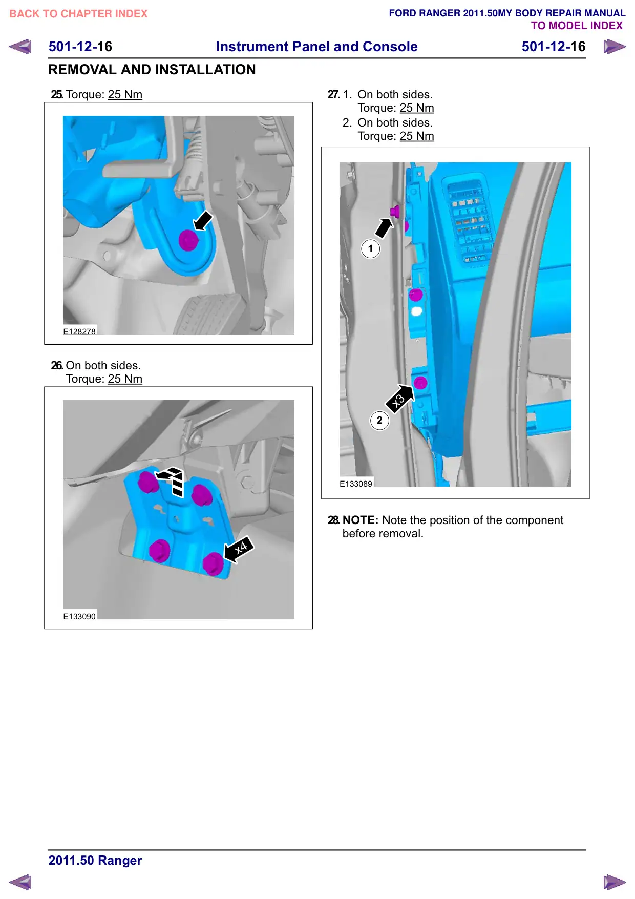
501-12-16 Instrument Panel and Console 501-12-16 REMOVAL AND INSTALLATION 25.Torque: 25 Nm E128278 26.On both sides. Torque: 25 Nm x4 E133090 27. 1. On both sides. Torque: 25 Nm 2. On both sides. Torque: 25 Nm 1 x3 2 E133089 28.NOTE: Note the position of the component before removal.

Página 141 · Painel – RHD 4WD/RHD RWD

Instrument Panel – RHD 4WD/RHD RWD

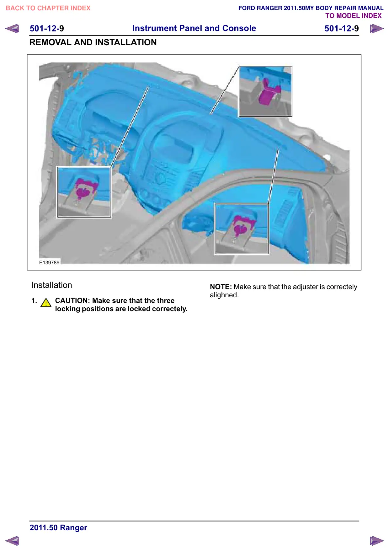
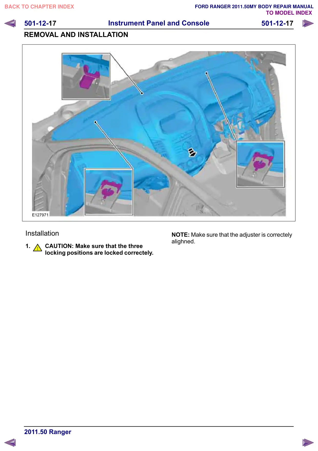
501-12-17 Instrument Panel and Console 501-12-17 REMOVAL AND INSTALLATION E127971 Installation 1. CAUTION: Make sure that the three locking positions are locked correctely. NOTE: Make sure that the adjuster is correctely alighned.

Página 142 · Painel – RHD 4WD/RHD RWD

Instrument Panel – RHD 4WD/RHD RWD

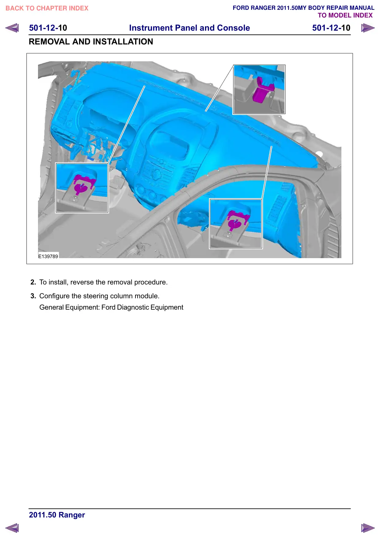
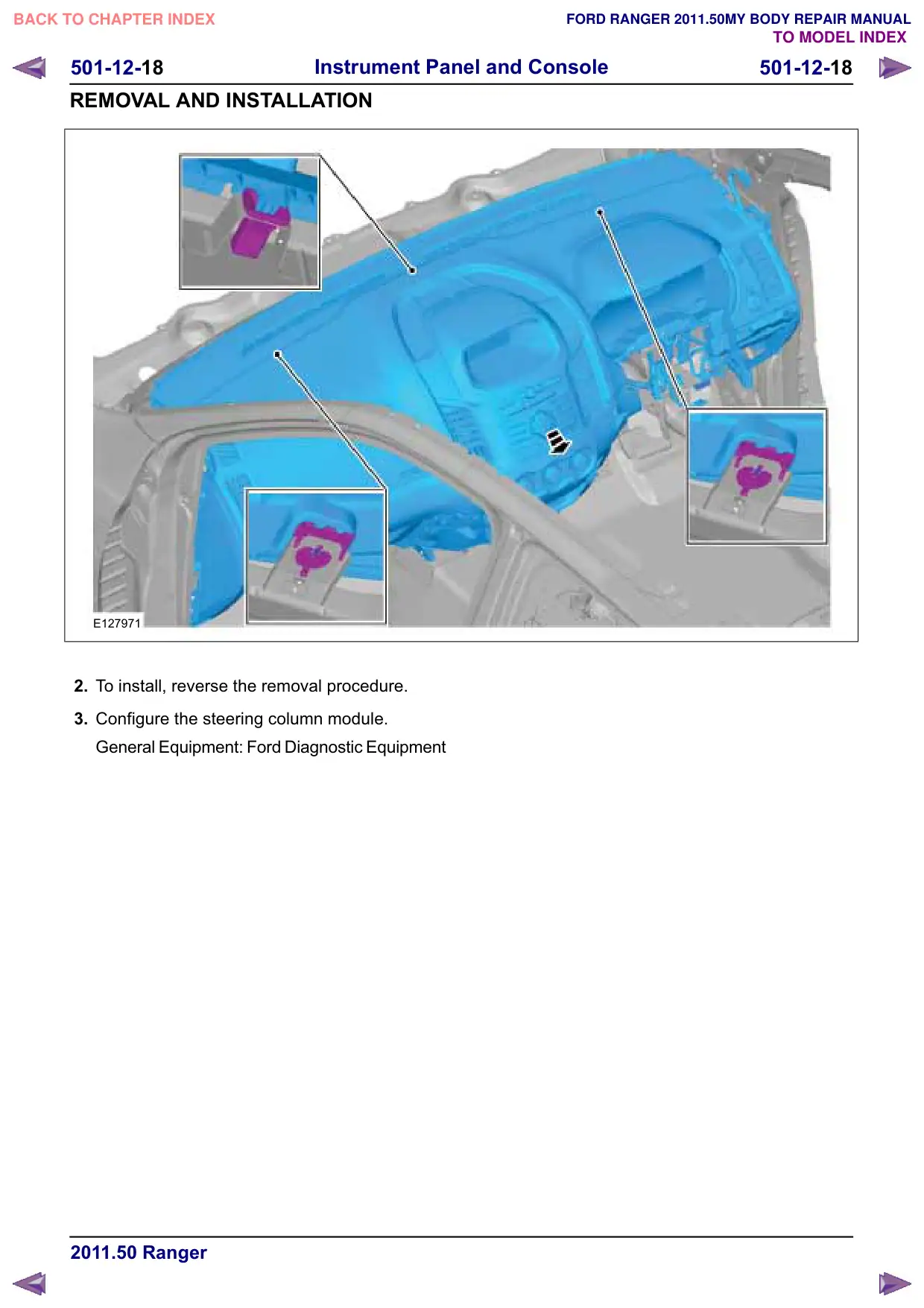
501-12-18 Instrument Panel and Console 501-12-18 REMOVAL AND INSTALLATION E127971 2. To install, reverse the removal procedure. 3. Configure the steering column module. General Equipment: Ford Diagnostic Equipment

Página 143 · Console central – Cabine simples

Floor Console – Single Cab

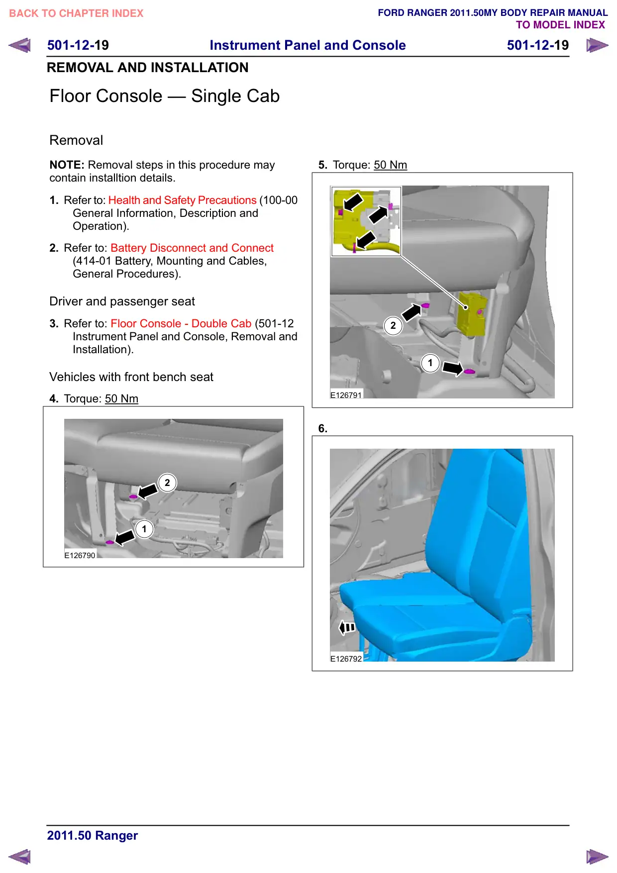
501-12-19 Instrument Panel and Console 501-12-19 REMOVAL AND INSTALLATION Floor Console – Single Cab Removal NOTE: Removal steps in this procedure may contain installtion details. 1. Refer to: Health and Safety Precautions (100-00 General Information, Description and Operation). 2. Refer to: Battery Disconnect and Connect (414-01 Battery, Mounting and Cables, General Procedures). Driver and passenger seat 3. Refer to: Floor Console - Double Cab (501-12 Instrument Panel and Console, Removal and Installation). Vehicles with front bench seat 4. Torque: 50 Nm 2 1 E126790 5. Torque: 50 Nm 2 1 E126791 6. E126792

Página 144 · Console central – Cabine simples

Floor Console – Single Cab

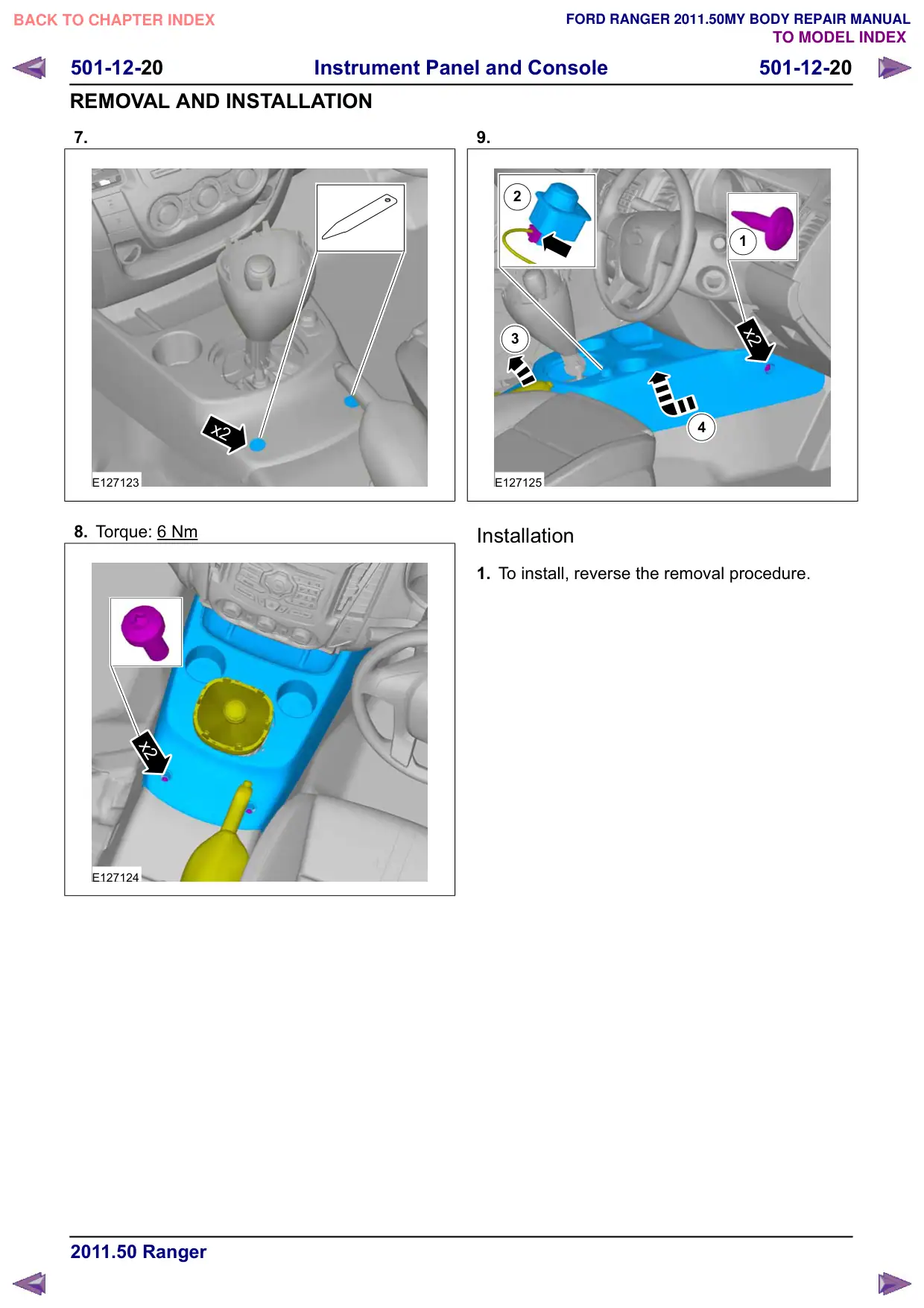
501-12-20 Instrument Panel and Console 501-12-20 REMOVAL AND INSTALLATION 7. x2 E127123 8. Torque: 6 Nm x2 E127124 9. 2 1 x2 3 4 E127125 Installation 1. To install, reverse the removal procedure.

Página 145 · Console central – Cabine dupla

Floor Console – Double Cab

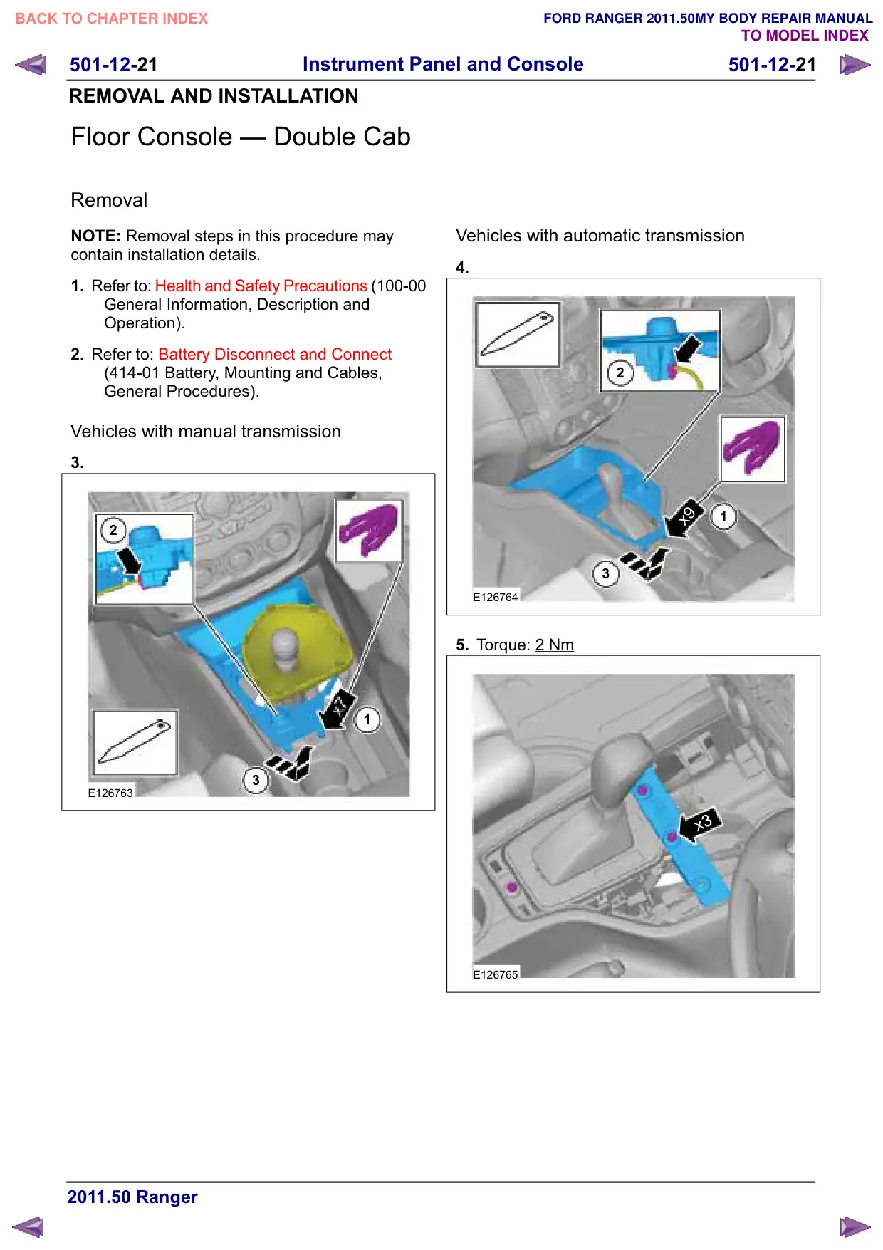
Instrument Panel and Console 501-12-21 501-12-21 REMOVAL AND INSTALLATION Floor Console – Double Cab Removal NOTE: Removal steps in this procedure may contain installation details. 1. Refer to: Health and Safety Precautions (100-00 General Information, Description and Operation). 2. Refer to: Battery Disconnect and Connect (414-01 Battery, Mounting and Cables, General Procedures). Vehicles with manual transmission 3. 2 1 3 E126763 Vehicles with automatic transmission 4. 2 x9 1 3 E126764 5. Torque: 2 Nm x3 E126765

Página 146 · Console central – Cabine dupla

Floor Console – Double Cab

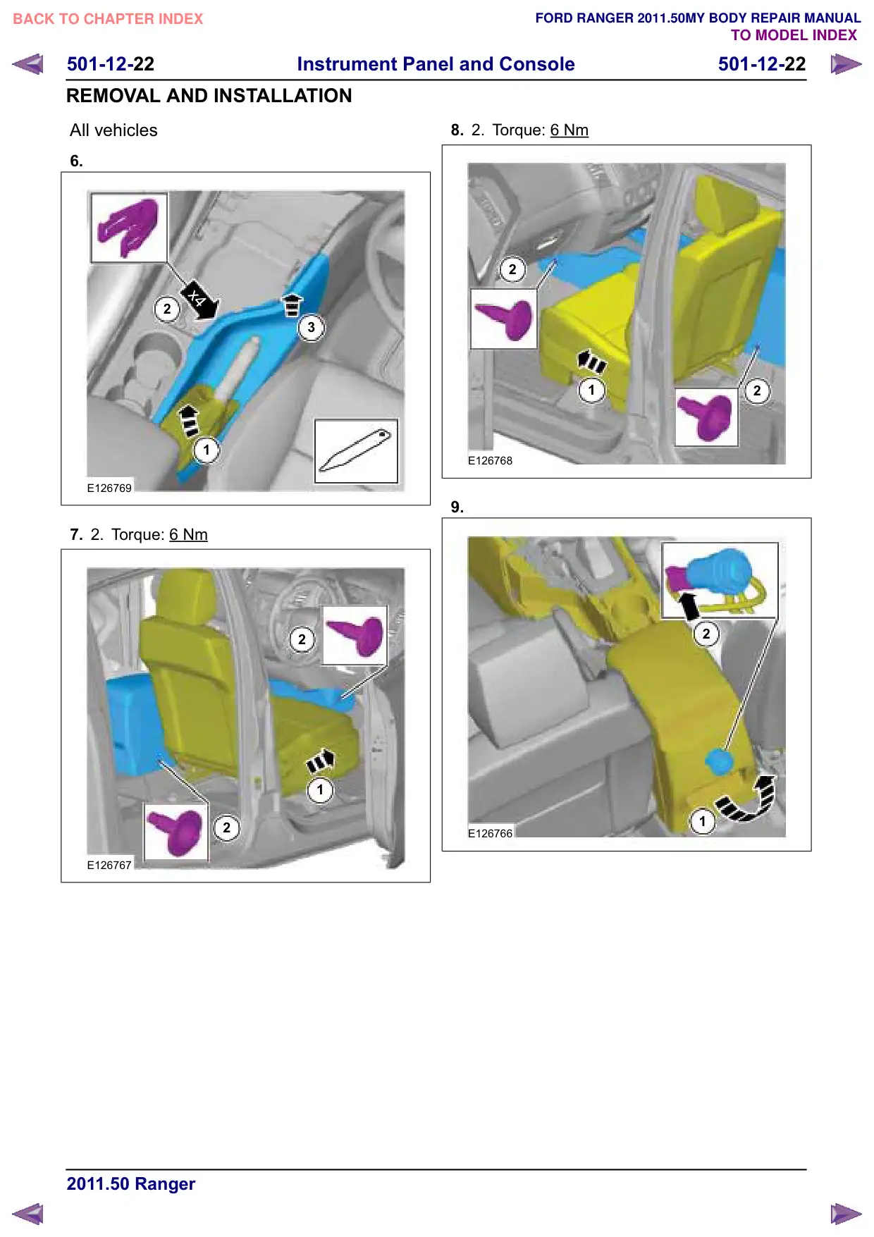
501-12-22 Instrument Panel and Console 501-12-22 REMOVAL AND INSTALLATION All vehicles 6. x4 2 3 1 E126769 7. 2. Torque: 6 Nm 2 1 2 E126767 8. 2. Torque: 6 Nm 2 1 2 E126768 9. 2 1 E126766

Página 147 · Console central – Cabine dupla

Floor Console – Double Cab

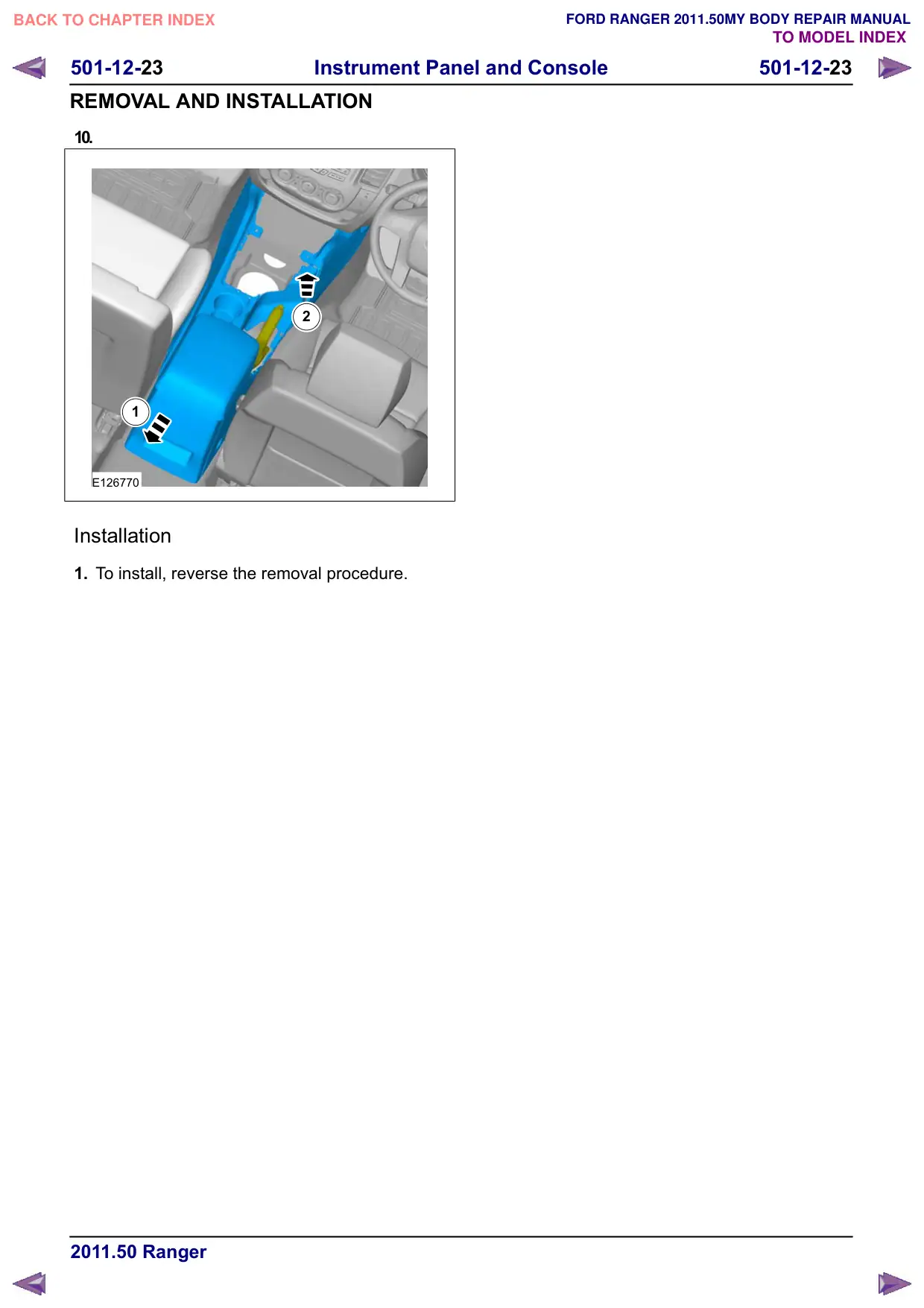
501-12-23 Instrument Panel and Console 501-12-23 REMOVAL AND INSTALLATION 10. 2 1 E126770 Installation 1. To install, reverse the removal procedure.

Página 148 · Travessa interna do veículo

In-Vehicle Crossbeam

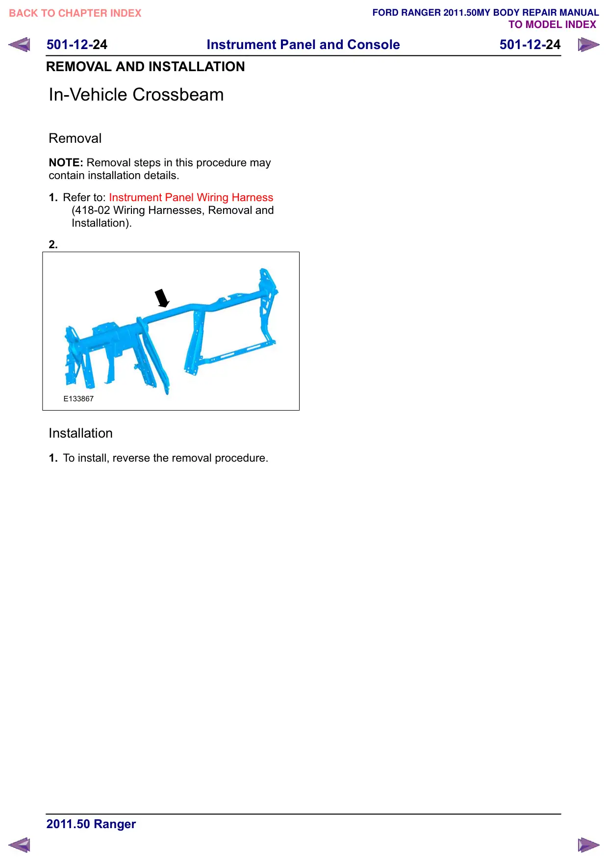
501-12-24 Instrument Panel and Console 501-12-24 REMOVAL AND INSTALLATION In-Vehicle Crossbeam Removal NOTE: Removal steps in this procedure may contain installation details. 1. Refer to: Instrument Panel Wiring Harness (418-02 Wiring Harnesses, Removal and Installation). 2. E133867 Installation 1. To install, reverse the removal procedure.

Página 149 · Porta-luvas

Glove Compartment

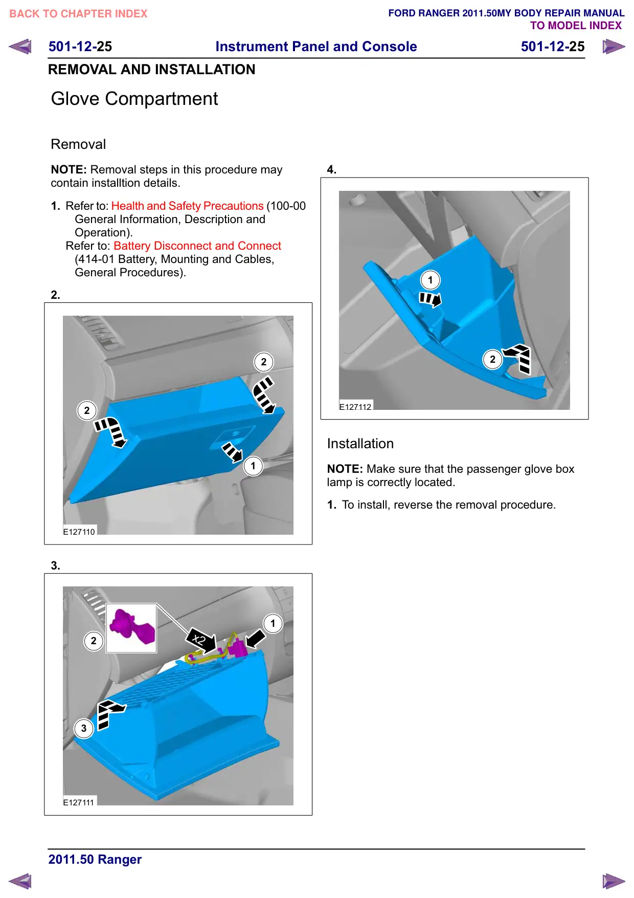
501-12-25 Instrument Panel and Console 501-12-25 REMOVAL AND INSTALLATION Glove Compartment Removal NOTE: Removal steps in this procedure may contain installtion details. 1. Refer to: Health and Safety Precautions (100-00 General Information, Description and Operation). Refer to: Battery Disconnect and Connect (414-01 Battery, Mounting and Cables, General Procedures). 2. 2 2 1 E127110 3. 1 x2 2 3 E127111 4. 1 2 E127112 Installation NOTE: Make sure that the passenger glove box lamp is correctly located. 1. To install, reverse the removal procedure.

Página 150 · Console do teto

Overhead Console

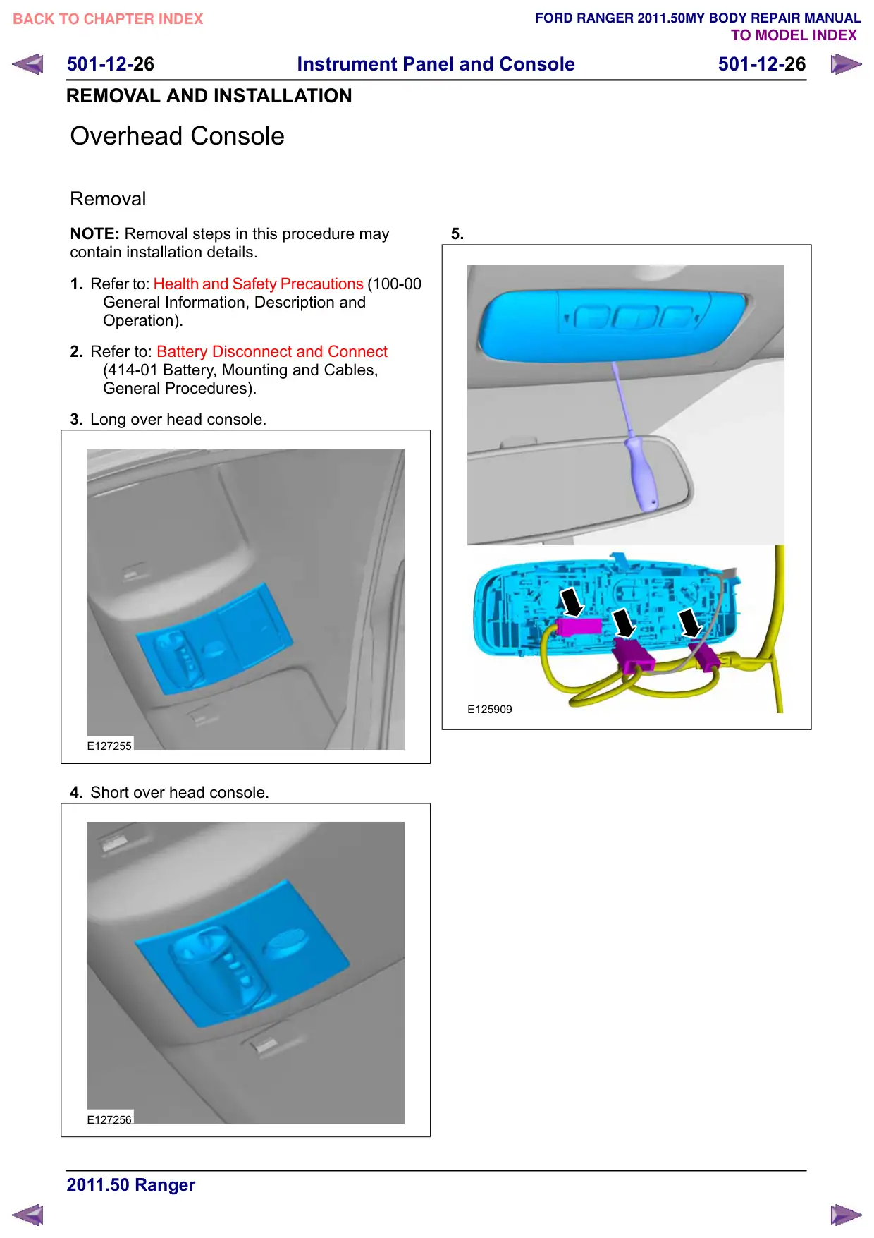
501-12-26 Instrument Panel and Console 501-12-26 REMOVAL AND INSTALLATION Overhead Console Removal NOTE: Removal steps in this procedure may contain installation details. 1. Refer to: Health and Safety Precautions (100-00 General Information, Description and Operation). 2. Refer to: Battery Disconnect and Connect (414-01 Battery, Mounting and Cables, General Procedures). 3. Long over head console. E127255 4. Short over head console. E127256 5. E125909

Página 151 · Console do teto

Overhead Console

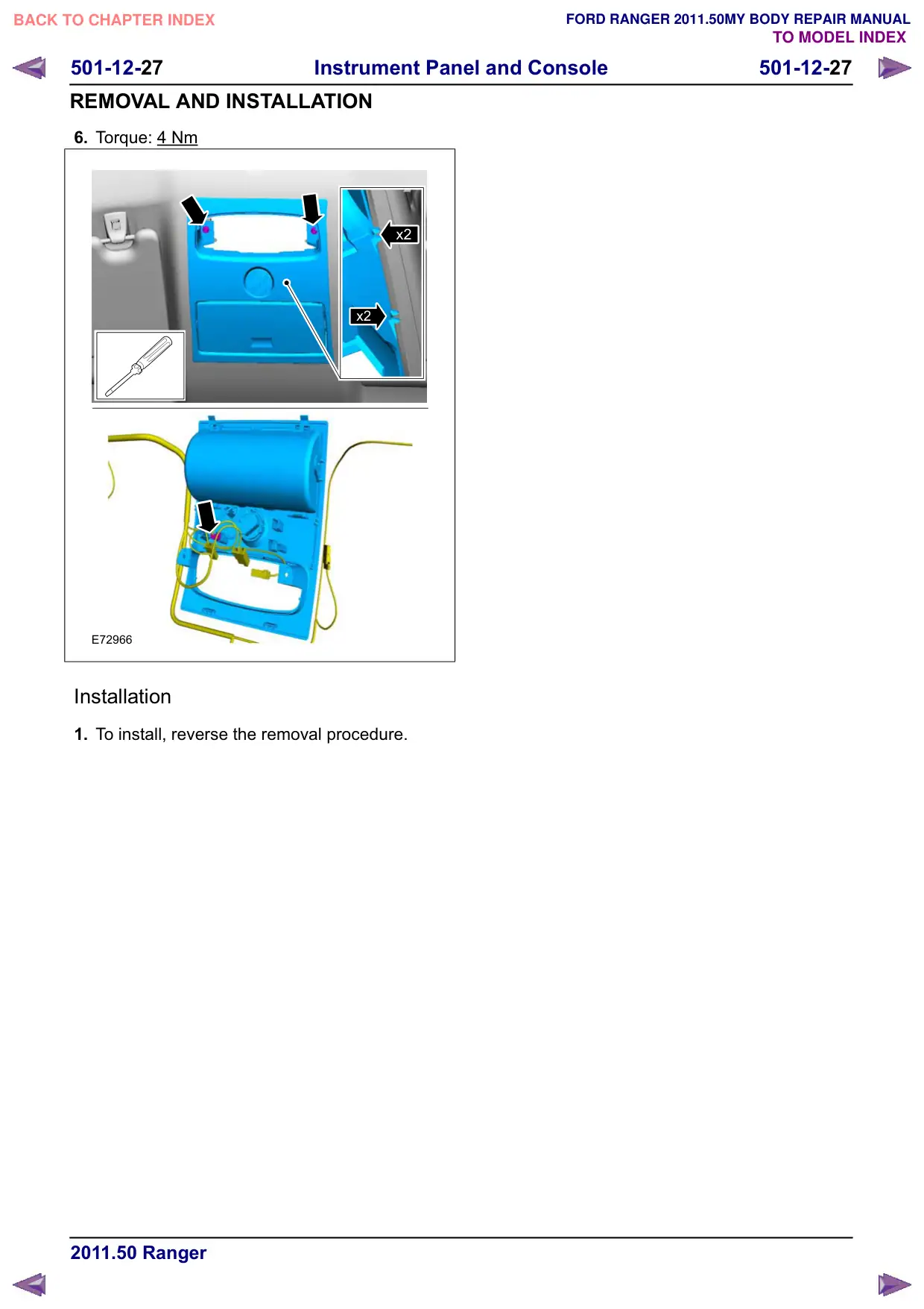
501-12-27 Instrument Panel and Console 501-12-27 REMOVAL AND INSTALLATION 6. Torque: 4 Nm x2 x2 E72966 Installation 1. To install, reverse the removal procedure.

Página 152 · Painel

Instrument Panel

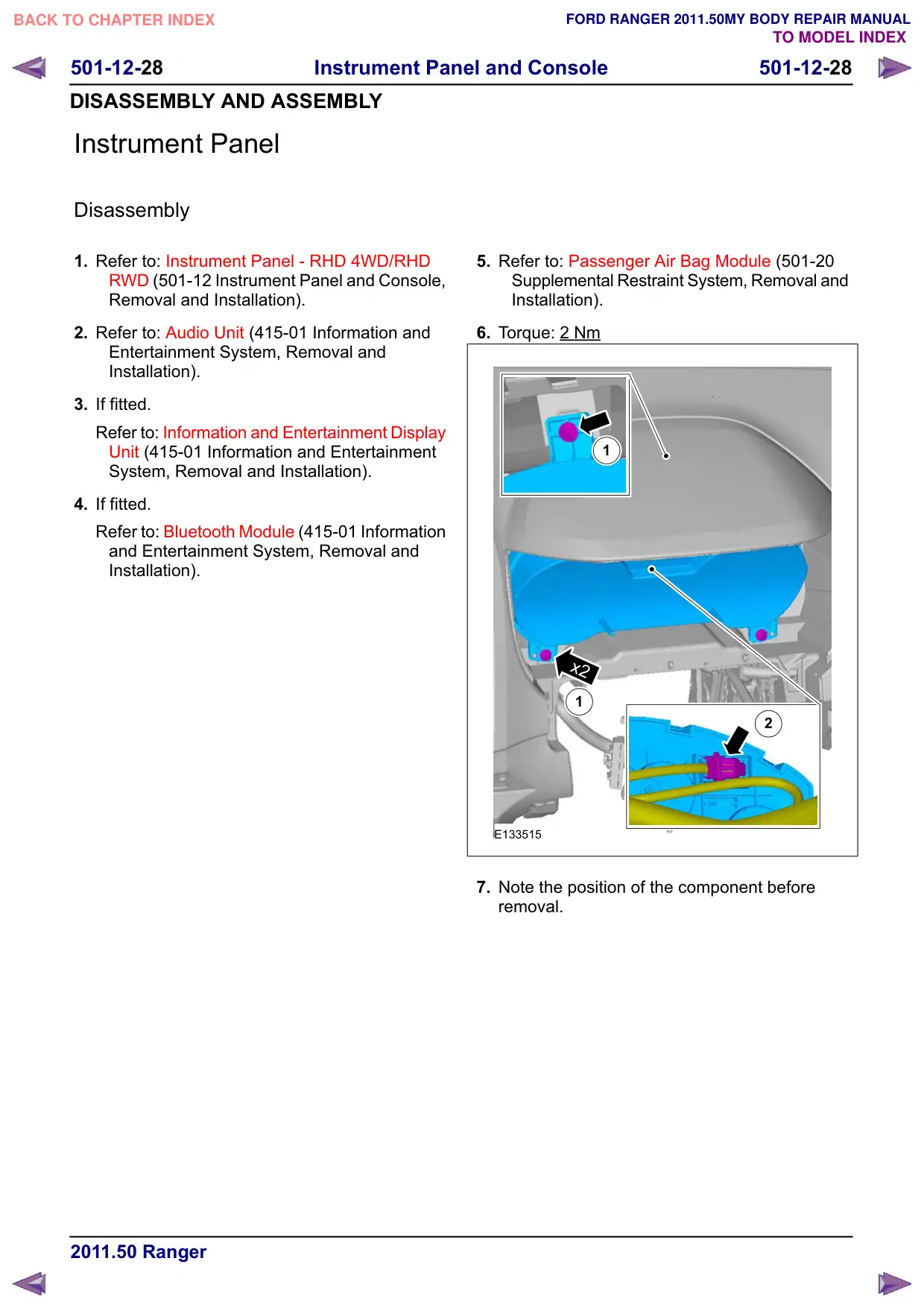
501-12-28 Instrument Panel and Console 501-12-28 DISASSEMBLY AND ASSEMBLY Instrument Panel Disassembly 1. Refer to: Instrument Panel - RHD 4WD/RHD 5:' (501-12 Instrument Panel and Console, Removal and Installation). 2. Refer to: Audio Unit (415-01 Information and Entertainment System, Removal and Installation). 3. If fitted. Refer to: Information and Entertainment Display Unit (415-01 Information and Entertainment System, Removal and Installation). 4. If fitted. Refer to: Bluetooth Module (415-01 Information and Entertainment System, Removal and Installation). 5. Refer to: Passenger Air Bag Module (501-20 Supplemental Restraint System, Removal and Installation). 6. Torque: 2 Nm 1 x2 1 2 E133515 7. Note the position of the component before removal.

Página 153 · Painel

Instrument Panel

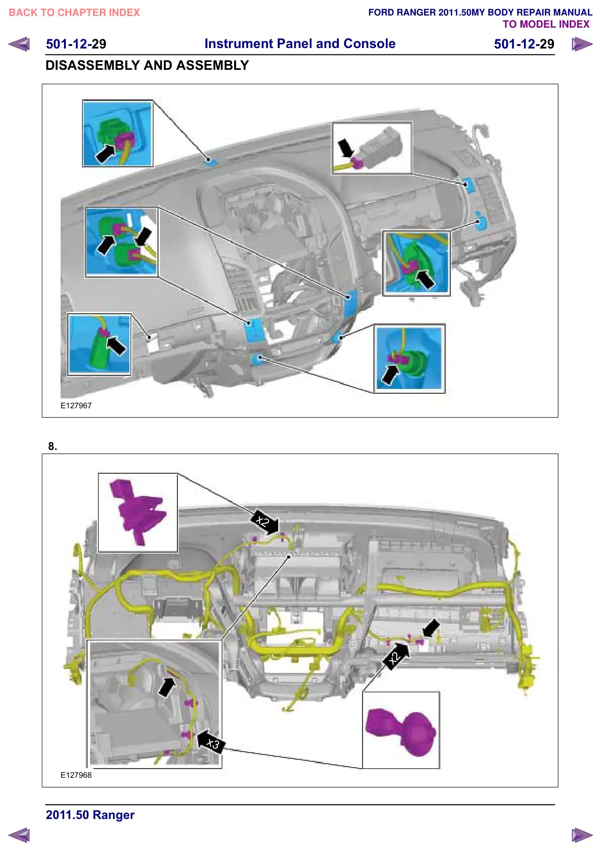
501-12-29 Instrument Panel and Console 501-12-29 DISASSEMBLY AND ASSEMBLY E127967 8. x2 x3 E127968 x2

Página 154 · Painel

Instrument Panel

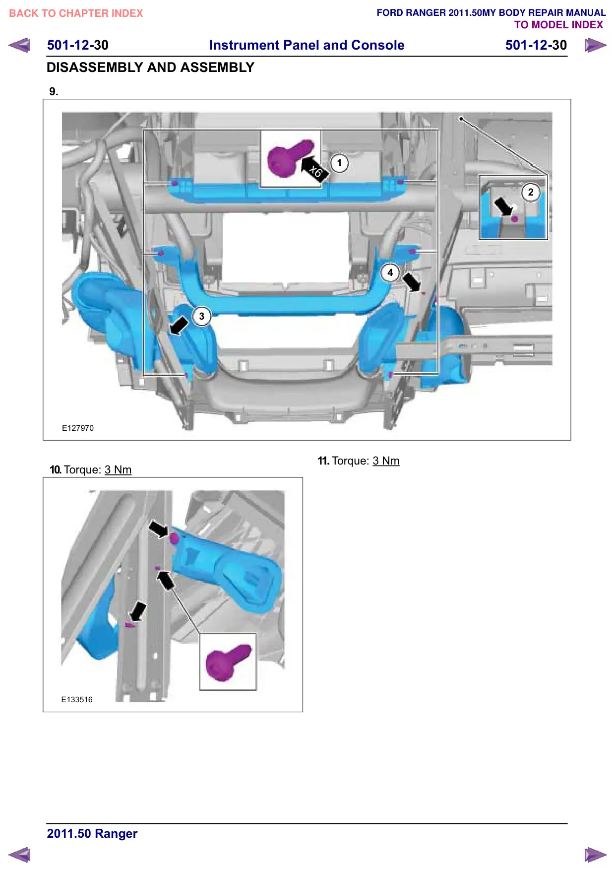
501-12-30 Instrument Panel and Console 501-12-30 DISASSEMBLY AND ASSEMBLY 9. 3 E127970 10.Torque: 3 Nm E133516 1 x6 2 4 11. Torque: 3 Nm

Página 155 · Painel

Instrument Panel

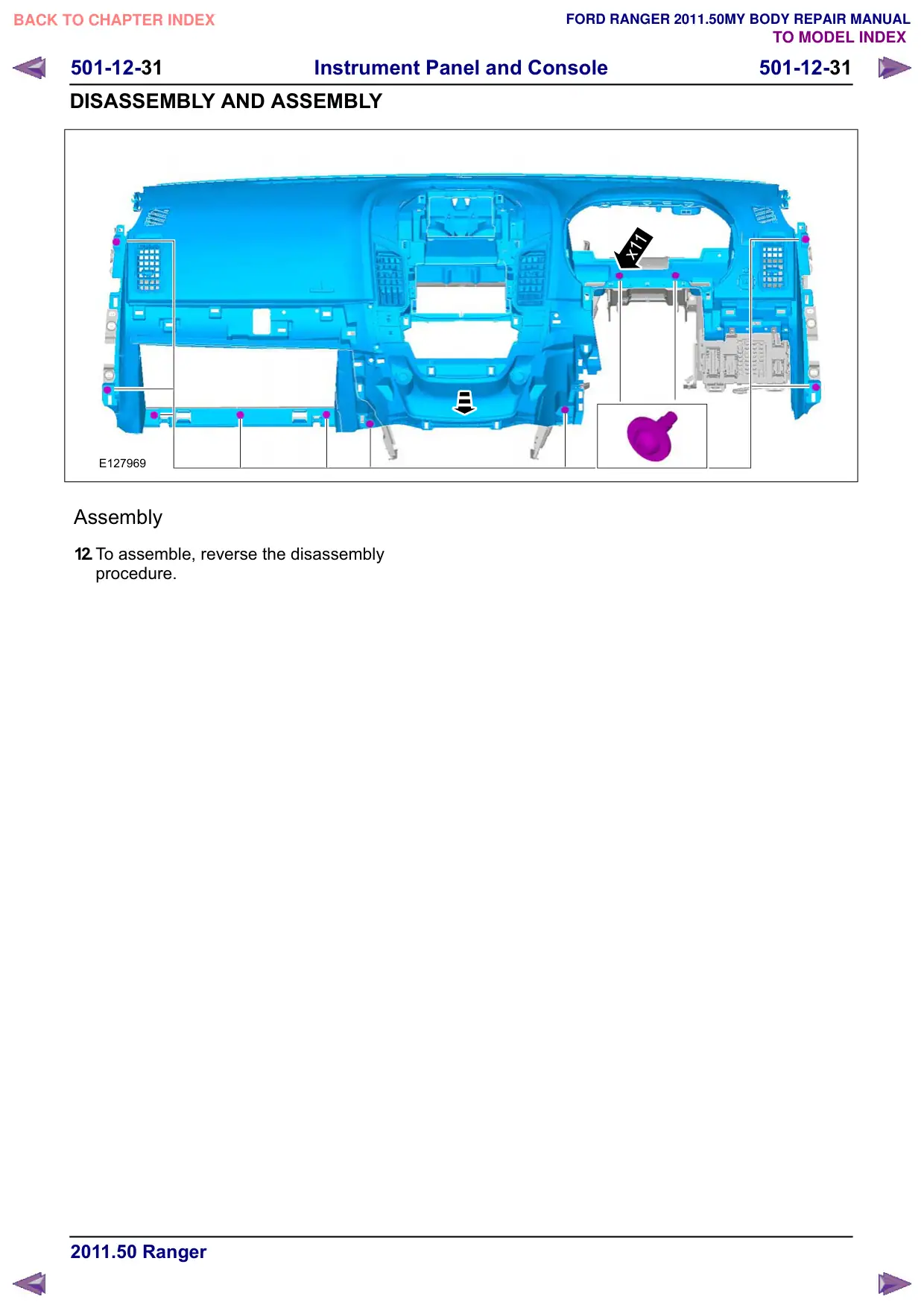
501-12-31 Instrument Panel and Console 501-12-31 DISASSEMBLY AND ASSEMBLY E127969 Assembly 12.To assemble, reverse the disassembly procedure. x11