413-01-4
Instrument Cluster
413-01-4
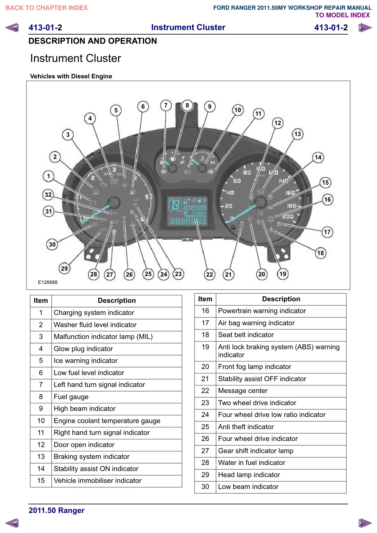
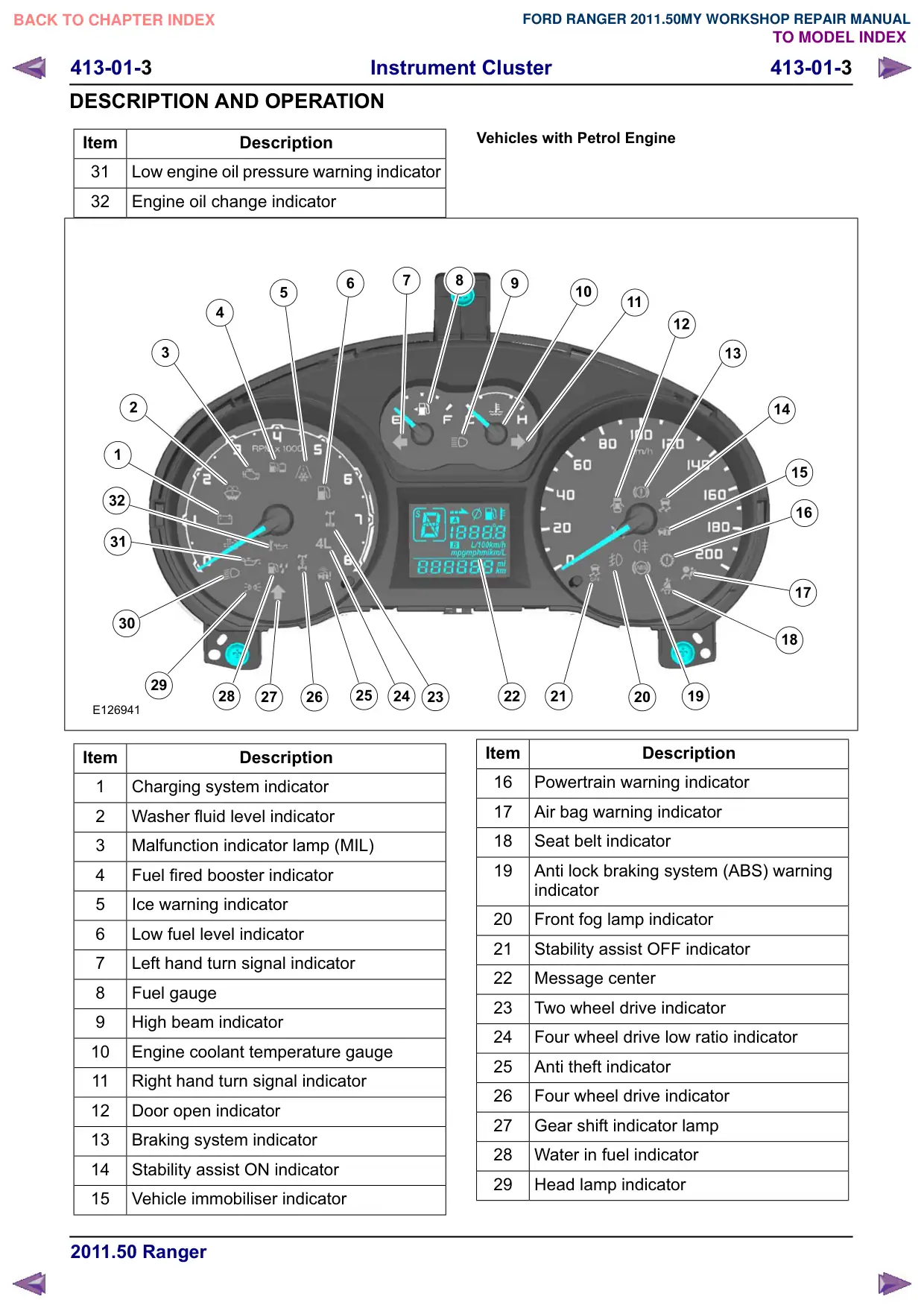
DESCRIPTION AND OPERATION
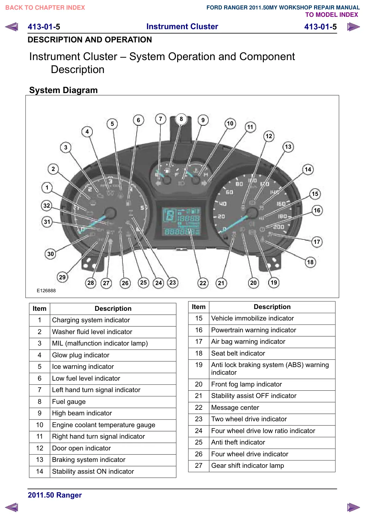
Item
Description
30
Low beam indicator
31
Low engine oil pressure warning indicator
32
Engine oil change indicator
Service instructions
If the instrument cluster is replaced, the data of the
central module configuration must be copied using
IDS (Integrated Diagnostic System) from BCM to
the new instrument cluster. In addition, all vehicle
keys must be relearned. At least two vehicle keys
are needed for relearning.
413-01-6
Instrument Cluster
413-01-6
DESCRIPTION AND OPERATION
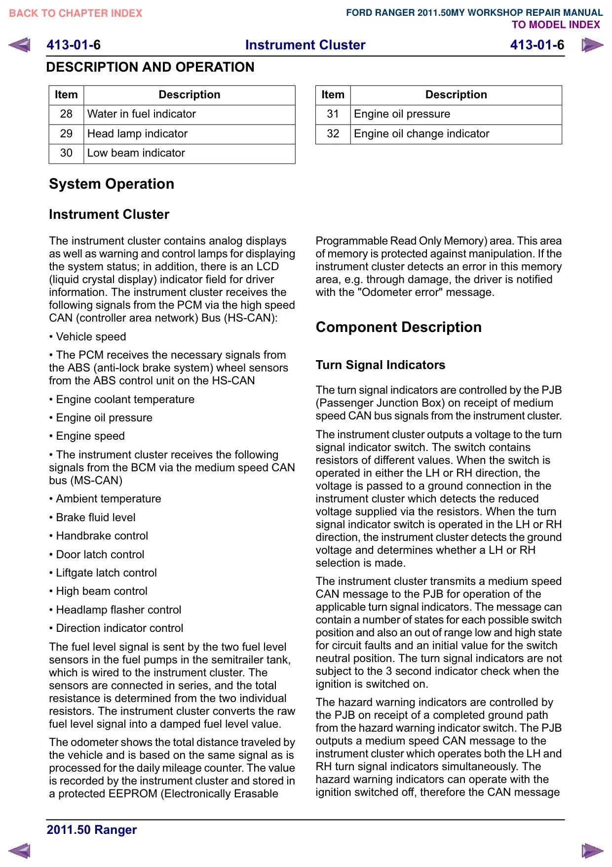
Item
Description
28
Water in fuel indicator
29
Head lamp indicator
30
Low beam indicator
System Operation
Instrument Cluster
The instrument cluster contains analog displays
as well as warning and control lamps for displaying
the system status; in addition, there is an LCD
(liquid crystal display) indicator field for driver
information. The instrument cluster receives the
following signals from the PCM via the high speed
CAN (controller area network) Bus (HS-CAN):
• Vehicle speed
• The PCM receives the necessary signals from
the ABS (anti-lock brake system) wheel sensors
from the ABS control unit on the HS-CAN
• Engine coolant temperature
• Engine oil pressure
• Engine speed
• The instrument cluster receives the following
signals from the BCM via the medium speed CAN
bus (MS-CAN)
• Ambient temperature
• Brake fluid level
• Handbrake control
• Door latch control
• Liftgate latch control
• High beam control
• Headlamp flasher control
• Direction indicator control
The fuel level signal is sent by the two fuel level
sensors in the fuel pumps in the semitrailer tank,
which is wired to the instrument cluster. The
sensors are connected in series, and the total
resistance is determined from the two individual
resistors. The instrument cluster converts the raw
fuel level signal into a damped fuel level value.
The odometer shows the total distance traveled by
the vehicle and is based on the same signal as is
processed for the daily mileage counter. The value
is recorded by the instrument cluster and stored in
a protected EEPROM (Electronically Erasable
Item
Description
31
Engine oil pressure
32
Engine oil change indicator
Programmable Read Only Memory) area. This area
of memory is protected against manipulation. If the
instrument cluster detects an error in this memory
area, e.g. through damage, the driver is notified
with the "Odometer error" message.
Component Description
Turn Signal Indicators
The turn signal indicators are controlled by the PJB
(Passenger Junction Box) on receipt of medium
speed CAN bus signals from the instrument cluster.
The instrument cluster outputs a voltage to the turn
signal indicator switch. The switch contains
resistors of different values. When the switch is
operated in either the LH or RH direction, the
voltage is passed to a ground connection in the
instrument cluster which detects the reduced
voltage supplied via the resistors. When the turn
signal indicator switch is operated in the LH or RH
direction, the instrument cluster detects the ground
voltage and determines whether a LH or RH
selection is made.
The instrument cluster transmits a medium speed
CAN message to the PJB for operation of the
applicable turn signal indicators. The message can
contain a number of states for each possible switch
position and also an out of range low and high state
for circuit faults and an initial value for the switch
neutral position. The turn signal indicators are not
subject to the 3 second indicator check when the
ignition is switched on.
The hazard warning indicators are controlled by
the PJB on receipt of a completed ground path
from the hazard warning indicator switch. The PJB
outputs a medium speed CAN message to the
instrument cluster which operates both the LH and
RH turn signal indicators simultaneously. The
hazard warning indicators can operate with the
ignition switched off, therefore the CAN message
413-01-7
Instrument Cluster
413-01-7
DESCRIPTION AND OPERATION
from the PJB will also carry a 'wake-up' message
for the instrument cluster.
Brake Warning Indicator
The indicator is controlled by high speed CAN
messages from the ABS module and the parking
brake control module. If it illuminates when you are
driving, check that the parking brake is not
engaged. If the parking brake is not engaged, this
indicates a malfunction. Have the system checked
by a properly trained technician immediately.
If a condition exists where the parking brake cannot
be applied, the parking brake control module issues
a CAN message to the instrument cluster which
flashes the warning lamp on and off and is
accompanied with a message 'CANNOT APPLY
PARK BRAKE'. If a fault occurs in the parking
brake system, the parking brake control module
issues a CAN message to the instrument cluster
which illuminates the warning indicator and displays
the message 'PARK BRAKE FAULT' in the
message center.
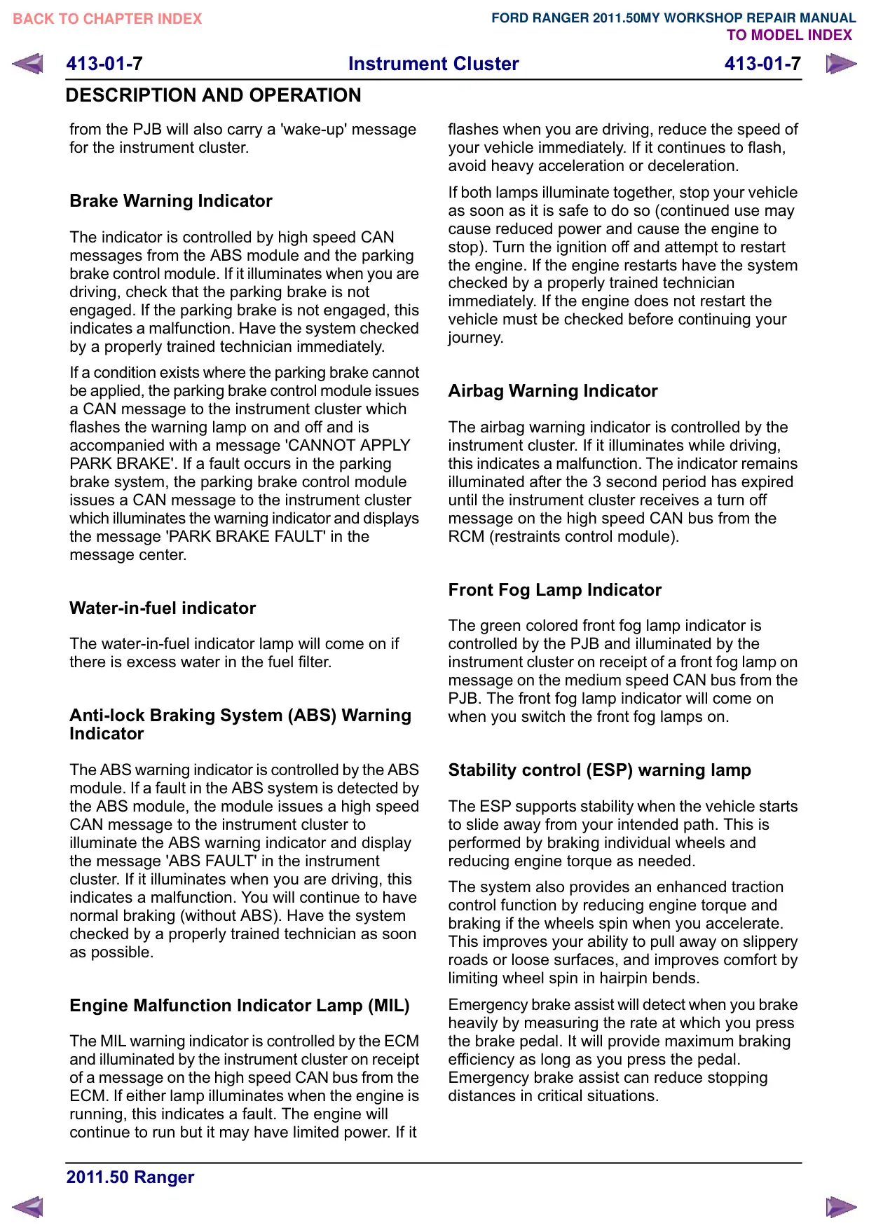
Water-in-fuel indicator
The water-in-fuel indicator lamp will come on if
there is excess water in the fuel filter.
Anti-lock Braking System (ABS) Warning
Indicator
The ABS warning indicator is controlled by the ABS
module. If a fault in the ABS system is detected by
the ABS module, the module issues a high speed
CAN message to the instrument cluster to
illuminate the ABS warning indicator and display
the message 'ABS FAULT' in the instrument
cluster. If it illuminates when you are driving, this
indicates a malfunction. You will continue to have
normal braking (without ABS). Have the system
checked by a properly trained technician as soon
as possible.
Engine Malfunction Indicator Lamp (MIL)
The MIL warning indicator is controlled by the ECM
and illuminated by the instrument cluster on receipt
of a message on the high speed CAN bus from the
ECM. If either lamp illuminates when the engine is
running, this indicates a fault. The engine will
continue to run but it may have limited power. If it
flashes when you are driving, reduce the speed of
your vehicle immediately. If it continues to flash,
avoid heavy acceleration or deceleration.
If both lamps illuminate together, stop your vehicle
as soon as it is safe to do so (continued use may
cause reduced power and cause the engine to
stop). Turn the ignition off and attempt to restart
the engine. If the engine restarts have the system
checked by a properly trained technician
immediately. If the engine does not restart the
vehicle must be checked before continuing your
journey.
Airbag Warning Indicator
The airbag warning indicator is controlled by the
instrument cluster. If it illuminates while driving,
this indicates a malfunction. The indicator remains
illuminated after the 3 second period has expired
until the instrument cluster receives a turn off
message on the high speed CAN bus from the
RCM (restraints control module).
Front Fog Lamp Indicator
The green colored front fog lamp indicator is
controlled by the PJB and illuminated by the
instrument cluster on receipt of a front fog lamp on
message on the medium speed CAN bus from the
PJB. The front fog lamp indicator will come on
when you switch the front fog lamps on.
Stability control (ESP) warning lamp
The ESP supports stability when the vehicle starts
to slide away from your intended path. This is
performed by braking individual wheels and
reducing engine torque as needed.
The system also provides an enhanced traction
control function by reducing engine torque and
braking if the wheels spin when you accelerate.
This improves your ability to pull away on slippery
roads or loose surfaces, and improves comfort by
limiting wheel spin in hairpin bends.
Emergency brake assist will detect when you brake
heavily by measuring the rate at which you press
the brake pedal. It will provide maximum braking
efficiency as long as you press the pedal.
Emergency brake assist can reduce stopping
distances in critical situations.
413-01-8
Instrument Cluster
413-01-8
DESCRIPTION AND OPERATION
Safety Belt Warning Indicator
The safety belt warning indicator operates for both
the driver and passenger safety belts. The warning
indicator is controlled by the RCM and illuminated
by the instrument cluster on receipt of high speed
CAN bus messages. The safety belt warning
indicator is not subject to the 6 second indicator
check when the ignition is switched on.
The safety belt warning indicator is subject to a
timer. The warning indicator is activated when the
following conditions exist:
• The seat belt warning lamp will be illuminated for
6 seconds when the ignition is turned on to remind
the driver to fasten the seatbelt.
• The seat belt warning lamp will be illuminated for
6 seconds when the ignition is turned on and if the
drivers seat belt is not buckled.
• The seat belt reminder warning lamp illuminates
and an audible warning will sound if the driver or
front passenger seat belt has not been fastened
and the vehicle exceeds a relatively low speed. It
will also illuminate if either of the seat belt is
unfastened when the vehicle is moving. The
audible warning will go off after five minutes but
the seat belt reminder warning lamp will remain on
until the seat belt is fastened.
Side Lamp Indicator
The instrument cluster controls the orange colored
side lamp indicator on receipt of a side lamp status
message on the medium speed CAN bus from the
PJB and the auxiliary junction box. Selections using
this switch are detected by the cluster which
requests the side or headlamp operation via a
message to the PJB and the PJB. The PJB and
the RJB responds with a side lamp active message
and the cluster illuminates the side lamp indicator.
The side lamp indicator is not subject to the 3
second indicator check when the ignition is
switched on.
High Beam Indicator
The instrument cluster controls the blue colored
high beam indicator on receipt of a high beam
status message on the medium speed CAN bus
from the PJB. High beam or flash selections using
this switch are detected by the cluster which
requests the light operation via a CAN message
to the PJB. The PJB responds with a high beam
active message and the cluster illuminates the high
beam indicator. The high beam indicator is not
subject to the 3 second indicator check when the
ignition is switched on.
Rear Fog Lamp Indicator
The amber colored rear fog lamp indicator is
controlled by the auxiliary junction box and
illuminated by the instrument cluster on receipt of
a rear fog lamp on . The rear fog lamp indicator
lamp will come on when you switch the rear fog
lamps on. The rear fog lamp indicator is not subject
to the 3 second indicator check when the ignition
is switched on. You cannot switch the rear fog
lamps on unless you have switched the headlamps
and front fog lamp on.
Speedo meter
The speedometer is driven by high speed CAN
signals transmitted by the ABS module. The wheel
speeds are measured by sensors reading the
rotational speed of the rear wheels from toothed
targets on the hubs. An average of the two wheel
speeds are passed from the sensors to the ABS
module in the form of pulsed signals. The ABS
module converts these signals into a speed output
on the high speed CAN to the instrument cluster.
The same speed outputs from the wheel speed
sensors are also used to calculate the distance the
vehicle has traveled.
Tacho meter
The tachometer is driven by an engine speed signal
transmitted on the high speed CAN from the ECM.
The signal is derived from the CKP (crankshaft
position) sensor. The signal is received by the
instrument cluster microprocessor and the output
from the microprocessor drives the tachometer.
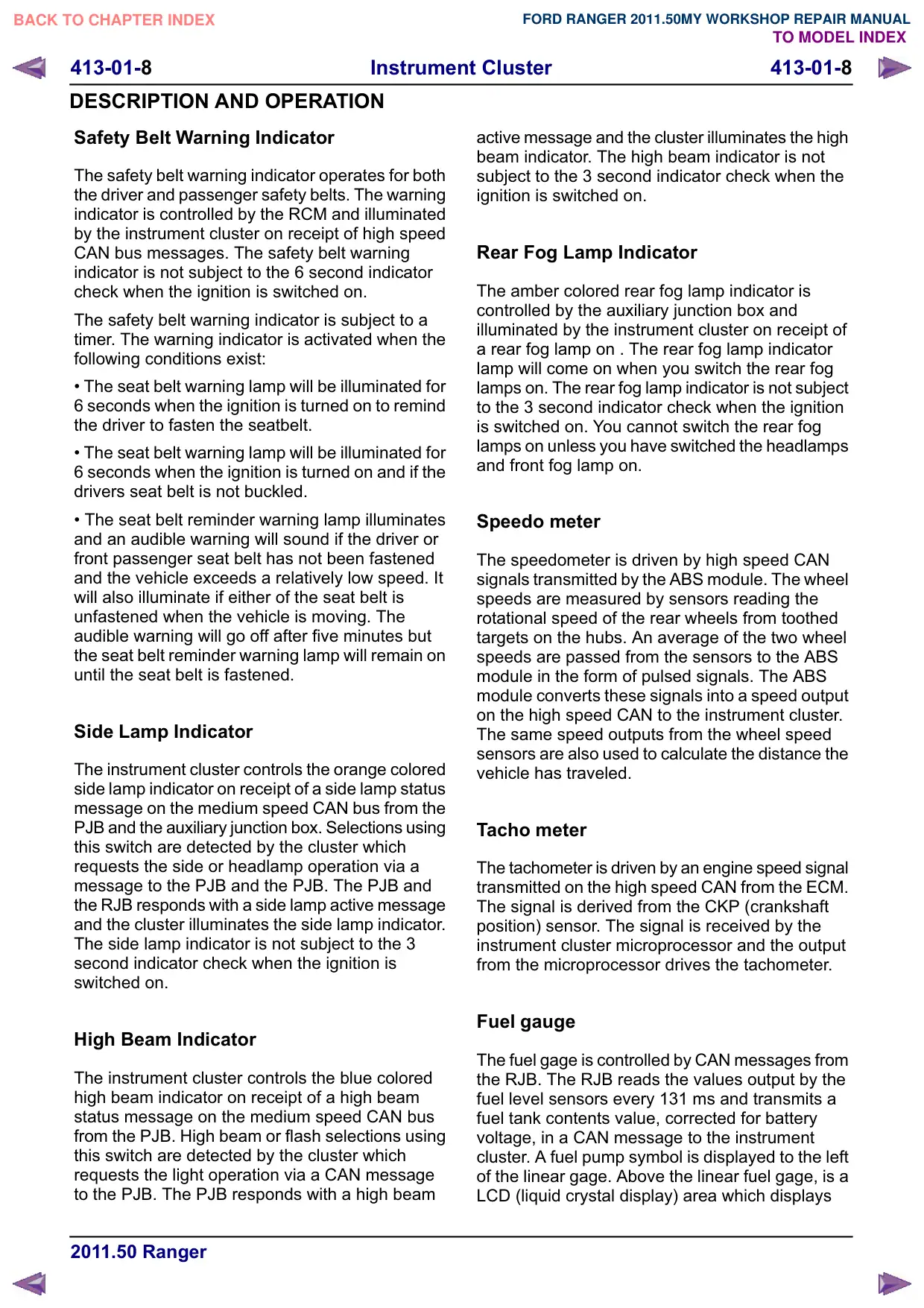
Fuel gauge
The fuel gage is controlled by CAN messages from
the RJB. The RJB reads the values output by the
fuel level sensors every 131 ms and transmits a
fuel tank contents value, corrected for battery
voltage, in a CAN message to the instrument
cluster. A fuel pump symbol is displayed to the left
of the linear gage. Above the linear fuel gage, is a
LCD (liquid crystal display) area which displays
413-01-
Instrument Cluster
413-01-
DESCRIPTION AND OPERATION
odometer and trip readouts. When a trip computer
function is selected, these are replaced by a trip
computer display for the trip function selected.
Liquid crystal display
In liquid crystal display which is located in
instrument cluster displays a linear fuel gage,
odometer, trip distance and trip computer readouts.
The trip distance and trip computer information is
derived from information supplied on the high
speed CAN bus to the instrument cluster from the
ABS module and the ECM.
The area above the message center displays the
transmission gear position information and speed
control related information. The transmission
information is supplied on the high speed CAN bus
from the TCM (transmission control module).
Gear shift indicator lamp
The gear selector module transmits a CAN
message to the instrument cluster for gear selector
lever position. The module also outputs a 'not in
park' signal to the instrument cluster. It will
illuminate to inform you that shifting to a higher
gear may give better fuel economy and lower CO2
emissions.
413-01-10
Instrument Cluster
413-01-10
REMOVAL AND INSTALLATION
Instrument Cluster
General Equipment
Ford Diagnostic Equipment
Removal
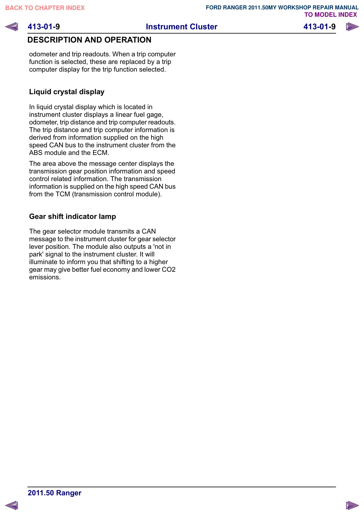
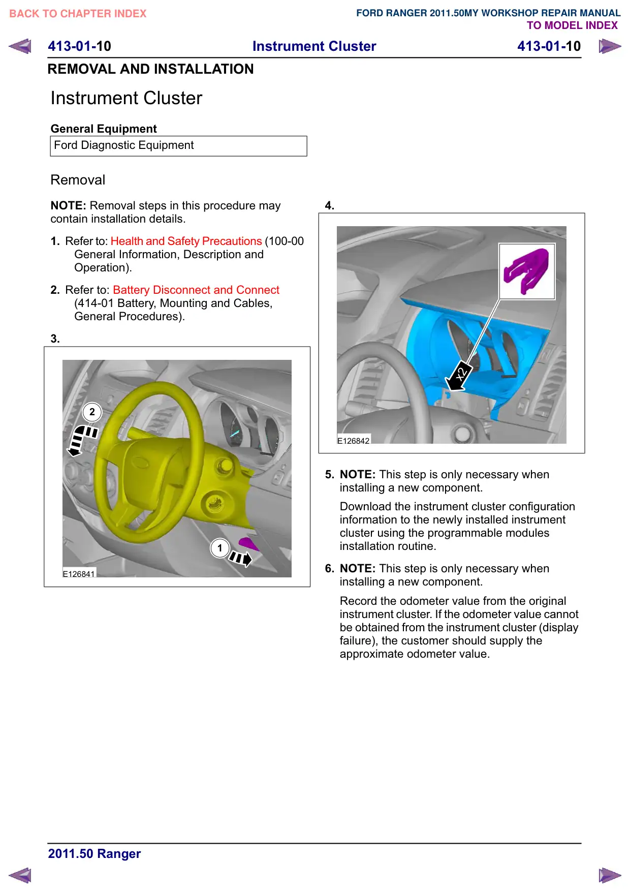
NOTE: Removal steps in this procedure may
contain installation details.
1. Refer to: Health and Safety Precautions (100-00
General Information, Description and
Operation).
2. Refer to: Battery Disconnect and Connect
(414-01 Battery, Mounting and Cables,
General Procedures).
3.
2
1
E126841
4.
x2
E126842
5. NOTE: This step is only necessary when
installing a new component.
Download the instrument cluster configuration
information to the newly installed instrument
cluster using the programmable modules
installation routine.
6. NOTE: This step is only necessary when
installing a new component.
Record the odometer value from the original
instrument cluster. If the odometer value cannot
be obtained from the instrument cluster (display
failure), the customer should supply the
approximate odometer value.
413-01-11
Instrument Cluster
413-01-11
REMOVAL AND INSTALLATION
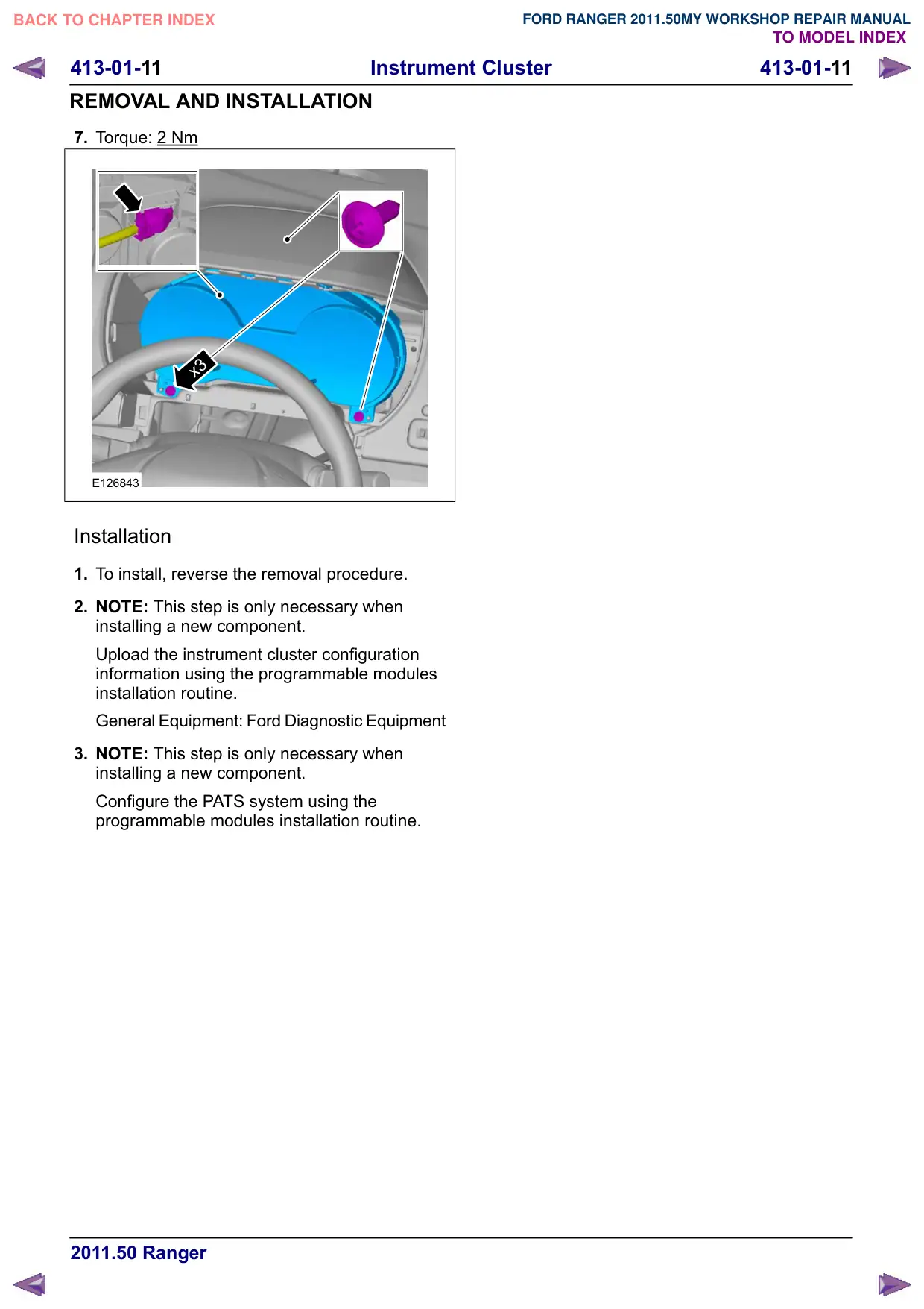
7. Torque: 2 Nm
x3
E126843
Installation
1. To install, reverse the removal procedure.
2. NOTE: This step is only necessary when
installing a new component.
Upload the instrument cluster configuration
information using the programmable modules
installation routine.
General Equipment: Ford Diagnostic Equipment
3. NOTE: This step is only necessary when
installing a new component.
Configure the PATS system using the
programmable modules installation routine.