Painel de instrumentos – Funcionamento do sistema e componentes
Instrument Cluster œ System Operation and Component
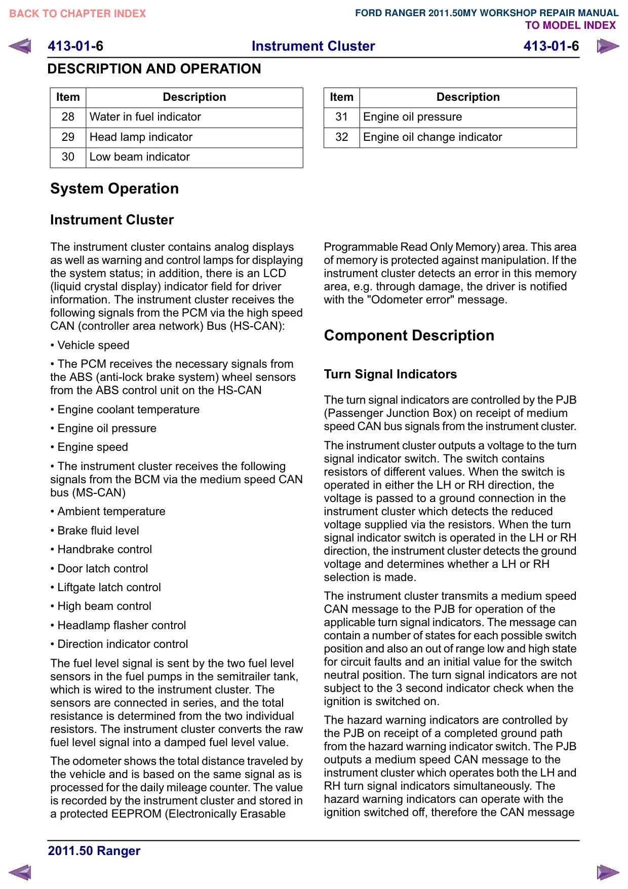
Texto da página
Link desta página: https://ranger.mbrace.com.br/oficina/1210
Imagem: https://ranger.mbrace.com.br/img/oficina/1210.webp
413-01-6
Instrument Cluster
413-01-6
DESCRIPTION AND OPERATION
Item
Description
28
Water in fuel indicator
29
Head lamp indicator
30
Low beam indicator
System Operation
Instrument Cluster
The instrument cluster contains analog displays
as well as warning and control lamps for displaying
the system status; in addition, there is an LCD
(liquid crystal display) indicator field for driver
information. The instrument cluster receives the
following signals from the PCM via the high speed
CAN (controller area network) Bus (HS-CAN):
• Vehicle speed
• The PCM receives the necessary signals from
the ABS (anti-lock brake system) wheel sensors
from the ABS control unit on the HS-CAN
• Engine coolant temperature
• Engine oil pressure
• Engine speed
• The instrument cluster receives the following
signals from the BCM via the medium speed CAN
bus (MS-CAN)
• Ambient temperature
• Brake fluid level
• Handbrake control
• Door latch control
• Liftgate latch control
• High beam control
• Headlamp flasher control
• Direction indicator control
The fuel level signal is sent by the two fuel level
sensors in the fuel pumps in the semitrailer tank,
which is wired to the instrument cluster. The
sensors are connected in series, and the total
resistance is determined from the two individual
resistors. The instrument cluster converts the raw
fuel level signal into a damped fuel level value.
The odometer shows the total distance traveled by
the vehicle and is based on the same signal as is
processed for the daily mileage counter. The value
is recorded by the instrument cluster and stored in
a protected EEPROM (Electronically Erasable
Item
Description
31
Engine oil pressure
32
Engine oil change indicator
Programmable Read Only Memory) area. This area
of memory is protected against manipulation. If the
instrument cluster detects an error in this memory
area, e.g. through damage, the driver is notified
with the "Odometer error" message.
Component Description
Turn Signal Indicators
The turn signal indicators are controlled by the PJB
(Passenger Junction Box) on receipt of medium
speed CAN bus signals from the instrument cluster.
The instrument cluster outputs a voltage to the turn
signal indicator switch. The switch contains
resistors of different values. When the switch is
operated in either the LH or RH direction, the
voltage is passed to a ground connection in the
instrument cluster which detects the reduced
voltage supplied via the resistors. When the turn
signal indicator switch is operated in the LH or RH
direction, the instrument cluster detects the ground
voltage and determines whether a LH or RH
selection is made.
The instrument cluster transmits a medium speed
CAN message to the PJB for operation of the
applicable turn signal indicators. The message can
contain a number of states for each possible switch
position and also an out of range low and high state
for circuit faults and an initial value for the switch
neutral position. The turn signal indicators are not
subject to the 3 second indicator check when the
ignition is switched on.
The hazard warning indicators are controlled by
the PJB on receipt of a completed ground path
from the hazard warning indicator switch. The PJB
outputs a medium speed CAN message to the
instrument cluster which operates both the LH and
RH turn signal indicators simultaneously. The
hazard warning indicators can operate with the
ignition switched off, therefore the CAN message