General Information
100-00-1
100-00-1
.
SECTION 100-00 General Information
VEHICLE APPLICATION: 2011.50 Ranger
CONTENTS
DESCRIPTION AND OPERATION
About This Manual..............................................................................................................
Introduction.........................................................................................................................
How to Use This Manual - Repair Procedures...................................................................
Special Tools......................................................................................................................
Important Safety Instructions..............................................................................................
Warnings, Cautions and Notes in This Manual..................................................................
Overview Procedures.........................................................................................................
Trustmark Authoring Standards (TAS) Procedures............................................................
How to Use This Manual - Diagnosis and Testing procedures ..........................................
Symbols Glossary...............................................................................................................
Health and Safety Precautions...........................................................................................
Introduction.........................................................................................................................
Acids and Alkalis................................................................................................................
Air Bags..............................................................................................................................
Air Conditioning Refrigerant...............................................................................................
Adhesives and Sealers.......................................................................................................
Antifreeze...........................................................................................................................
Asbestos.............................................................................................................................
Battery Acids......................................................................................................................
Brake and Clutch Linings and Pads...................................................................................
Brake Fluids (Polyalkylene Glycols)...................................................................................
Brazing...............................................................................................................................
Chemical Materials.............................................................................................................
Chlorofluorocarbons (CFC)................................................................................................
Clutch Fluids.......................................................................................................................
Clutch Linings and Pads.....................................................................................................
Corrosion Protection Materials...........................................................................................
Cutting................................................................................................................................
Dewaxing............................................................................................................................
Dusts..................................................................................................................................
Electric Shock.....................................................................................................................
Engine Oils.........................................................................................................................
Exhaust Fumes...................................................................................................................
Fibre Insulation...................................................................................................................
Fire.....................................................................................................................................
First Aid..............................................................................................................................
Fluoroelastomer..................................................................................................................
Foams - Polyurethane........................................................................................................
Freon..................................................................................................................................
Fuels...................................................................................................................................
Gas Cylinders.....................................................................................................................
Gases.................................................................................................................................
Gaskets (Fluoroelastomer).................................................................................................
General Workshop Tools and Equipment...........................................................................
PAGE
100-00-3
100-00-3
100-00-3
100-00-3
100-00-3
100-00-3
100-00-3
100-00-5
100-00-15
100-00-16
100-00-38
100-00-38
100-00-38
100-00-38
100-00-38
100-00-39
100-00-40
100-00-40
100-00-40
100-00-40
100-00-40
100-00-40
100-00-40
100-00-41
100-00-41
100-00-41
100-00-41
100-00-41
100-00-41
100-00-42
100-00-42
100-00-42
100-00-42
100-00-42
100-00-42
100-00-43
100-00-43
100-00-43
100-00-43
100-00-43
100-00-44
100-00-44
100-00-44
100-00-44
General Information
100-00-2
100-00-2
.
High Pressure Air, Lubrication and Oil Test Equipment......................................................
Halon..................................................................................................................................
Legal Aspects.....................................................................................................................
Lubricants and Greases.....................................................................................................
Transmission Fluids............................................................................................................
Noise..................................................................................................................................
Noise Insulation Materials..................................................................................................
O-Rings (Fluoroelastomer).................................................................................................
Paints..................................................................................................................................
Pressurized Equipment......................................................................................................
Solder.................................................................................................................................
Solvents..............................................................................................................................
Sound Insulation.................................................................................................................
Suspended Loads...............................................................................................................
Transmission Brake Bands.................................................................................................
Underseal...........................................................................................................................
Viton....................................................................................................................................
Welding...............................................................................................................................
Warning Symbols on Vehicles............................................................................................
White Spirit.........................................................................................................................
Standard Workshop Practices............................................................................................
Vehicle in Workshop...........................................................................................................
Towing the Vehicle..............................................................................................................
Connecting a Slave Battery Using Jumper Cables............................................................
Component Cleaning..........................................................................................................
Calibration of Essential Measuring Equipment...................................................................
Solvents, Sealants and Adhesives.....................................................................................
Introduction.........................................................................................................................
Road/Roller Testing............................................................................................................
Pre-Test Checks.................................................................................................................
Starting the Engine.............................................................................................................
Road or Roller Testing........................................................................................................
Brake Testing......................................................................................................................
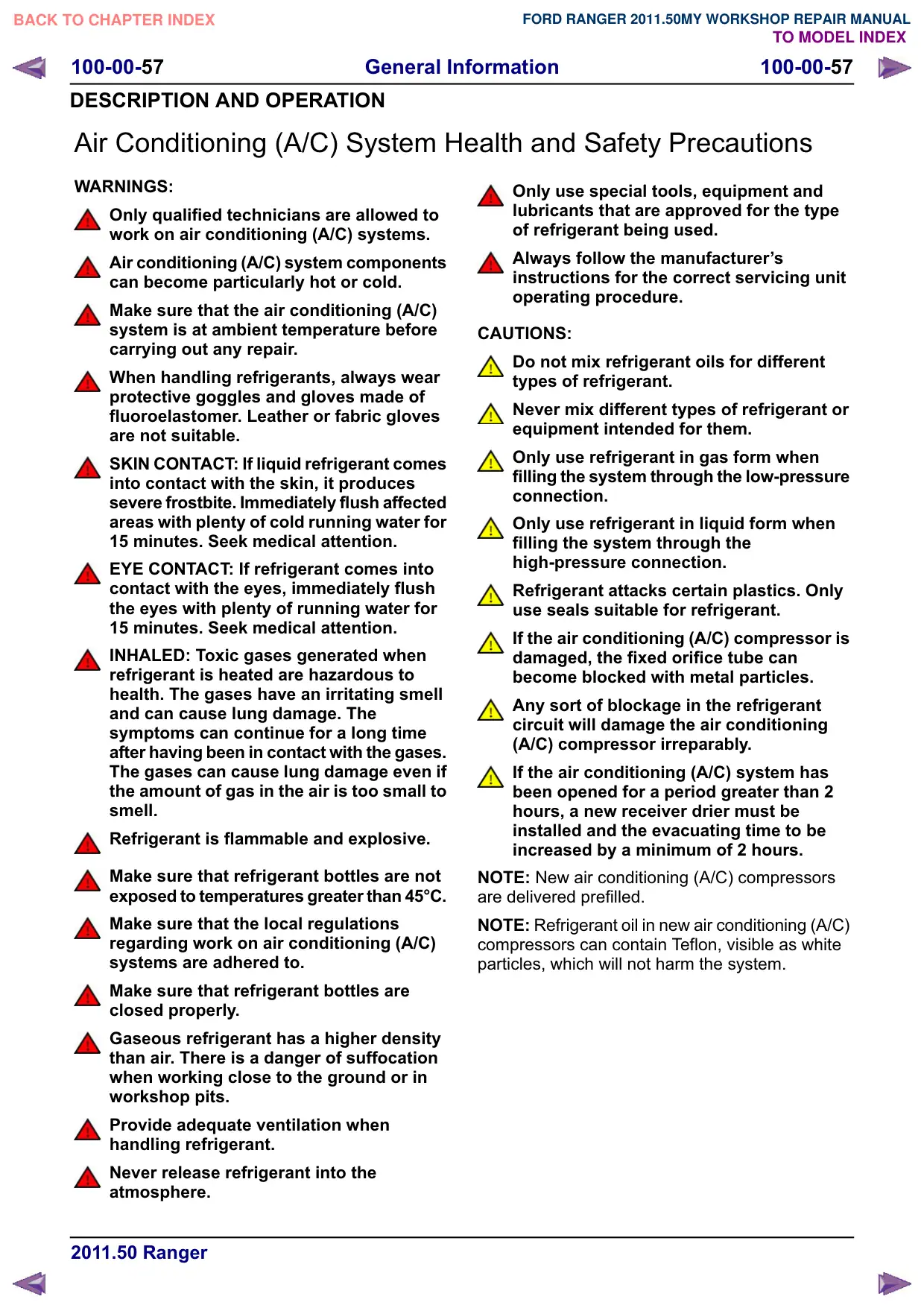
Air Conditioning (A/C) System Health and Safety Precautions..........................................
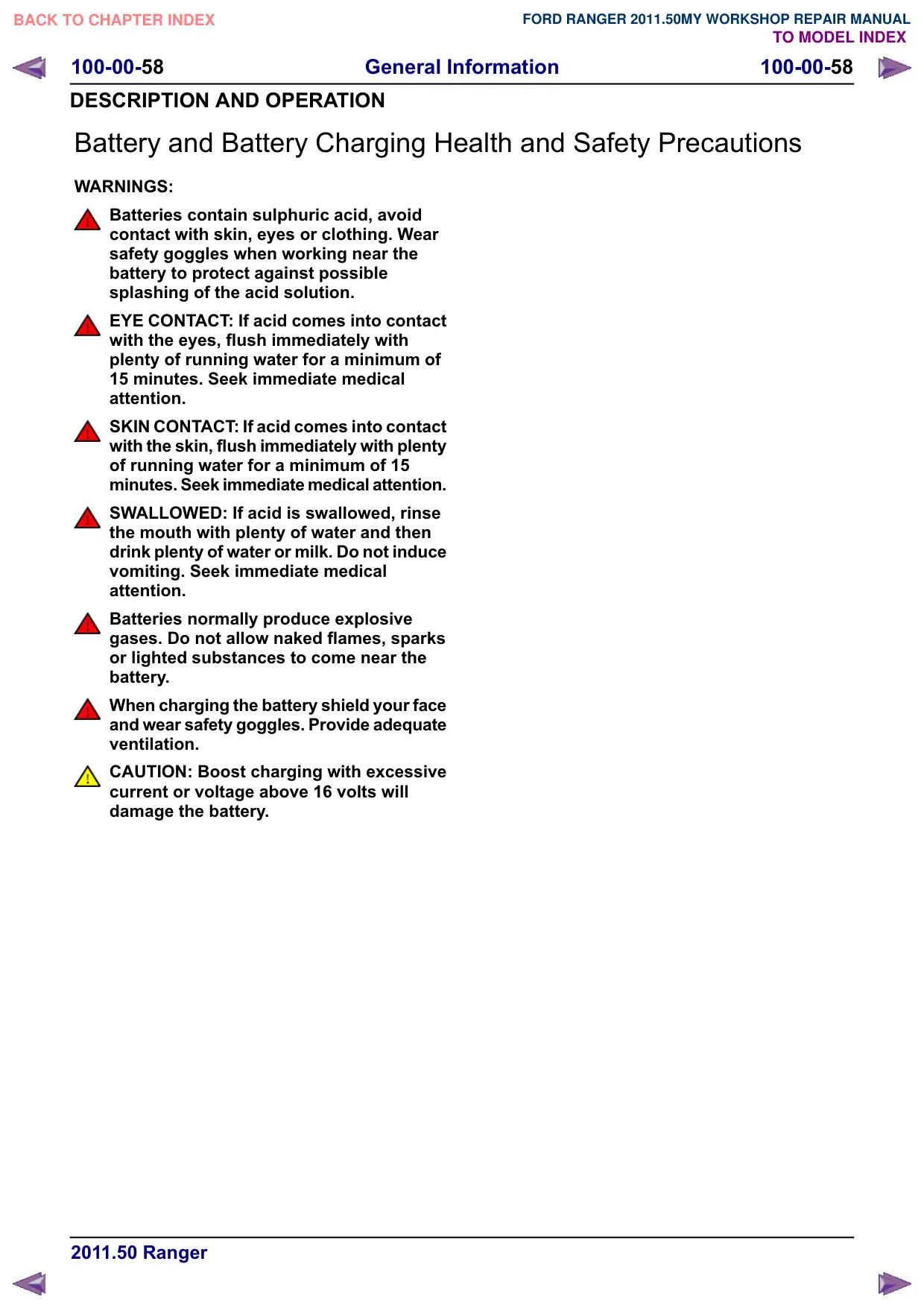
Battery and Battery Charging Health and Safety Precautions............................................
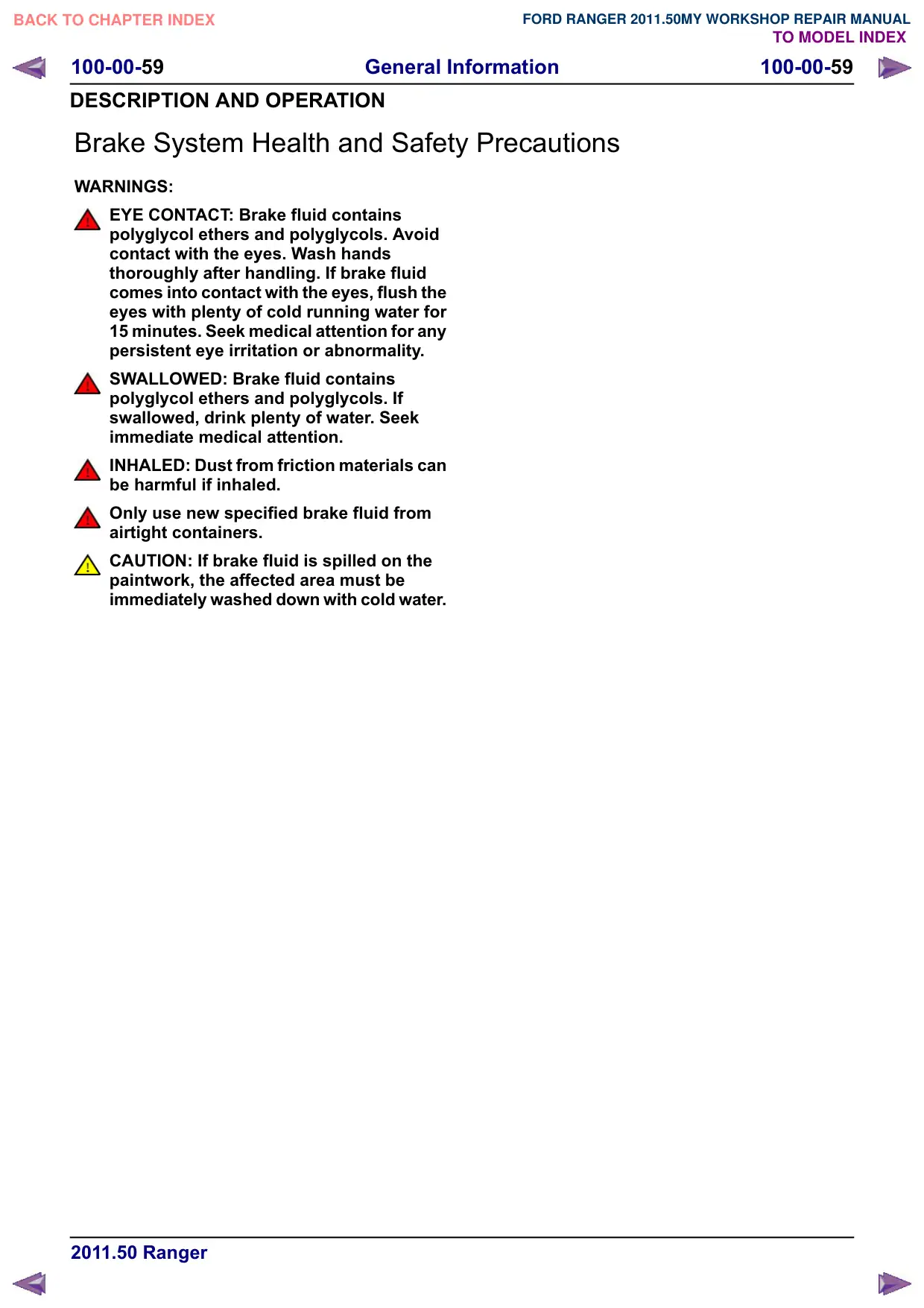
Brake System Health and Safety Precautions....................................................................
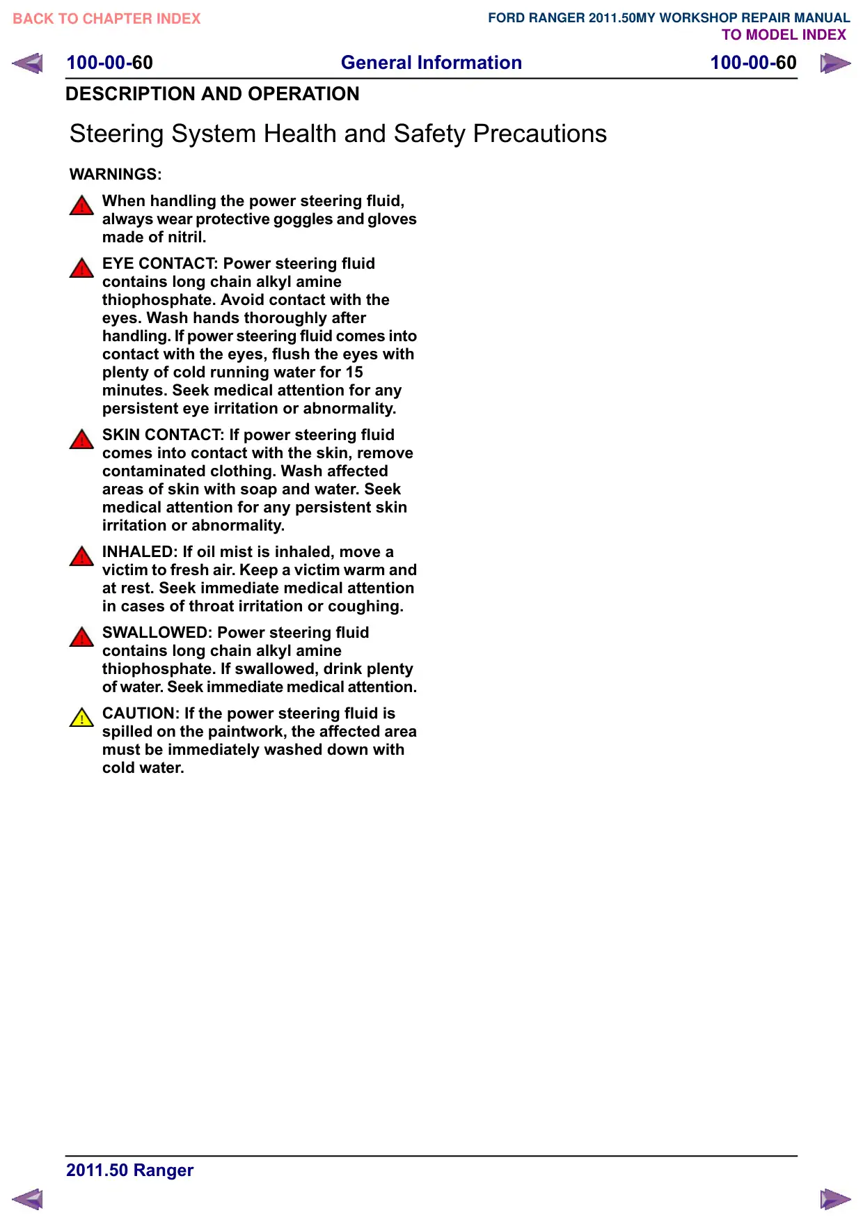
Steering System Health and Safety Precautions................................................................
Engine Cooling System Health and Safety Precautions.....................................................
Petrol and Petrol-Ethanol Fuel Systems Health and Safety Precautions...........................
Diesel Fuel System Health and Safety Precautions...........................................................
Liquefied Petroleum Gas (LPG) Fuel Systems Health and Safety Precautions.................
Compressed Natural Gas (CNG) Fuel Systems Health and Safety Precautions...............
Supplemental Restraint System (SRS) Health and Safety Precautions.............................
Window Glass Health and Safety Precautions...................................................................
100-00-45
100-00-45
100-00-45
100-00-45
100-00-45
100-00-46
100-00-46
100-00-46
100-00-46
100-00-47
100-00-47
100-00-47
100-00-47
100-00-47
100-00-48
100-00-48
100-00-48
100-00-48
100-00-49
100-00-50
100-00-51
100-00-51
100-00-51
100-00-51
100-00-52
100-00-52
100-00-54
100-00-54
100-00-55
100-00-55
100-00-55
100-00-55
100-00-56
100-00-57
100-00-58
100-00-59
100-00-60
100-00-61
100-00-62
100-00-63
100-00-64
100-00-65
100-00-66
100-00-67
General Information
100-00-3
100-00-3
DESCRIPTION AND OPERATION
About This Manual
Introduction
This manual covers diagnosis and testing and
repair procedures.
This manual is structured into groups and sections,
with specific system sections collected together
under their relevant group.
A group covers a specific portion of the vehicle.
The manual is divided into five groups, General
Information, Chassis, Powertrain, Electrical and
Body and Paint. The number of the group is the
first number of a section number.
Within Etis, the navigation tree will list the groups.
After selecting a group the navigation tree will then
list the sections within that group. Each section has
a contents list detailing Specifications, Description
and Operation, Diagnosis and Testing, General
Procedures, Disassembly and Assembly, Removal
and Installation.
If components need to be removed or
disassembled in sequence, the sequence will be
identified numerically in a graphic and the
corresponding text will be numbered accordingly.
All left-hand and right-hand references to the
vehicle are taken from a position sitting in the driver
seat looking forward.
All left-hand and right-hand references to the
engine are taken from a position at the flywheel
looking towards the front camshaft pulley.
How to Use This Manual - Repair
Procedures
This manual has been written in a format that is
designed to meet the needs of technicians
worldwide. The objective is to use common formats
and include similar content in each manual.
This manual provides general descriptions for
accomplishing diagnosis and testing, service and
repair work with tested, effective techniques.
Following them will help assure reliability.
Special Tools
The special tool(s) table provided at the beginning
of each procedure shows all special tools required
to carry out a repair. Where possible, illustrations
are provided to assist in identifying the special tool
required.
Important Safety Instructions
Appropriate service methods and correct repair
procedures are essential for the safe, reliable
operation of all motor vehicles as well as the
personal safety of the individual carrying out the
work.
This manual cannot possibly anticipate all such
variations and provide advice or cautions as to
each. Anyone who departs from the instructions
provided in this manual must first establish that he
compromises neither his personal safety nor the
vehicle integrity by his choice of methods, tools or
components.
Warnings, Cautions and Notes in This
Manual
WARNING: Warnings are used to indicate
that failure to follow a procedure correctly
may result in personal injury.
CAUTION: Cautions are used to indicate
that failure to follow a procedure correctly
may result in damage to the vehicle or
equipment being used.
NOTE: Notes are used to provide additional
essential information required to carry out a
complete and satisfactory repair.
A warning, caution or note is placed at the
beginning of a series of steps if it applies to multiple
steps. If the warning, caution or note only applies
to one step, it is placed at the beginning of the
specific step (after the step number).
Overview Procedures
Overview procedures contain an exploded view
illustration(s). The numbered sequence within the
illustration(s) indicate the order to be followed when
removing/disassembling or when
installing/assembling a component. Additional
information, symbol(s) or a torque figure, may also
be shown alongside the component.
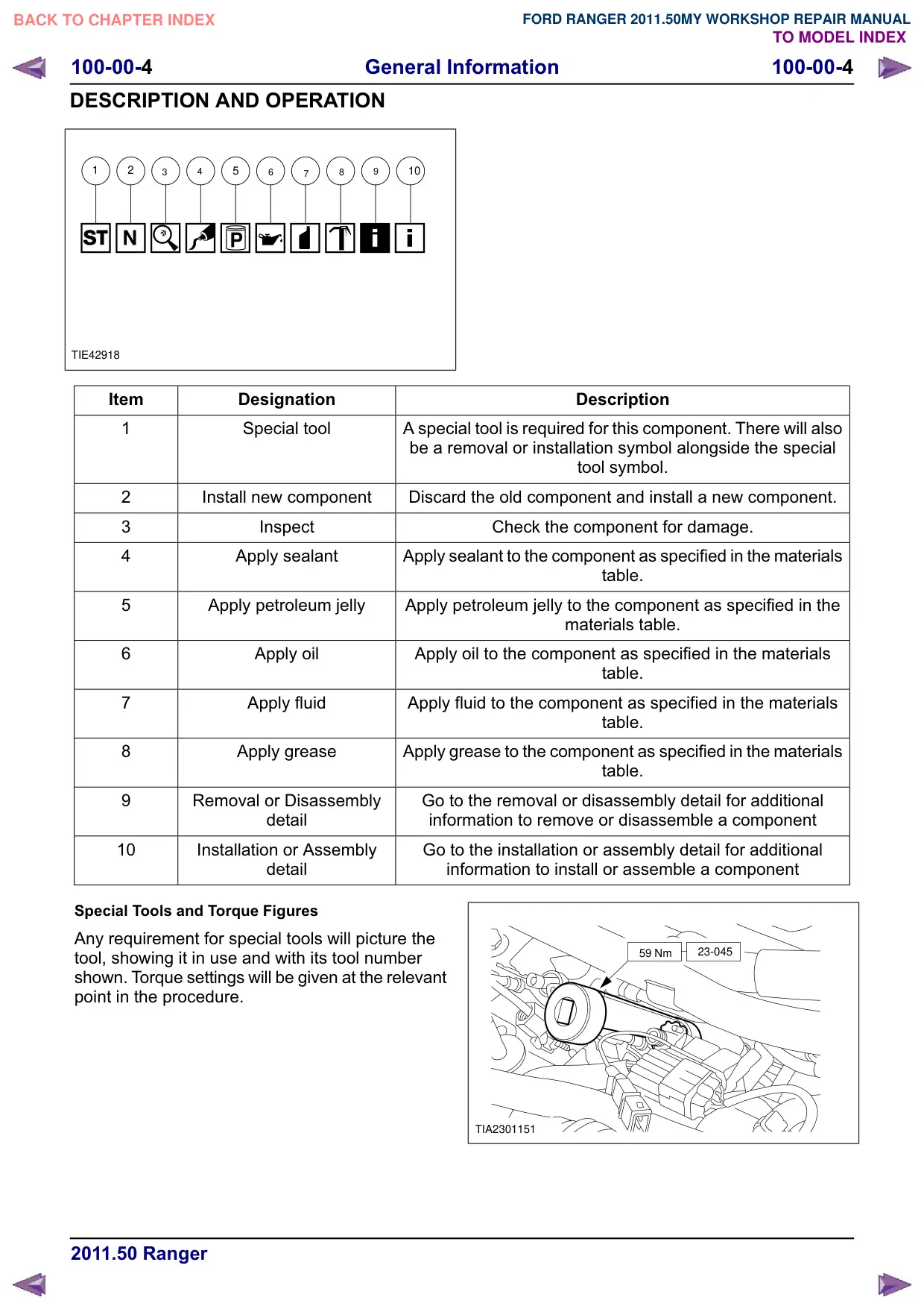
There are ten symbols used to give additional
information when removing/disassembling or when
installing/assembling a component.
General Information
100-00-4
100-00-4
DESCRIPTION AND OPERATION
1
2
3
4
5
6
7
8
9
10
TIE42918
Item
Designation
1
Special tool
A special tool is required for this component. There will also
be a removal or installation symbol alongside the special
2
Install new component
Discard the old component and install a new component.
3
Inspect
4
Apply sealant
Apply sealant to the component as specified in the materials
5
Apply petroleum jelly
Apply petroleum jelly to the component as specified in the
6
Apply oil
Apply oil to the component as specified in the materials
7
Apply fluid
Apply fluid to the component as specified in the materials
8
Apply grease
Apply grease to the component as specified in the materials
Removal or Disassembly
Go to the removal or disassembly detail for additional
detail
information to remove or disassemble a component
10
Installation or Assembly
Go to the installation or assembly detail for additional
detail
Special Tools and Torque Figures
Any requirement for special tools will picture the
tool, showing it in use and with its tool number
shown. Torque settings will be given at the relevant
point in the procedure.
Description
tool symbol.
Check the component for damage.
table.
materials table.
table.
table.
table.
information to install or assemble a component
59 Nm
23-045
TIA2301151
General Information
100-00-5
100-00-5
DESCRIPTION AND OPERATION
Trustmark Authoring Standards (TAS)
Procedures
NOTE: TAS style procedures can be identified by
steps that have no accompanying step text and
the magenta color of the electrical connectors and
fasteners such as nuts, bolts, clamps or clips.
A TAS removal and installation procedure uses a
sequence of color illustrations to indicate the order
to be followed when removing/disassembling or
installing/assembling a component.
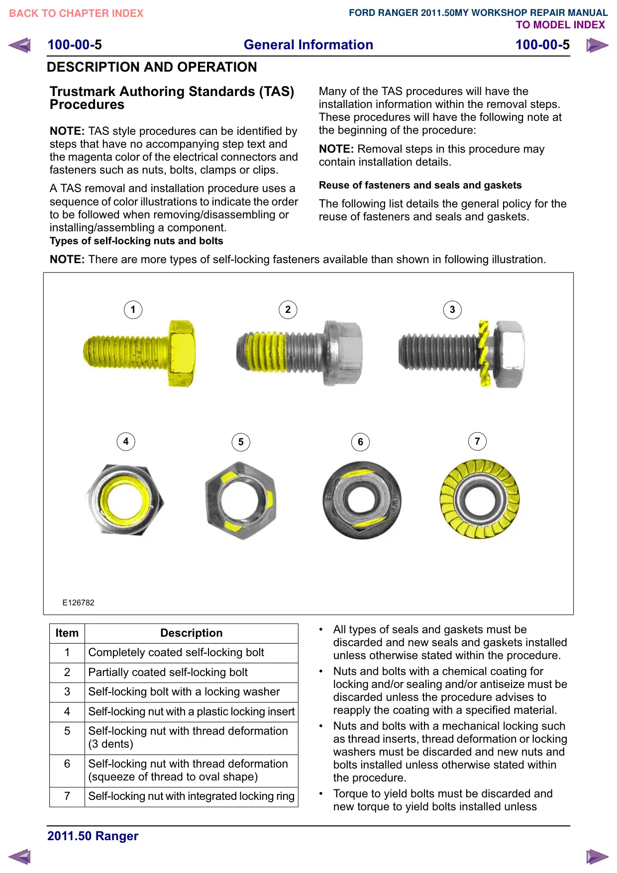
Types of self-locking nuts and bolts
NOTE: There are more types of self-locking fasteners available than shown in following illustration.
1
2
4
5
E126782
Item
Description
1
Completely coated self-locking bolt
2
Partially coated self-locking bolt
3
Self-locking bolt with a locking washer
4
Self-locking nut with a plastic locking insert
5
Self-locking nut with thread deformation
(3 dents)
6
Self-locking nut with thread deformation
(squeeze of thread to oval shape)
7
Self-locking nut with integrated locking ring
Many of the TAS procedures will have the
installation information within the removal steps.
These procedures will have the following note at
the beginning of the procedure:
NOTE: Removal steps in this procedure may
contain installation details.
Reuse of fasteners and seals and gaskets
The following list details the general policy for the
reuse of fasteners and seals and gaskets.
3
6
7
All types of seals and gaskets must be
discarded and new seals and gaskets installed
unless otherwise stated within the procedure.
Nuts and bolts with a chemical coating for
locking and/or sealing and/or antiseize must be
discarded unless the procedure advises to
reapply the coating with a specified material.
Nuts and bolts with a mechanical locking such
as thread inserts, thread deformation or locking
washers must be discarded and new nuts and
bolts installed unless otherwise stated within
the procedure.
Torque to yield bolts must be discarded and
new torque to yield bolts installed unless
General Information
100-00-6
100-00-6
DESCRIPTION AND OPERATION
otherwise stated within the procedure,
recognizable by a tightening torque with more
than one stage together with a torque angle.
Specification procedures will contain all technical
data that are not part of a repair procedure.
Reuse of exterior trim parts
All type of glued exterior trim parts or parts
fastened with adhesive tape must be discarded
and new parts installed unless otherwise stated
within the procedure.
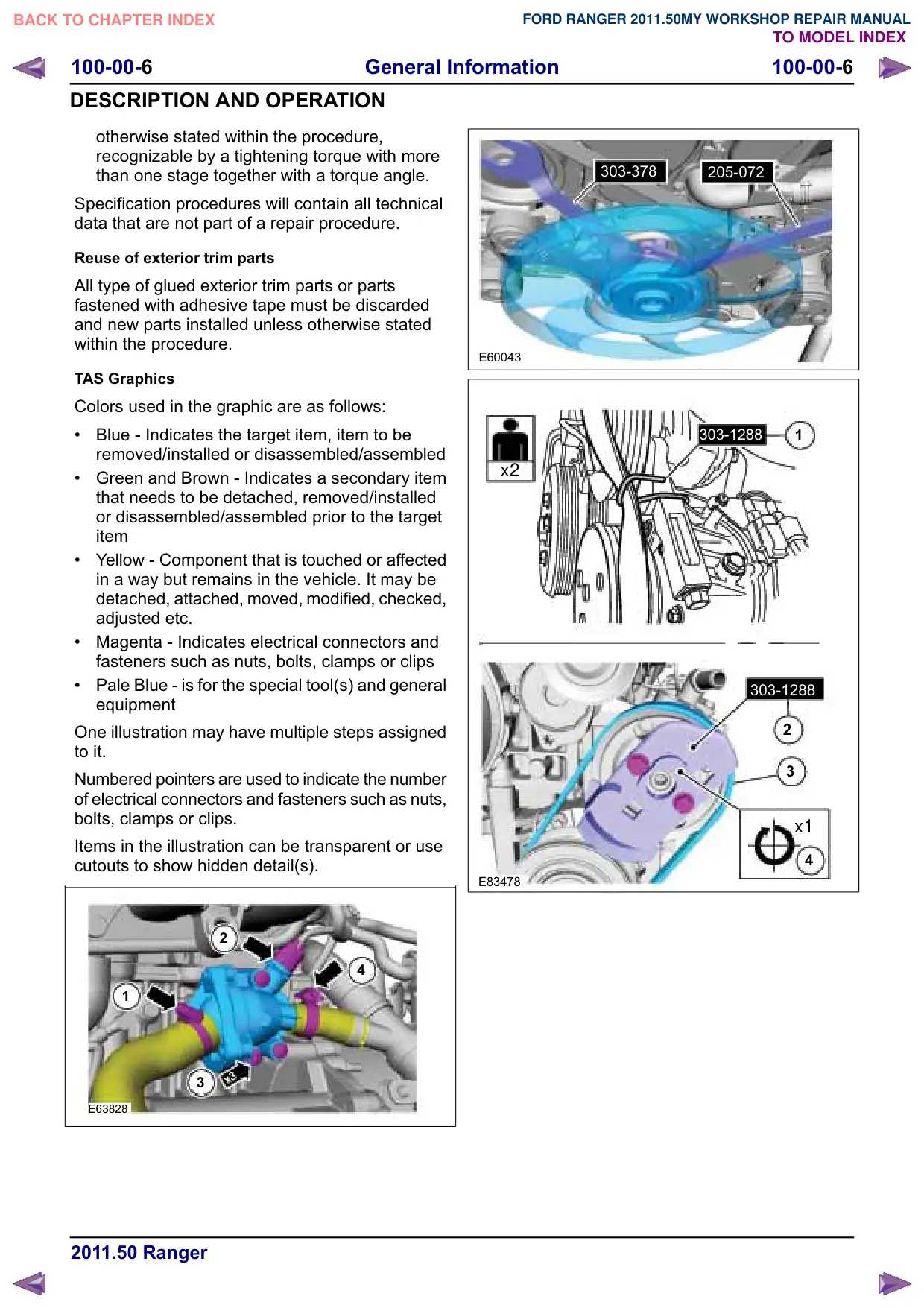
TAS Graphics
Colors used in the graphic are as follows:
Blue - Indicates the target item, item to be
removed/installed or disassembled/assembled
Green and Brown - Indicates a secondary item
that needs to be detached, removed/installed
or disassembled/assembled prior to the target
item
Yellow - Component that is touched or affected
in a way but remains in the vehicle. It may be
detached, attached, moved, modified, checked,
adjusted etc.
Magenta - Indicates electrical connectors and
fasteners such as nuts, bolts, clamps or clips
Pale Blue - is for the special tool(s) and general
equipment
One illustration may have multiple steps assigned
to it.
Numbered pointers are used to indicate the number
of electrical connectors and fasteners such as nuts,
bolts, clamps or clips.
Items in the illustration can be transparent or use
cutouts to show hidden detail(s).
2
4
1
x3
3
E63828
303-378
205-072
E60043
303-1288
1
x2
303-1288
2
3
x1
4
E83478
General Information
100-00-7
100-00-7
DESCRIPTION AND OPERATION
x1
1
2
2
E92595
2
2
1
1
E85026
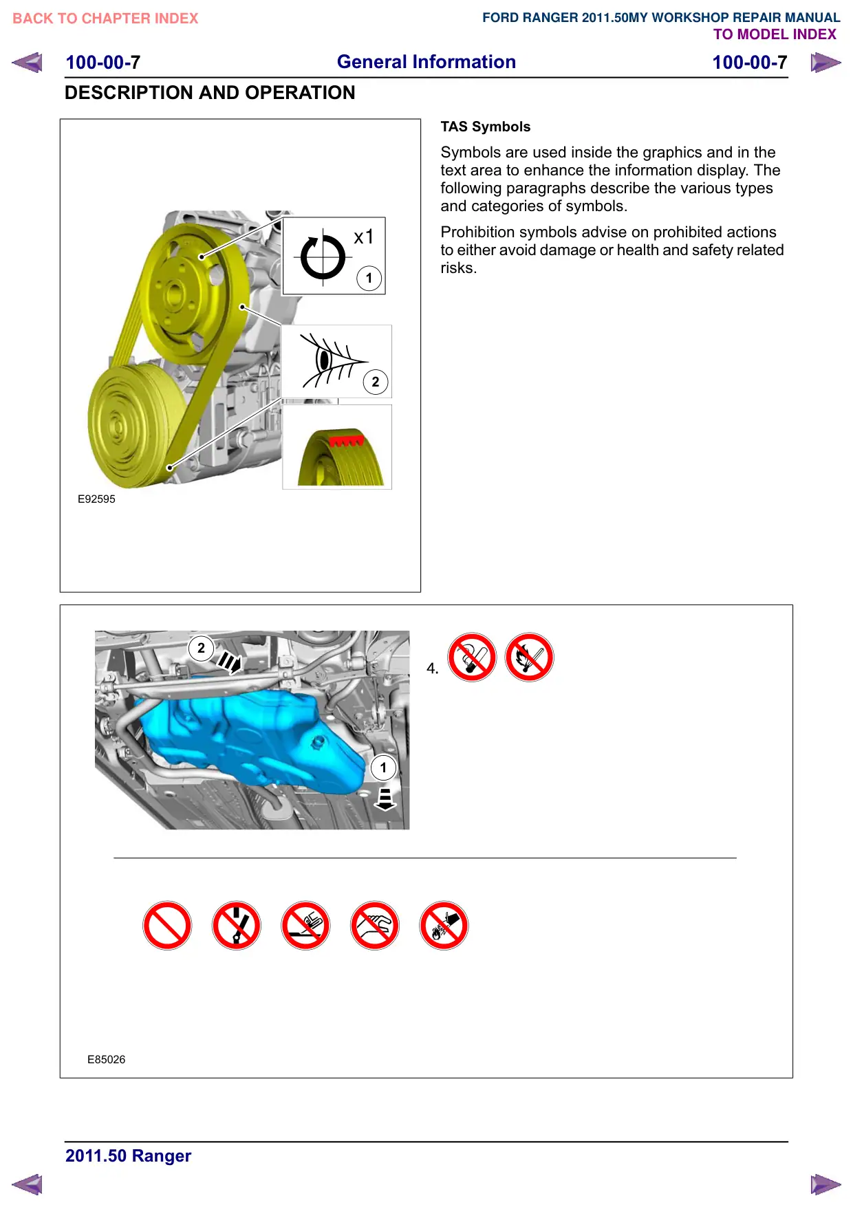
TAS Symbols
Symbols are used inside the graphics and in the
text area to enhance the information display. The
following paragraphs describe the various types
and categories of symbols.
Prohibition symbols advise on prohibited actions
to either avoid damage or health and safety related
risks.
General Information
100-00-8
100-00-8
DESCRIPTION AND OPERATION
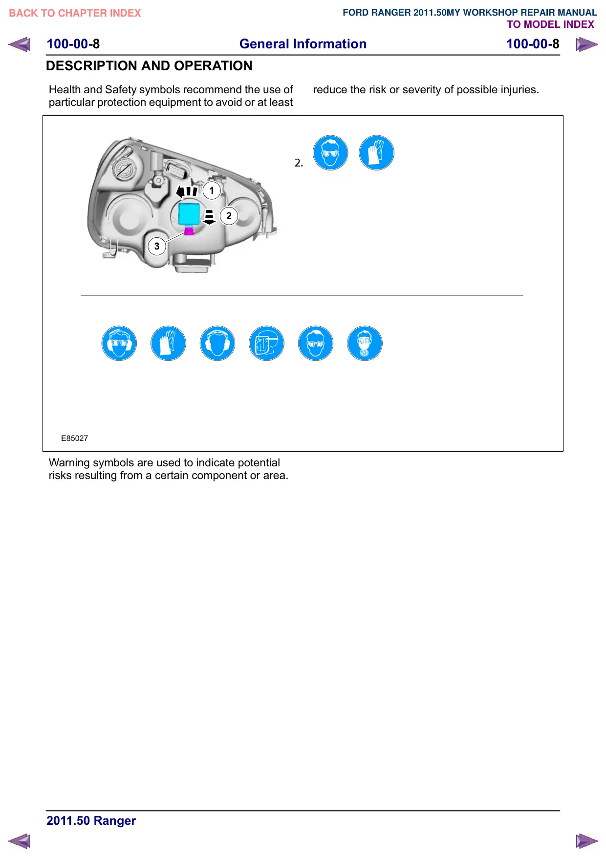
Health and Safety symbols recommend the use of
particular protection equipment to avoid or at least
1
2
3
E85027
Warning symbols are used to indicate potential
risks resulting from a certain component or area.
reduce the risk or severity of possible injuries.
General Information
100-00-
100-00-
DESCRIPTION AND OPERATION
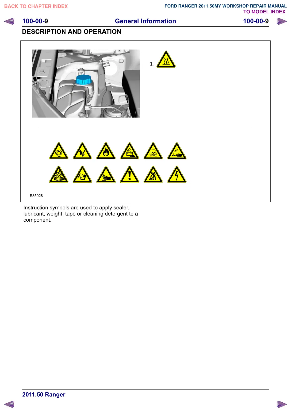
E85028
Instruction symbols are used to apply sealer,
lubricant, weight, tape or cleaning detergent to a
component.
100-00-10
General Information
100-00-10
DESCRIPTION AND OPERATION
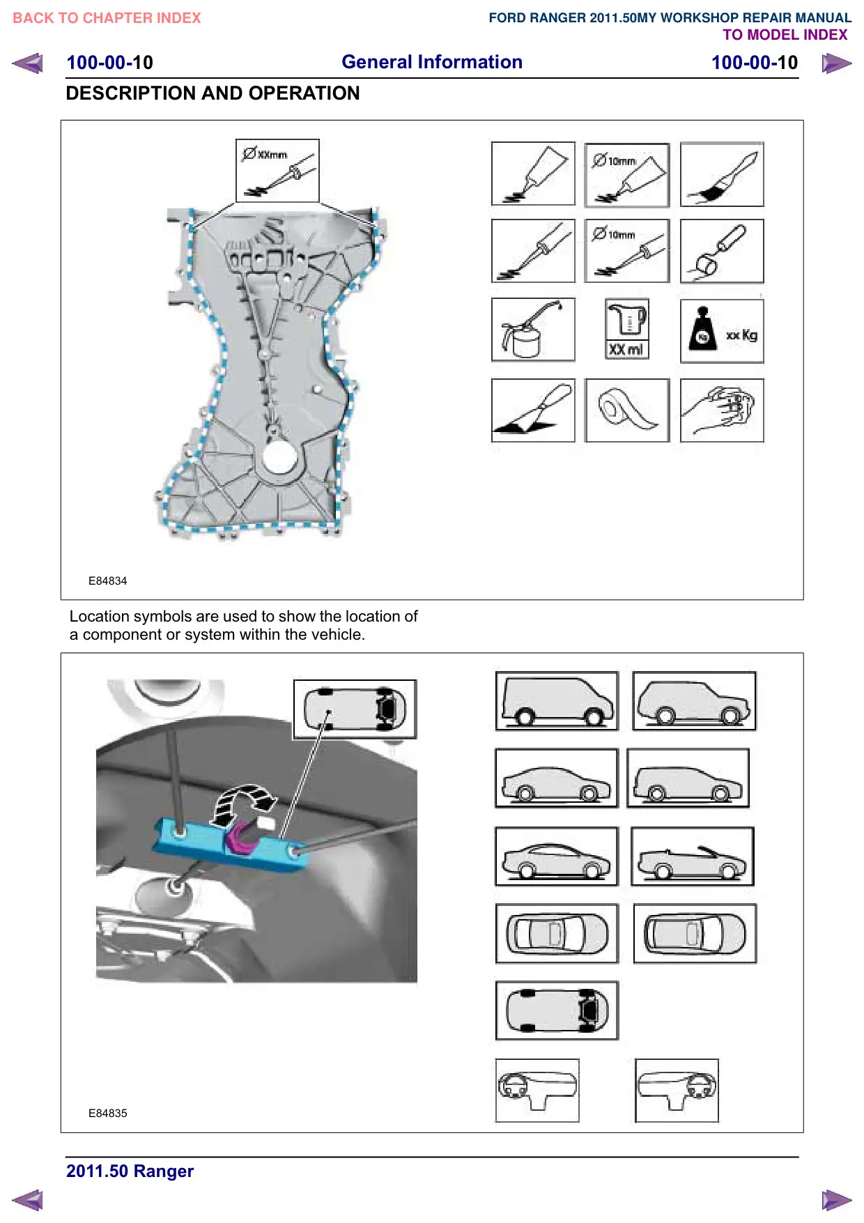
E84834
Location symbols are used to show the location of
a component or system within the vehicle.
E84835
General Information
100-00-11
100-00-11
DESCRIPTION AND OPERATION
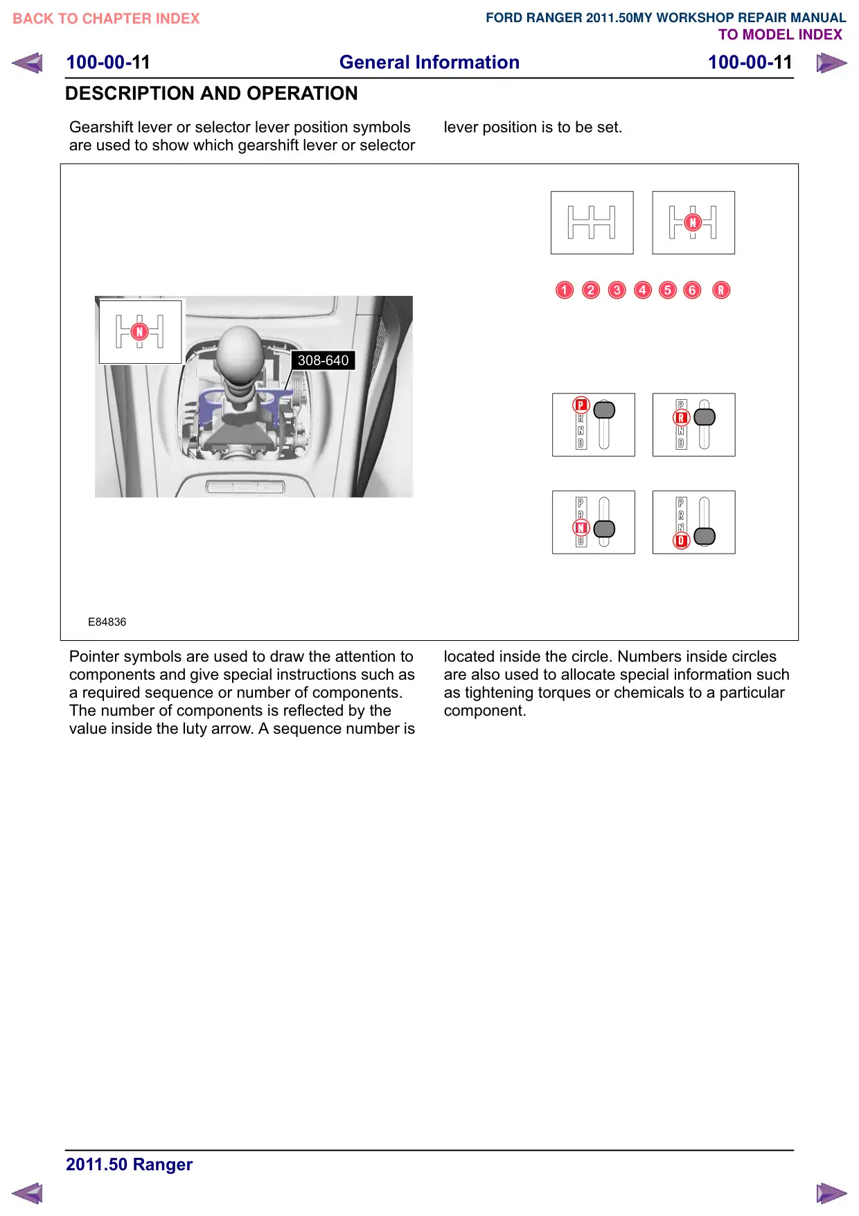
Gearshift lever or selector lever position symbols
are used to show which gearshift lever or selector
308-640
E84836
Pointer symbols are used to draw the attention to
components and give special instructions such as
a required sequence or number of components.
The number of components is reflected by the
value inside the luty arrow. A sequence number is
lever position is to be set.
located inside the circle. Numbers inside circles
are also used to allocate special information such
as tightening torques or chemicals to a particular
component.
100-00-12
General Information
100-00-12
DESCRIPTION AND OPERATION
3
2
1
x12
E84837
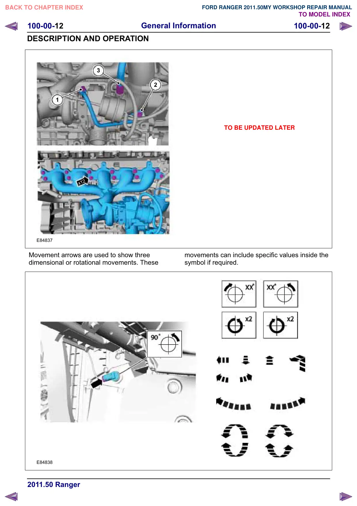
Movement arrows are used to show three
dimensional or rotational movements. These
E84838
TO BE UPDATED LATER
movements can include specific values inside the
symbol if required.
General Information
100-00-13
100-00-13
DESCRIPTION AND OPERATION
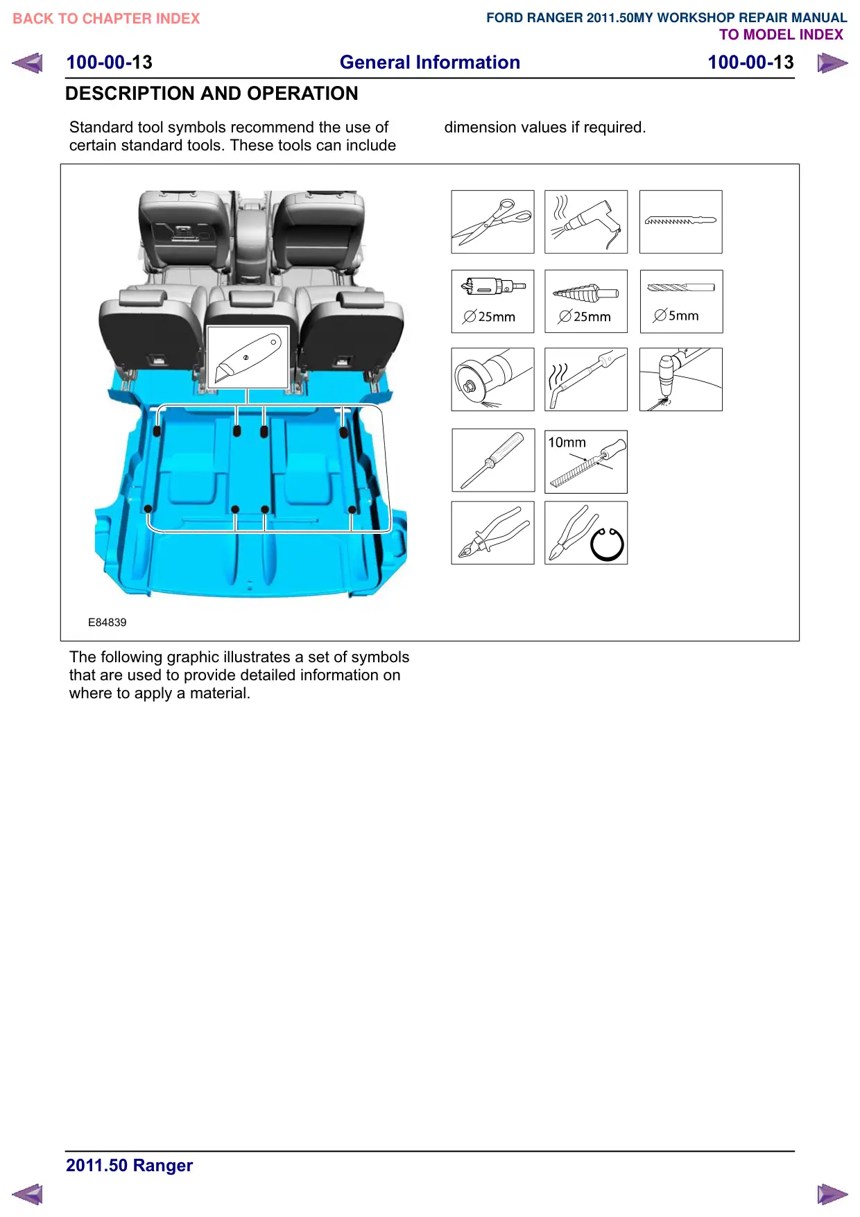
Standard tool symbols recommend the use of
certain standard tools. These tools can include
E84839
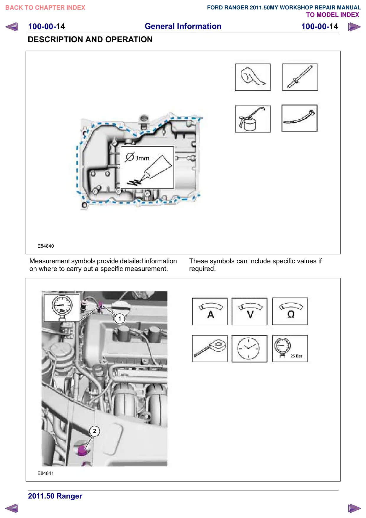
The following graphic illustrates a set of symbols
that are used to provide detailed information on
where to apply a material.
dimension values if required.
100-00-14
General Information
100-00-14
DESCRIPTION AND OPERATION
E84840
Measurement symbols provide detailed information
on where to carry out a specific measurement.
1
2
E84841
These symbols can include specific values if
required.
General Information
100-00-15
100-00-15
DESCRIPTION AND OPERATION
Special Tools and Torque Figure(s)
Special tools will be shown with the tool number
in the illustration. The special tool number(s),
general equipment, material(s) and torque figure(s)
used for the procedure step will be shown in the
text column.
How to Use This Manual - Diagnosis
and Testing procedures
This manual covers diagnosis and testing, service
and repair procedures.
This manual is structured into groups and sections,
with specific system sections collected together
under their relevant group.
A group covers a specific portion of the vehicle.
The manual is divided into five groups, General
Information, Chassis, Powertrain, Electrical and
Body and Paint. The number of the group is the
first number of a section number.
Pages at the start of the manual list all sections
available. Each section has a contents list detailing
Specifications, Description and Operation,
Diagnosis and Testing, In Vehicle Repairs,
Disassembly and Assembly, Removal and
Installation.
If components need to be removed or
disassembled in sequence, the sequence will be
identified numerically in a graphic and the
corresponding text will be numbered accordingly.
All left and right-hand references to the vehicle are
taken from a position sitting in the driver seat
looking forward.
All left and right-hand references to the engine are
taken from a position at the flywheel looking
towards the front camshaft pulley.
Where appropriate, instructions will be given for
the use of the diagnostic tool.
Inspection and Verification
Visual Inspection Charts, Symptom Charts and
other information charts (such as diagnostic
routines) or supplement test procedures with
technical specifications will navigate the user to a
specific test procedure.
Symptom Chart
The symptom chart indicates symptoms, sources
and actions to address a condition.
Pinpoint Tests
For electrical systems, pinpoint test steps are used
to identify the source of a concern in a logical,
step-by-step manner. pinpoint tests have two
columns: CONDITIONS and
DETAILS/RESULTS/ACTIONS.
The CONDITIONS column is used exclusively for
graphics and icons (with or without captions) and
the DETAILS/RESULTS/ACTIONS column
provides direction to another test step or specific
corrective actions.
The boxed numbers indicate the order in which the
described action is to be performed.
Component Tests
A component test is used when a component is
tested in multiple pinpoint tests, or if a procedure
is too complicated to be formatted within a single
page of the pinpoint test.
Graphics
Test graphics show the measurement or test to be
performed in a test step.
A representative tester graphic is used for
voltmeters and ohmmeters.
If multiple measurements are made in a single
graphic, the test leads are drawn with a solid line
until the test lead splits to indicate the multiple
measurements, at which point dashed lines are
used.
Breakout box-type testers are represented by a
double circle test pin. Test pins are labeled with
the pin number.
General Information
100-00-16
100-00-16
DESCRIPTION AND OPERATION
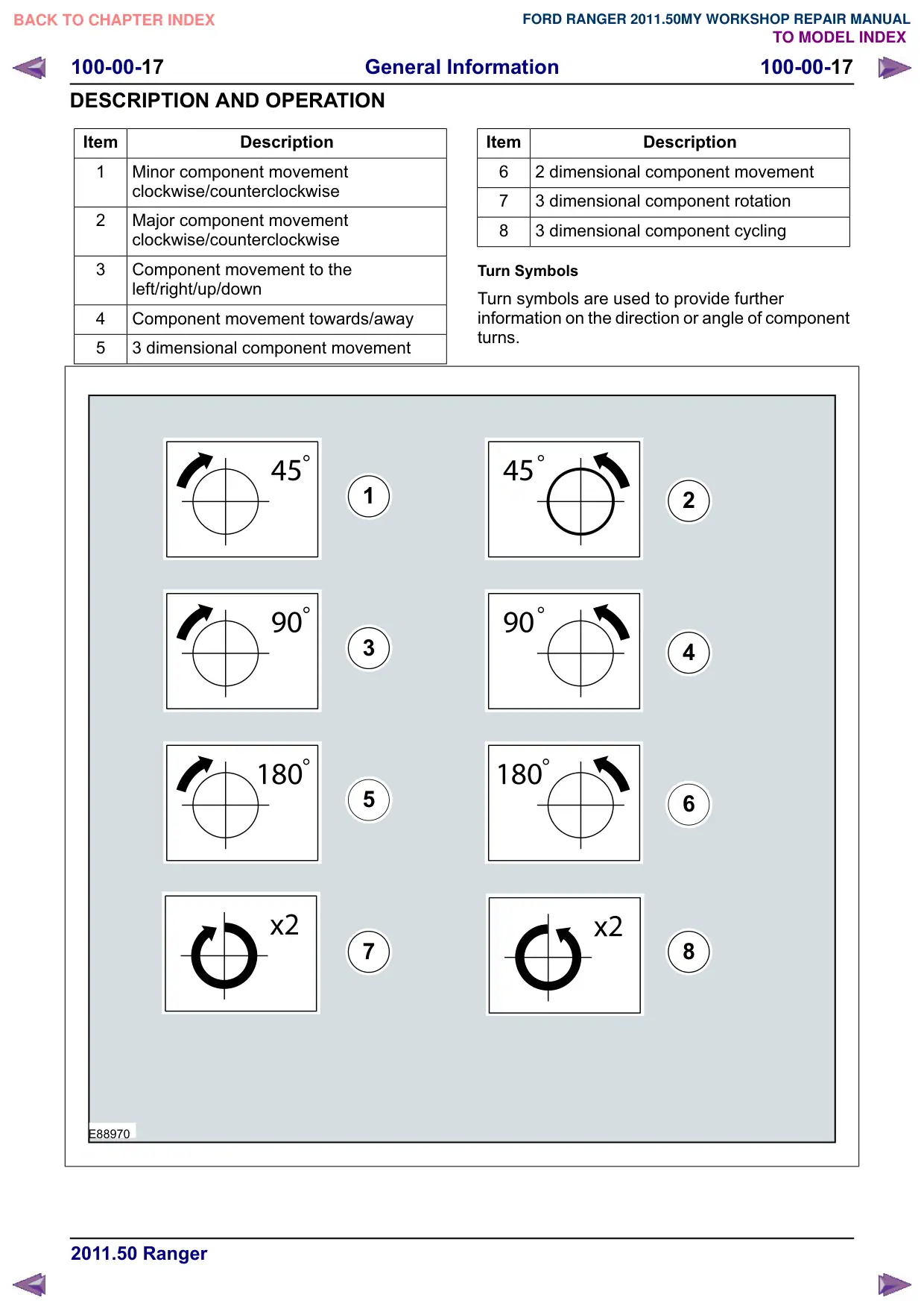
Symbols Glossary
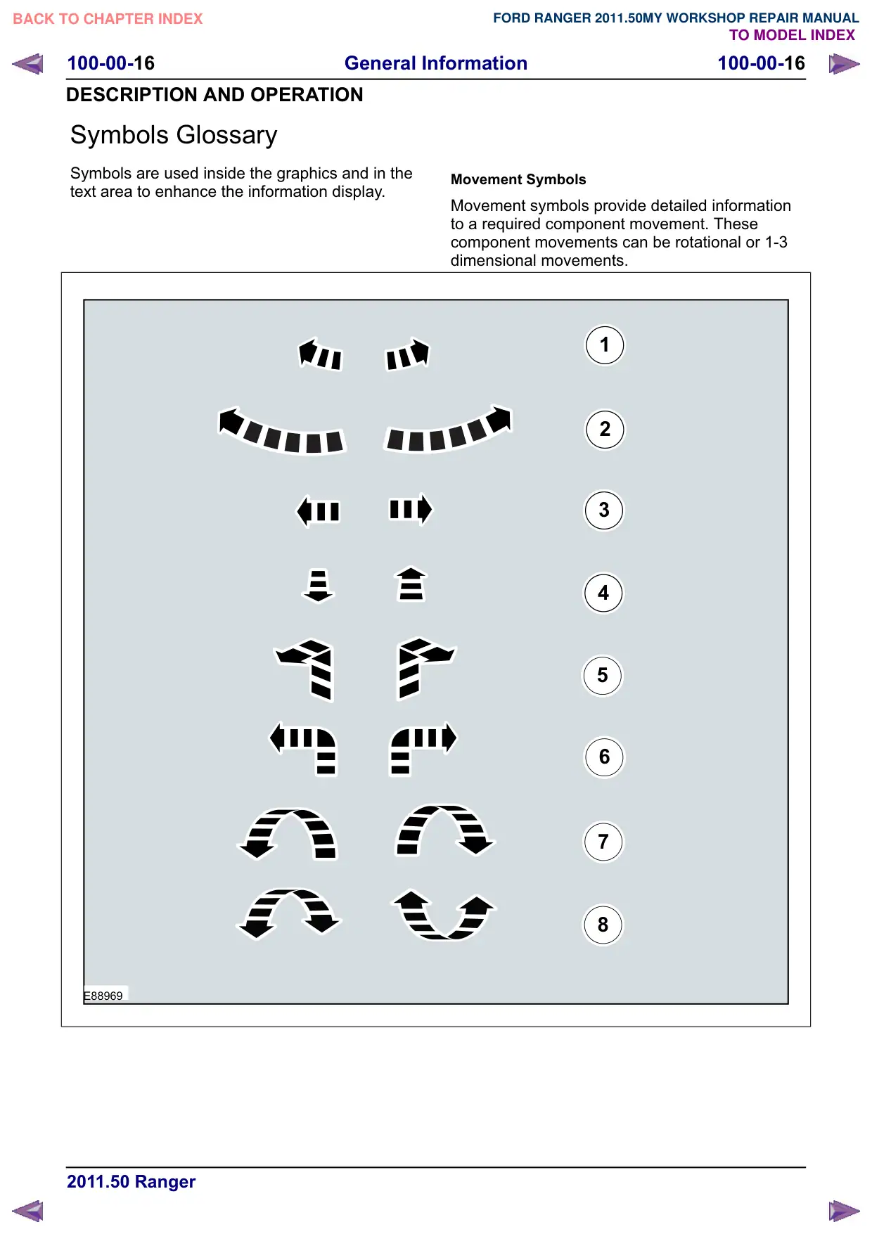
Symbols are used inside the graphics and in the
text area to enhance the information display.
E88969
Movement Symbols
Movement symbols provide detailed information
to a required component movement. These
component movements can be rotational or 1-3
dimensional movements.
1
2
3
4
5
6
7
8
General Information
100-00-17
100-00-17
DESCRIPTION AND OPERATION
Item
Description
1
Minor component movement
clockwise/counterclockwise
2
Major component movement
clockwise/counterclockwise
3
Component movement to the
left/right/up/down
4
Component movement towards/away
5
3 dimensional component movement
1
3
5
7
E88970
Item
Description
6
2 dimensional component movement
7
3 dimensional component rotation
8
3 dimensional component cycling
Turn Symbols
Turn symbols are used to provide further
information on the direction or angle of component
turns.
2
4
6
8
General Information
100-00-18
100-00-18
DESCRIPTION AND OPERATION
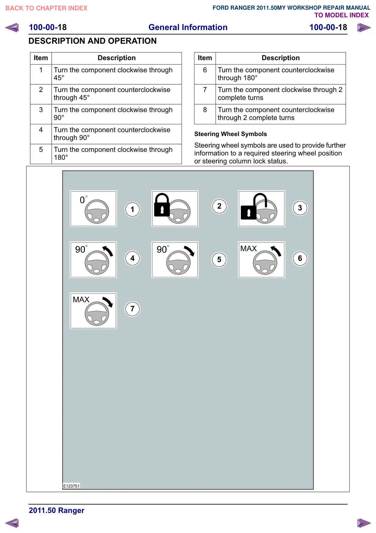
Item
Description
1
Turn the component clockwise through
45°
2
Turn the component counterclockwise
through 45°
3
Turn the component clockwise through
90°
4
Turn the component counterclockwise
through 90°
5
Turn the component clockwise through
180°
1
4
7
E123751
Item
Description
6
Turn the component counterclockwise
through 180°
7
Turn the component clockwise through 2
complete turns
8
Turn the component counterclockwise
through 2 complete turns
Steering Wheel Symbols
Steering wheel symbols are used to provide further
information to a required steering wheel position
or steering column lock status.
2
3
6
5
General Information
100-00-19
100-00-19
DESCRIPTION AND OPERATION
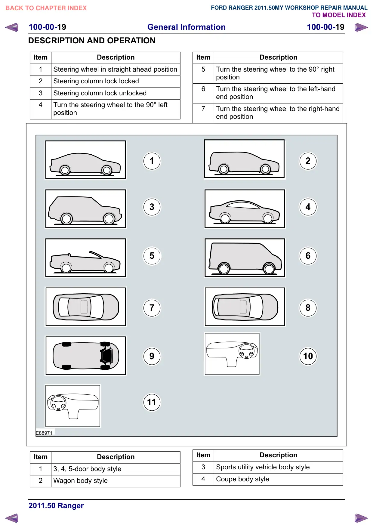
Item
Description
1
Steering wheel in straight ahead position
2
Steering column lock locked
3
Steering column lock unlocked
4
Turn the steering wheel to the 90° left
position
1
3
5
7
11
E88971
Item
Description
1
3, 4, 5-door body style
2
Wagon body style
Item
Description
5
Turn the steering wheel to the 90° right
position
6
Turn the steering wheel to the left-hand
end position
7
Turn the steering wheel to the right-hand
end position
2
4
6
8
10
Item
Description
3
Sports utility vehicle body style
4
Coupe body style
General Information
100-00-20
100-00-20
DESCRIPTION AND OPERATION
Item
Description
5
Convertible body style
6
Van body style
7
3, 4, 5-door body style - Top View
8
Wagon body style - Top View
Underview
1
4
7
E88972
Item
Description
10
Right-hand drive (RHD) vehicle
11
Left-hand drive (LHD) vehicle
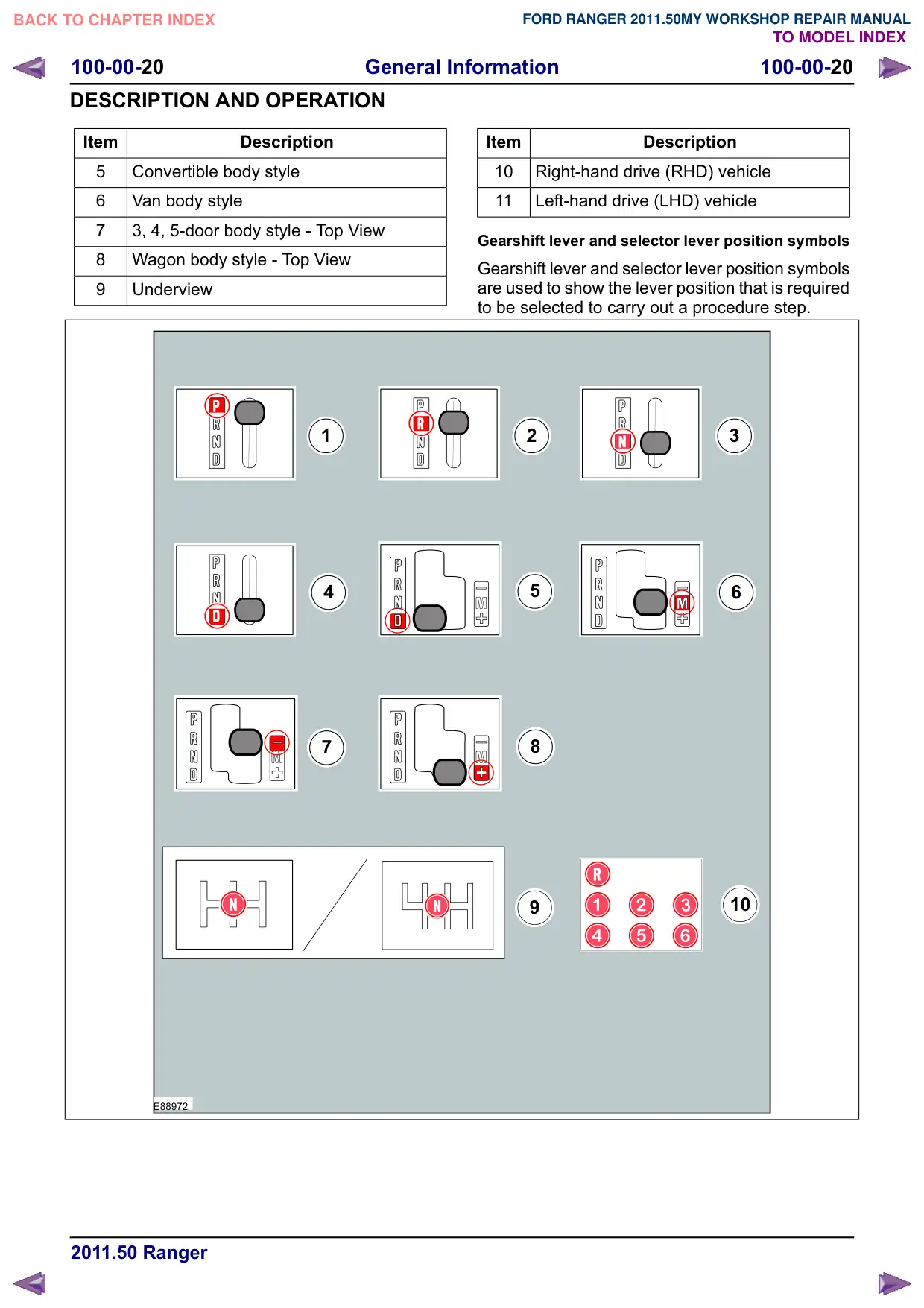
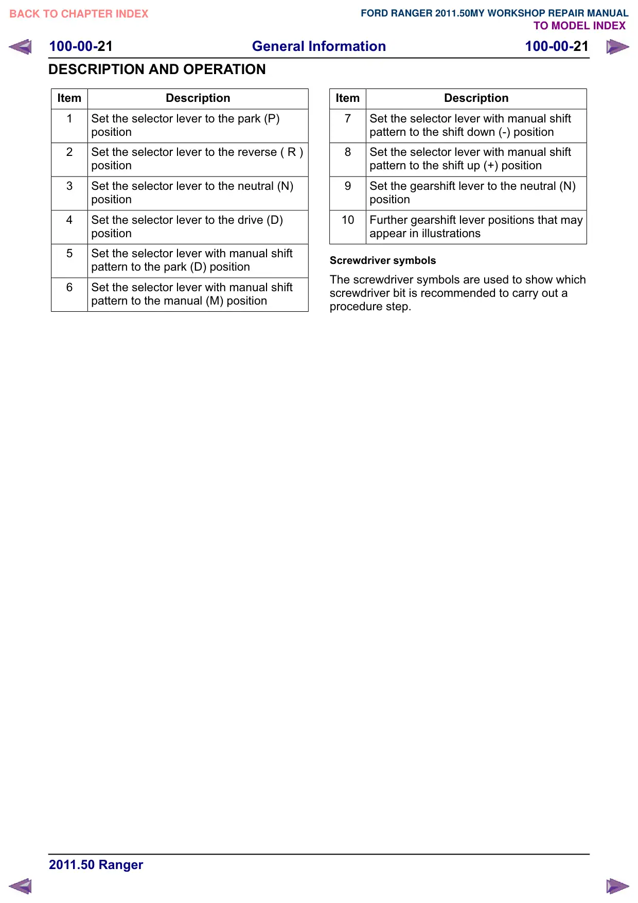
Gearshift lever and selector lever position symbols
Gearshift lever and selector lever position symbols
are used to show the lever position that is required
to be selected to carry out a procedure step.
2
3
5
6
8
10
General Information
100-00-21
100-00-21
DESCRIPTION AND OPERATION
Item
Description
1
Set the selector lever to the park (P)
position
2
Set the selector lever to the reverse ( R )
position
3
Set the selector lever to the neutral (N)
position
4
Set the selector lever to the drive (D)
position
5
Set the selector lever with manual shift
pattern to the park (D) position
6
Set the selector lever with manual shift
pattern to the manual (M) position
Item
Description
7
Set the selector lever with manual shift
pattern to the shift down (-) position
8
Set the selector lever with manual shift
pattern to the shift up (+) position
Set the gearshift lever to the neutral (N)
position
10
Further gearshift lever positions that may
appear in illustrations
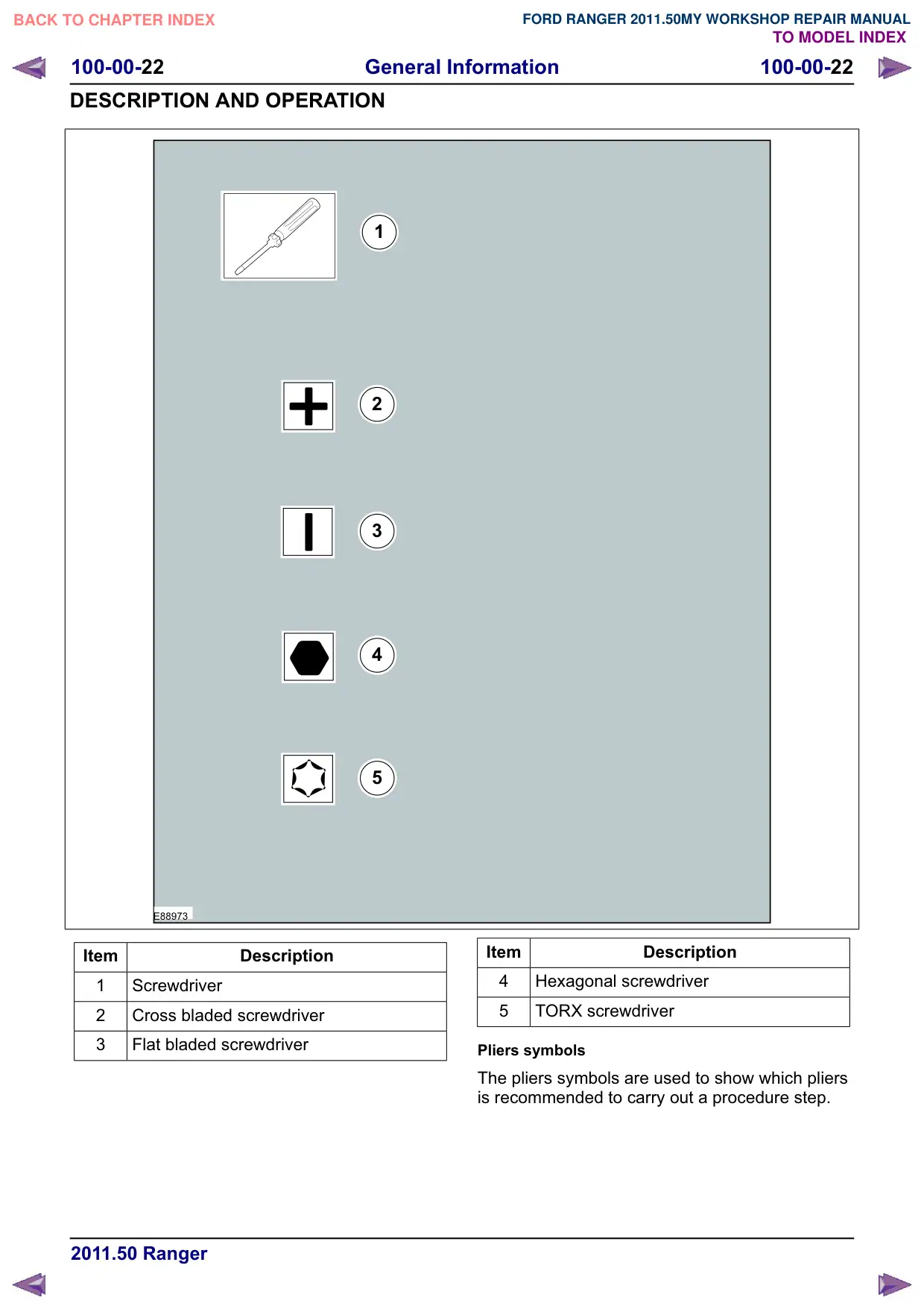
Screwdriver symbols
The screwdriver symbols are used to show which
screwdriver bit is recommended to carry out a
procedure step.
General Information
100-00-22
100-00-22
DESCRIPTION AND OPERATION
1
2
3
4
5
E88973
Item
Description
1
Screwdriver
2
Cross bladed screwdriver
3
Flat bladed screwdriver
Item
Description
4
Hexagonal screwdriver
5
TORX screwdriver
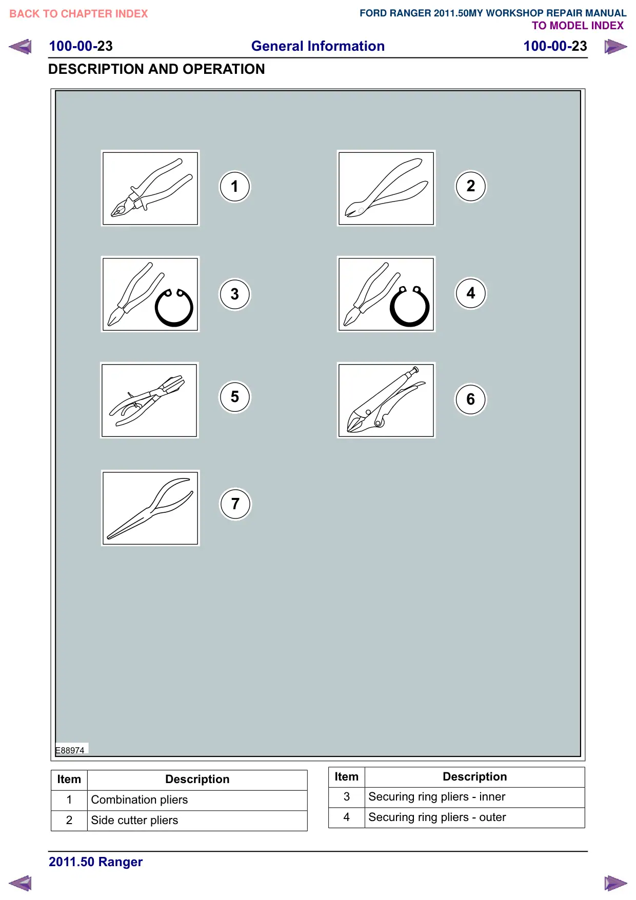
Pliers symbols
The pliers symbols are used to show which pliers
is recommended to carry out a procedure step.
General Information
100-00-24
100-00-24
DESCRIPTION AND OPERATION
Item
Description
5
Hose clamp pliers
6
Locking pliers
7
Long nose pliers
1
4
M 6
E88975
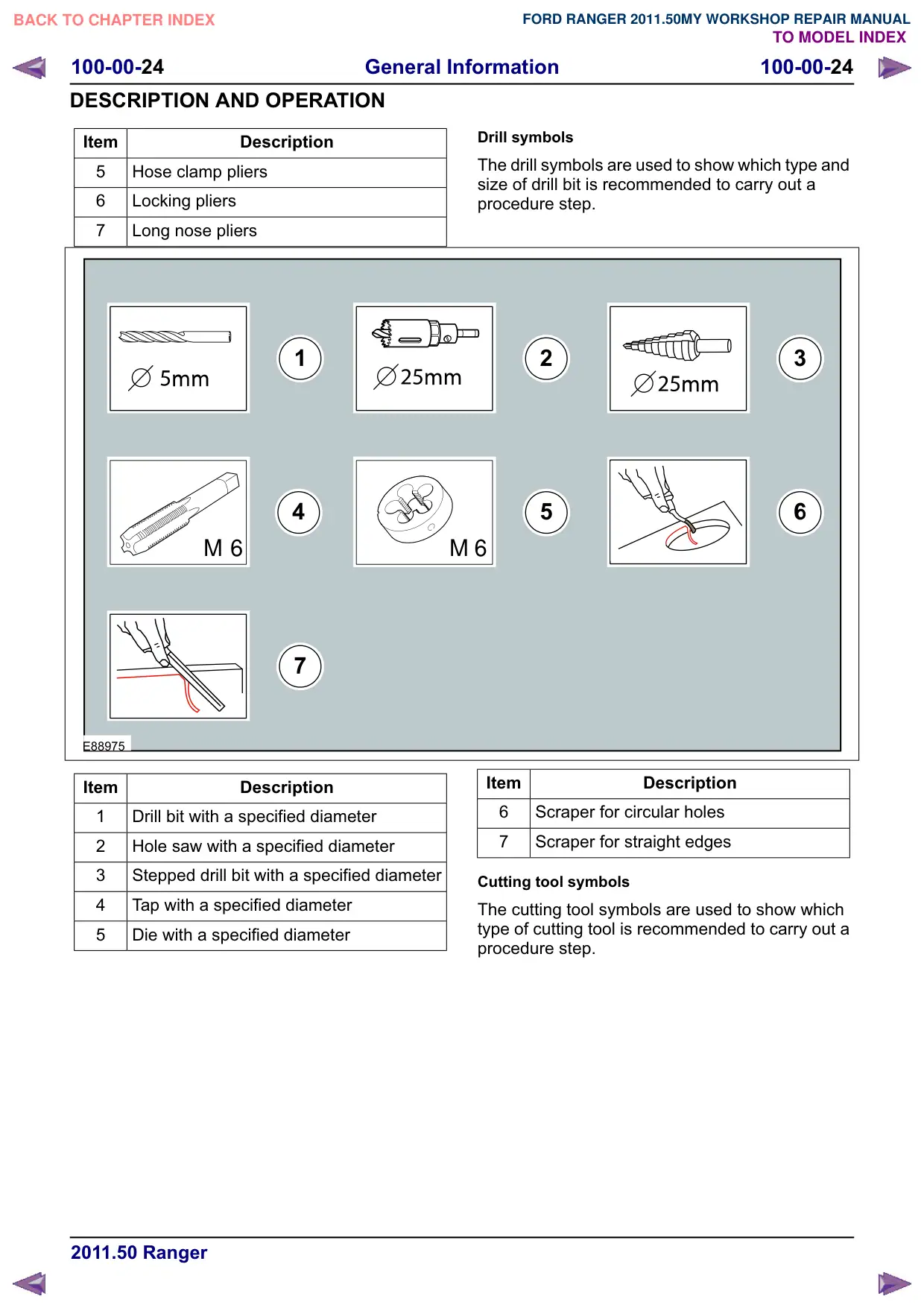
Item
Description
1
Drill bit with a specified diameter
2
Hole saw with a specified diameter
3
Stepped drill bit with a specified diameter
4
Tap with a specified diameter
5
Die with a specified diameter
Drill symbols
The drill symbols are used to show which type and
size of drill bit is recommended to carry out a
procedure step.
2
3
5
M 6
Item
Description
6
Scraper for circular holes
7
Scraper for straight edges
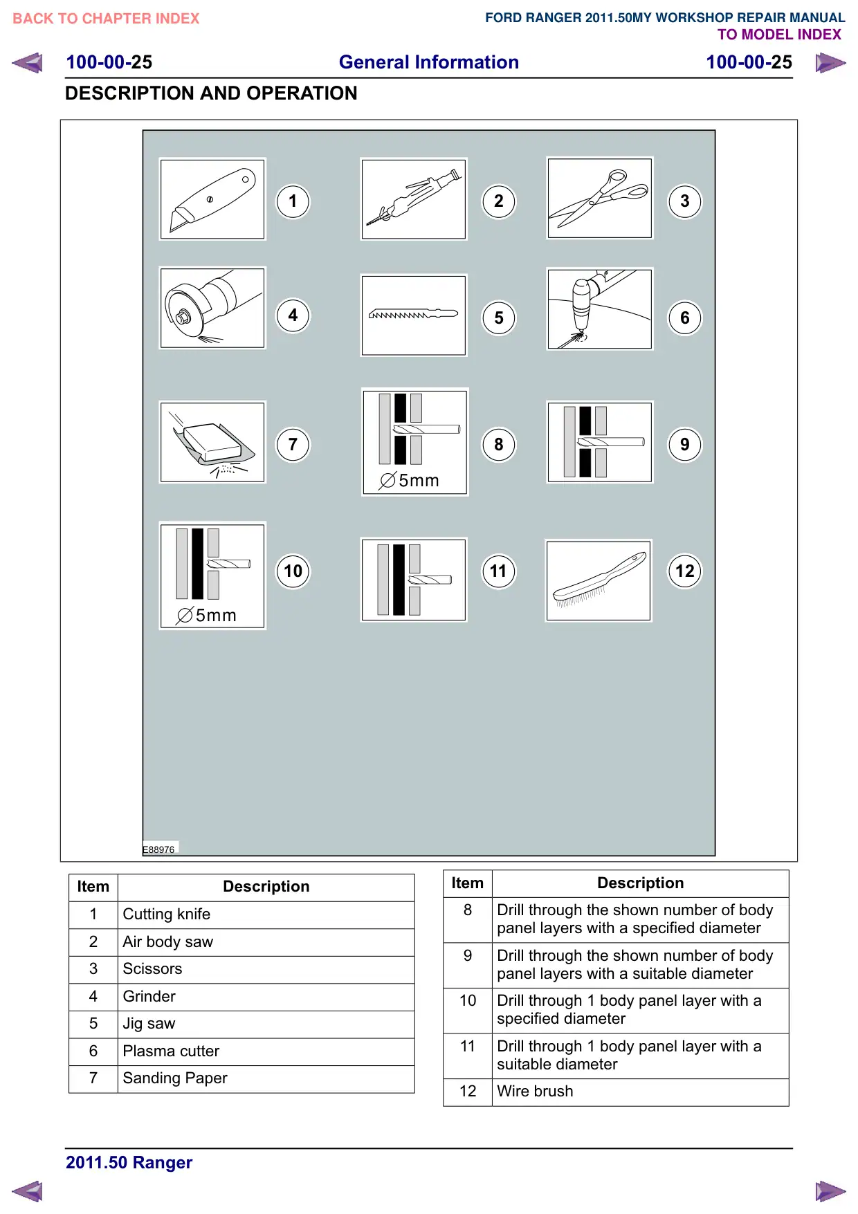
Cutting tool symbols
The cutting tool symbols are used to show which
type of cutting tool is recommended to carry out a
procedure step.
General Information
100-00-25
100-00-25
DESCRIPTION AND OPERATION
1
4
7
5mm
10
5mm
E88976
Item
Description
1
Cutting knife
2
Air body saw
3
Scissors
4
Grinder
5
Jig saw
6
Plasma cutter
7
Sanding Paper
2
3
5
6
8
11
12
Item
Description
8
Drill through the shown number of body
panel layers with a specified diameter
Drill through the shown number of body
panel layers with a suitable diameter
10
Drill through 1 body panel layer with a
specified diameter
11
Drill through 1 body panel layer with a
suitable diameter
12
Wire brush
General Information
100-00-26
100-00-26
DESCRIPTION AND OPERATION
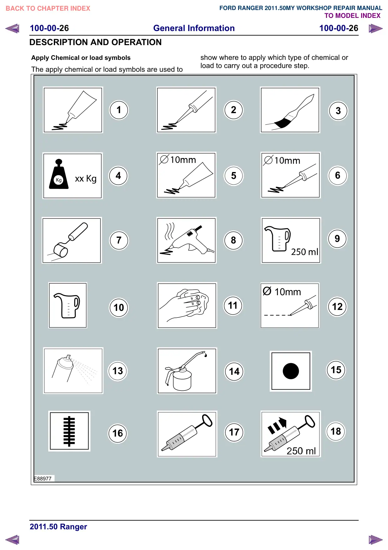
Apply Chemical or load symbols
The apply chemical or load symbols are used to
1
4
7
10
13
E88977
show where to apply which type of chemical or
load to carry out a procedure step.
2
3
6
5
8
10mm
12
14
18
General Information
100-00-27
100-00-27
DESCRIPTION AND OPERATION
Item
Description
1
Apply the substance from the specified
tube
2
Apply the substance from the specified
cartridge
3
Apply the specified chemical with a brush
4
Apply the specified load to the specified
component
5
Apply a bead with a specific diameter from
the specified tube
6
Apply a bead with a specific diameter from
the specified cartridge
7
Apply the specified chemical with a roller
8
Apply hot glue to the specified component
Apply the specified amount of fluid from
the fluid can
10
Apply fluid from the fluid can
11
Clean the specified component with the
specified material
Item
Description
12
Apply a broken bead from the specified
tube
13
Apply the specified chemical from a spray
can
14
Apply the specified lubricant to the
specified component
15
Apply spot welds to the specified
component
16
Apply a continuous weld to the specified
component
17
Handle the fluid using a syringe
18
Extract the specified amount of fluid using
a syringe
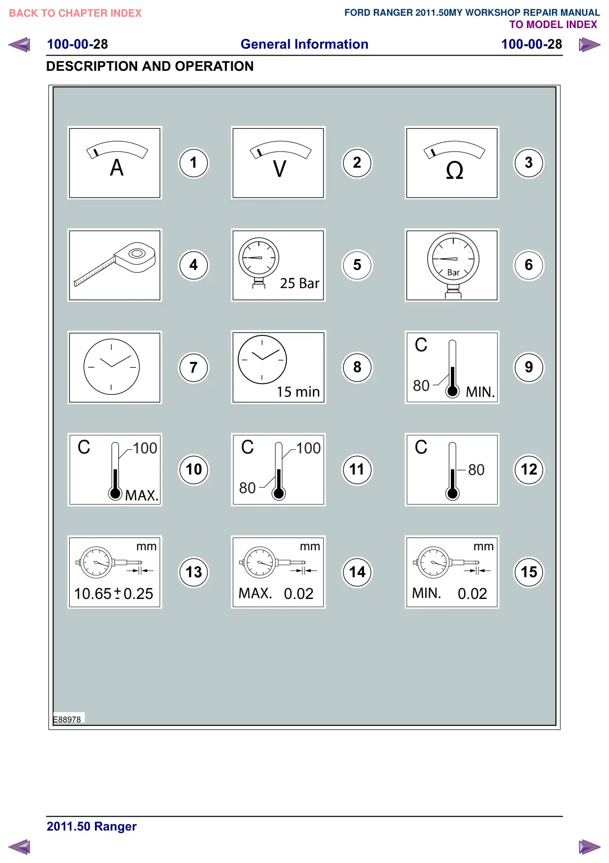
Measurement symbols
The measurement symbols are used to show
where to measure which type of measurement to
carry out a procedure step.
General Information
100-00-28
100-00-28
DESCRIPTION AND OPERATION
1
4
7
C
C
100
10
80
mm
+-
10.65 0.25
0.02
E88978
2
3
5
6
C
8
80
C
100
11
80
12
mm
mm
0.02
General Information
100-00-29
100-00-29
DESCRIPTION AND OPERATION
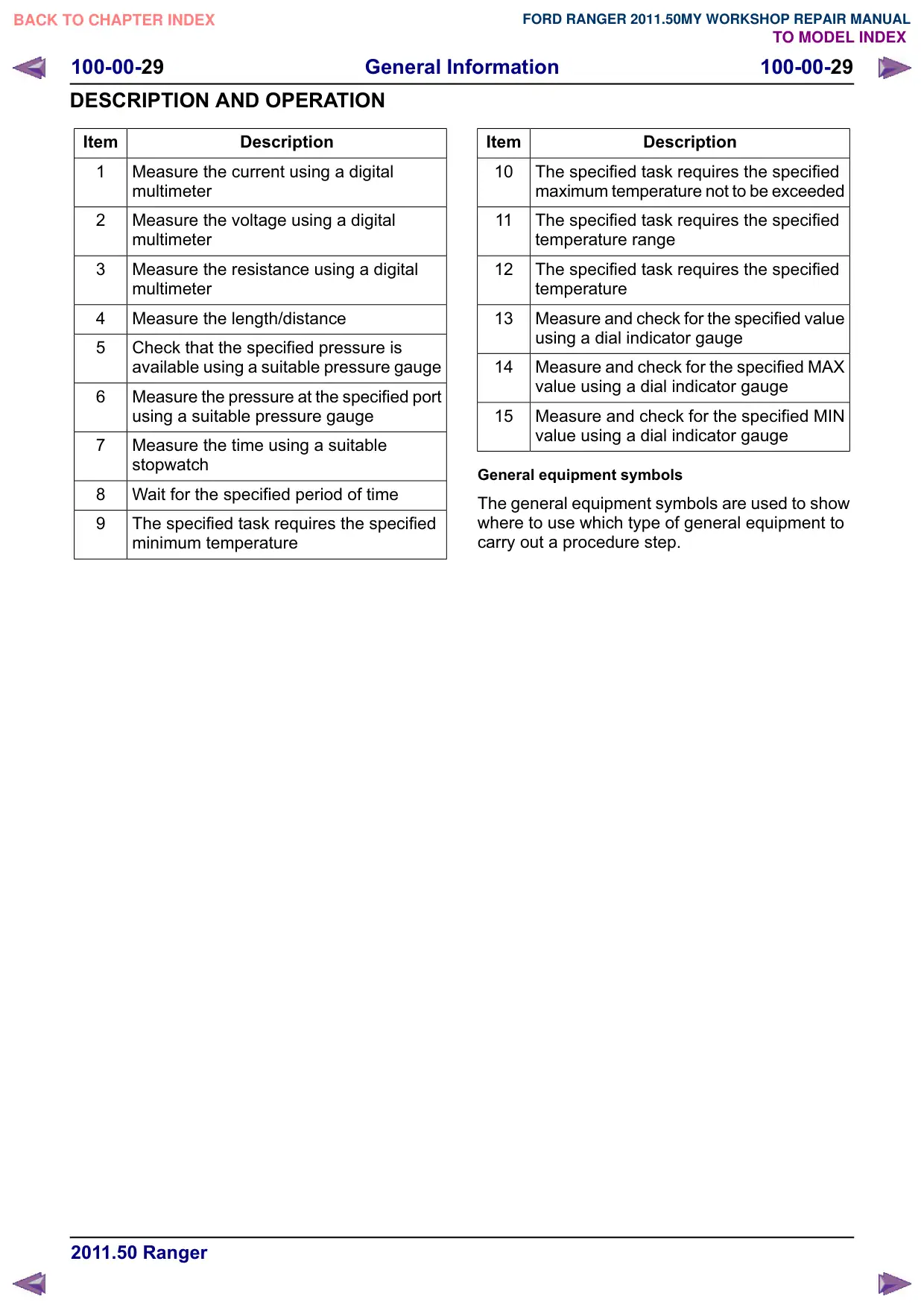
Item
Description
1
Measure the current using a digital
PXOWLPHWHU
2
Measure the voltage using a digital
PXOWLPHWHU
3
Measure the resistance using a digital
PXOWLPHWHU
4
Measure the length/distance
5
Check that the specified pressure is
available using a suitable pressure gauge
6
Measure the pressure at the specified port
using a suitable pressure gauge
7
Measure the time using a suitable
VWRSZDWFK
8
Wait for the specified period of time
The specified task requires the specified
minimum temperature
Item
Description
10
The specified task requires the specified
maximum temperature not to be exceeded
11
The specified task requires the specified
temperature range
12
The specified task requires the specified
temperature
13
Measure and check for the specified value
using a dial indicator gauge
14
Measure and check for the specified MAX
value using a dial indicator gauge
15
Measure and check for the specified MIN
value using a dial indicator gauge
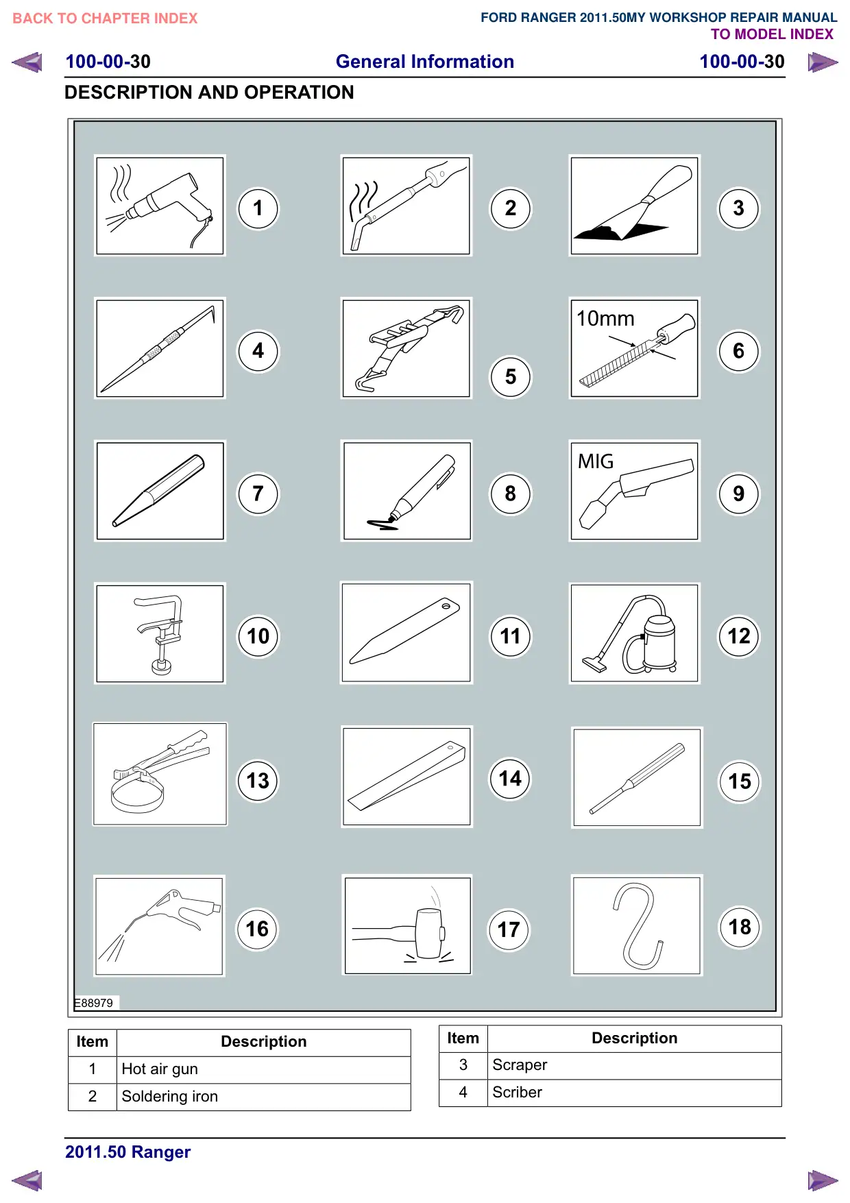
General equipment symbols
The general equipment symbols are used to show
where to use which type of general equipment to
carry out a procedure step.
General Information
100-00-30
100-00-30
DESCRIPTION AND OPERATION
1
4
E88979
Item
Description
1
Hot air gun
2
Soldering iron
2
3
Item
Description
3
Scraper
4
Scriber
General Information
100-00-31
100-00-31
DESCRIPTION AND OPERATION
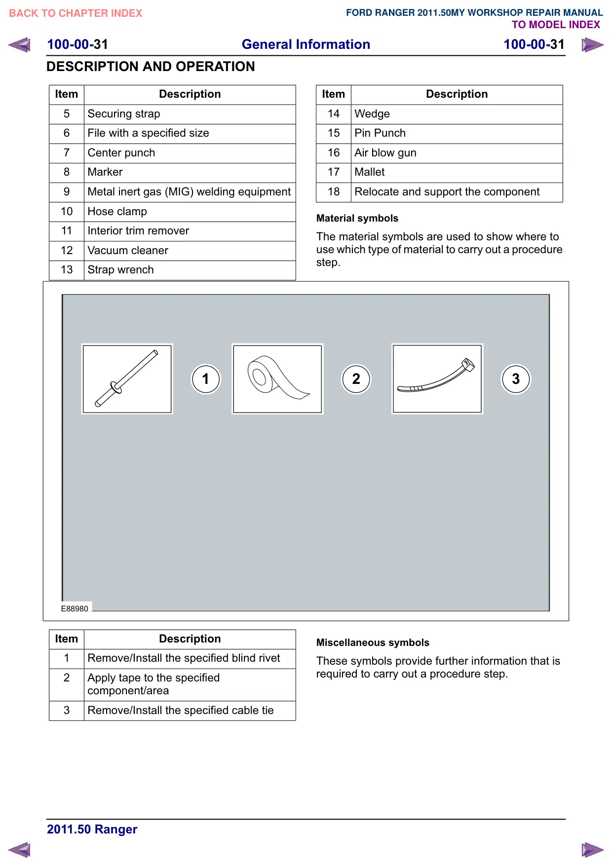
Item
Description
5
Securing strap
6
File with a specified size
7
Center punch
8
Marker
Metal inert gas (MIG) welding equipment
10
Hose clamp
11
Interior trim remover
12
Vacuum cleaner
13
Strap wrench
1
E88980
Item
Description
1
Remove/Install the specified blind rivet
2
Apply tape to the specified
component/area
3
Remove/Install the specified cable tie
Item
Description
14
Wedge
15
Pin Punch
16
Air blow gun
17
Mallet
18
Relocate and support the component
Material symbols
The material symbols are used to show where to
use which type of material to carry out a procedure
step.
2
3
Miscellaneous symbols
These symbols provide further information that is
required to carry out a procedure step.
General Information
100-00-32
100-00-32
DESCRIPTION AND OPERATION
1
4
7
13
E88981
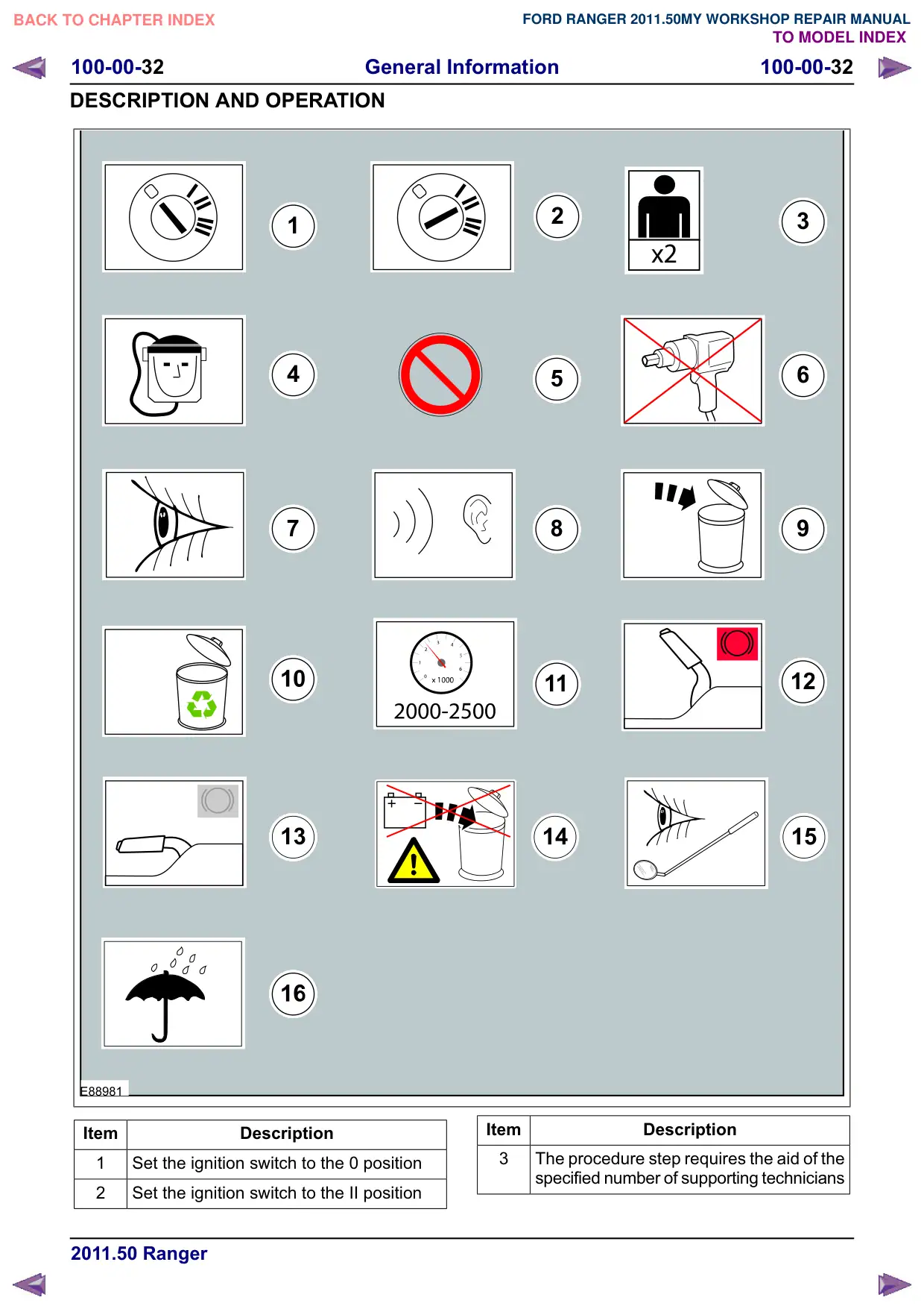
Item
Description
1
Set the ignition switch to the 0 position
2
Set the ignition switch to the II position
2
3
6
5
8
12
11
Item
Description
3
The procedure step requires the aid of the
specified number of supporting technicians
General Information
100-00-33
100-00-33
DESCRIPTION AND OPERATION
Item
Description
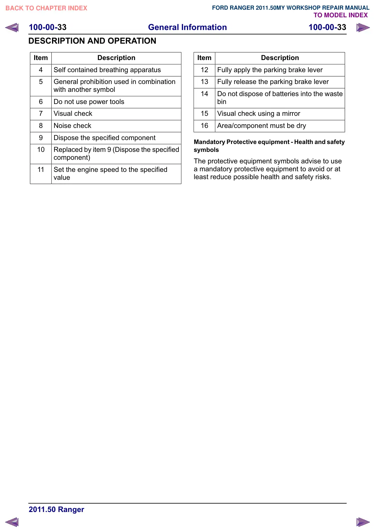
4
Self contained breathing apparatus
5
General prohibition used in combination
with another symbol
6
Do not use power tools
7
Visual check
8
Noise check
Dispose the specified component
10
Replaced by item 9 (Dispose the specified
component)
11
Set the engine speed to the specified
value
Item
Description
12
Fully apply the parking brake lever
13
Fully release the parking brake lever
14
Do not dispose of batteries into the waste
bin
15
Visual check using a mirror
16
Area/component must be dry
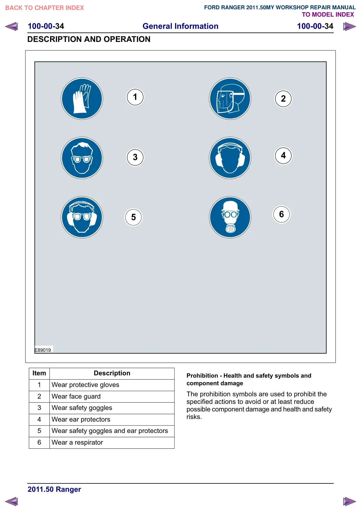
Mandatory Protective equipment - Health and safety
symbols
The protective equipment symbols advise to use
a mandatory protective equipment to avoid or at
least reduce possible health and safety risks.
General Information
100-00-34
100-00-34
DESCRIPTION AND OPERATION
1
3
5
E89019
Item
Description
1
Wear protective gloves
2
Wear face guard
3
Wear safety goggles
4
Wear ear protectors
5
Wear safety goggles and ear protectors
6
Wear a respirator
2
4
6
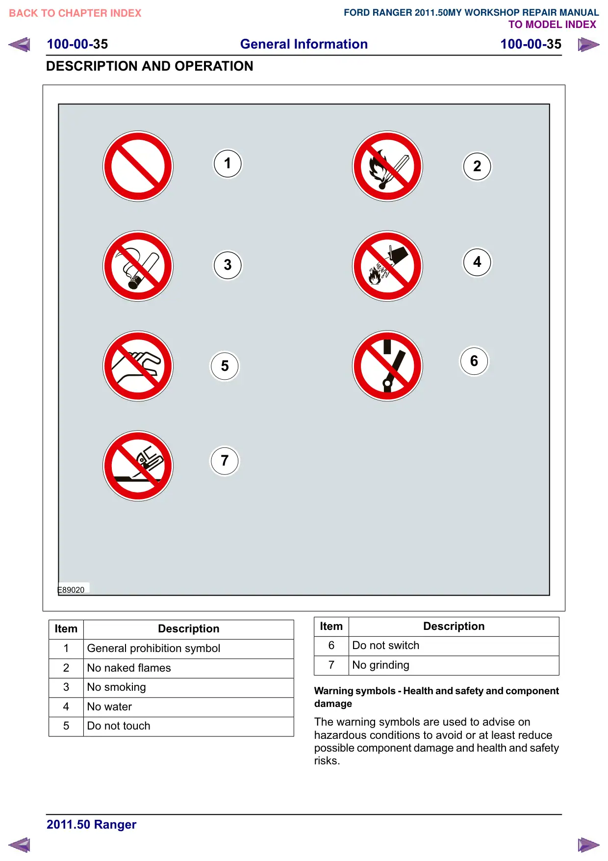
Prohibition - Health and safety symbols and
component damage
The prohibition symbols are used to prohibit the
specified actions to avoid or at least reduce
possible component damage and health and safety
risks.
General Information
100-00-35
100-00-35
DESCRIPTION AND OPERATION
1
3
5
7
E89020
Item
Description
1
General prohibition symbol
2
No naked flames
3
No smoking
4
No water
5
Do not touch
2
4
6
Item
Description
6
Do not switch
7
No grinding
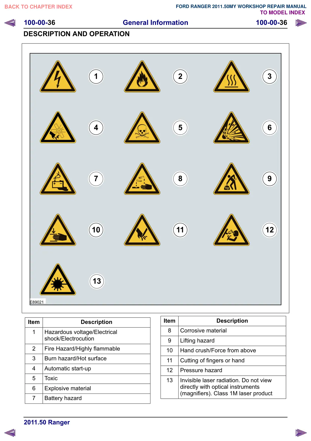
Warning symbols - Health and safety and component
damage
The warning symbols are used to advise on
hazardous conditions to avoid or at least reduce
possible component damage and health and safety
risks.
General Information
100-00-37
100-00-37
DESCRIPTION AND OPERATION
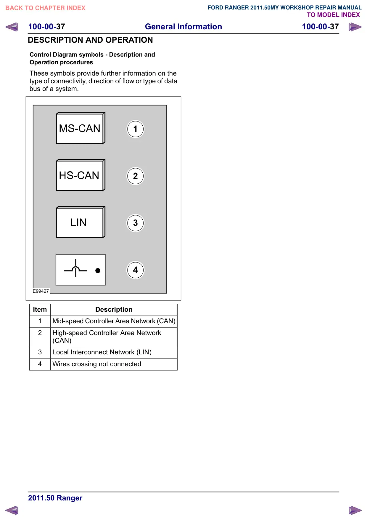
Control Diagram symbols - Description and
Operation procedures
These symbols provide further information on the
type of connectivity, direction of flow or type of data
bus of a system.
1
2
3
4
E99427
Item
Description
1
Mid-speed Controller Area Network (CAN)
2
High-speed Controller Area Network
(CAN)
3
Local Interconnect Network (LIN)
4
Wires crossing not connected
General Information
100-00-38
100-00-38
DESCRIPTION AND OPERATION
Health and Safety Precautions
Introduction
Many of the procedures associated with vehicle
maintenance and repair involve physical hazards
or other risks to health. This subsection lists,
alphabetically, some of these hazardous operations
and the materials and equipment associated with
them. Precautions necessary to avoid these
hazards are identified.
The list is not exhaustive and all operations and
procedures, and the handling of materials, should
be carried out with health and safety in mind.
Before using any product the Materials Safety Data
Sheet supplied by the manufacturer or supplier
should be consulted.
Acids and Alkalis
See also Battery Acids.
For example caustic soda, sulphuric acid.
Used in batteries and cleaning materials.
Irritant and corrosive to the skin, eyes, nose and
throat. Cause burns. Can destroy ordinary
protective clothing.
Avoid splashes to the skin, eyes and clothing. Wear
suitable protective impervious apron, gloves and
goggles. Do not breath mists.
Make sure access to eye wash bottles, shower and
soap are readily available for splashing accidents.
Display Eye Hazard sign.
Air Bags
See also Fire, Chemical Materials.
Highly flammable, explosive œ observe No Smoking
policy.
Used as a safety restraint system mounted in the
steering wheel and passenger side of the
instrument panel.
The inflator contains a high-energetic propellant
which, when ignited, produces a VERY HOT GAS
(2500°C).
The gas generant used in air bags is Sodium Azide.
This material is hermetically sealed in the module
and is completely consumed during deployment.
No attempt should be made to open an air bag
inflator as this will lead to the risk of exposure to
Sodium Azide. If a gas generator is ruptured, full
protective clothing should be worn when dealing
with the spillage.
After normal deployment, gloves and safety
goggles must be worn during the handling process.
Deployed air bags should be disposed of in a
plastic bag in accordance with local regulations at
an approved chemical waste site.
Following any direct contact with gas generant.
œ wash affected areas thoroughly with water.
œ seek medical assistance if necessary.
Air Bags - Do's
œ Do store modules in an upright position.
œ Do keep modules dry.
œ Do carry modules with the cover side pointing
away from the body.
œ Do place modules with their cover side upwards.
œ Do carefully inspect modules for damage.
œ Do stand to one side when connecting modules.
œ Do make sure all test equipment is properly
calibrated and maintained.
œ Do wash hands after handling deployed air
bags.
Air Bags - Do Nots
œ Do not store highly flammable material together
with modules or gas generators.
œ Do not store gas generators at temperatures
exceeding 80°C.
œ Do not store modules upside down.
œ Do not attempt to open a gas generator housing.
œ Do not expose gas generators to open flame or
sources of heat.
œ Do not place anything on top of a module cover.
œ Do not use damaged modules.
œ Do not touch a fired module or gas generator
for at least 10 minutes.
œ Do not use any electrical probes on the wiring
circuit.
Air Conditioning Refrigerant
See also Chlorofluorocarbon, Chemical Materials
Highly flammable, combustible œ observe No
Smoking policy.
General Information
100-00-39
100-00-39
DESCRIPTION AND OPERATION
Skin contact may result in frostbite.
Instructions given by the manufacturer must be
followed. Avoid naked lights, wear suitable
protective gloves and goggles.
If refrigerant comes into contact with the skin or
eyes, immediately rinse the affected areas with
water. Eyes should also be rinsed with an
appropriate irrigation solution and should not be
rubbed. SEEK MEDICAL ASSISTANCE IF
NECESSARY.
Air Conditioning Refrigerant - Do Nots
œ Do not expose refrigerant bottles to sunlight or
heat.
œ Do not stand refrigerant bottles upright; when
filling, hold them with the valve downwards.
œ Do not expose refrigerant bottles to frost.
œ Do not drop refrigerant bottles.
œ Do not vent refrigerant to atmosphere under any
circumstance.
œ Do not mix refrigerants, for example R12 (Freon)
and R134a.
Adhesives and Sealers
See also Fire, Chemical Materials.
Highly flammable, flammable, combustible œ
observe No Smoking policy.
Generally should be stored in No Smoking areas.
Cleanliness and tidiness in use should be
observed, for example disposable paper covering
benches; should be dispensed from applicators
where possible; containers, including secondary
containers, should be labeled appropriately.
Solvent-based Adhesives/Sealers - See
Solvents
Follow manufacturers instructions.
Water-based Adhesives/Sealers
Those based on polymer emulsions and rubber
latexes may contain small amounts of volatile toxic
and harmful chemicals. Skin and eye contact
should be avoided and adequate ventilation
provided during use.
Hot Melt Adhesives
In the solid state, they are safe. In the molten state
they may cause burns and health hazards may
arise from the inhalation of toxic fumes.
Use appropriate protective clothing and a
thermostatically controlled heater with a thermal
cut-out and adequate extraction.
Resin-based Adhesives/Sealers, for
example Epoxide and Formaldehyde
Resin-based
Mixing should be carried out in well ventilated
areas, as harmful or toxic volatile chemicals may
be released.
Skin contact with uncured resins and hardeners
can result in irritation, dermatitis, and absorption
of toxic or harmful chemicals through the skin.
Splashes can damage the eyes.
Provide adequate ventilation and avoid skin and
eye contact.
Anaerobic, Cyanoacrylate (super-glues)
and other Acrylic Adhesives
Many are irritant, sensitizing or harmful to the skin
and respiratory tract. Some are eye irritants.
Skin and eye contact should be avoided and the
manufacturers instructions followed.
Cyanoacrylate adhesives (super-glues) MUST NOT
contact the skin or eyes. If skin or eye tissue is
bonded, cover with a clean moist pad and SEEK
IMMEDIATE MEDICAL ATTENTION. Do not
attempt to pull tissue apart. Use in well ventilated
areas as vapors can cause irritation to the nose
and eyes.
For two-pack systems see Resin-based and
Isocyanate Adhesives/Sealers.
Isocyanate (Polyurethane)
Adhesives/Sealers
See also Resin-based Adhesives.
Individuals suffering from asthma or respiratory
allergies should not work with or near these
materials as sensitivity reactions can occur.
Over exposure is irritating to the eyes and
respiratory system. Excessive concentrations may
produce effects on the nervous system including
General Information
100-00-40
100-00-40
DESCRIPTION AND OPERATION
drowsiness. In extreme cases, loss of
consciousness may result. Long term exposure to
vapor concentrations may result in adverse health
effects.
Prolonged contact with the skin may have a
defatting effect which may lead to skin irritation
and in some cases, dermatitis.
Splashes entering the eye will cause discomfort
and possible damage.
Any spraying should preferably be carried out in
exhaust ventilated booths, removing vapors and
spray droplets from the breathing zone.
Wear appropriate gloves, eye and respiratory
protection.
Antifreeze
See also Fire, Solvents.
For example isopropanol, ethylene glycol,
methanol.
Highly flammable, flammable, combustible.
Used in vehicle coolant systems, brake air pressure
systems, screenwash solutions.
Vapors may be given off from coolant antifreeze
(glycol) when heated. Avoid breathing these
vapors.
Antifreeze may be absorbed through the skin in
toxic or harmful quantities. Antifreeze, if swallowed,
can be fatal and MEDICAL ATTENTION SHOULD
BE SOUGHT IMMEDIATELY.
These products must not be used in any cooling
or industrial water system that is connected or
linked to general, food preparation or drinking water
supplies.
Asbestos
See also Warning Symbols on Vehicles at the end
of this subsection.
Breathing asbestos dust may cause lung damage
or, in some cases, cancer.
Used in brake and clutch linings, transmission
brake bands and gaskets.
The use of drum cleaning units, vacuum cleaning
or damp wiping is preferred.
Asbestos dust waste should be dampened, placed
in a sealed container and marked for safe disposal.
If any cutting or drilling is attempted on materials
containing asbestos the item should be dampened
and only hand tools or low speed power tools used.
Battery Acids
See also Acids and Alkalis.
Gases released during charging are explosive.
Never use naked flames or allow sparks near
charging or recently charged batteries.
Make sure there is adequate ventilation.
Brake and Clutch Linings and Pads
See Asbestos.
Brake Fluids (Polyalkylene Glycols)
See also Fire.
Splashes to the skin and eyes are slightly irritating.
Avoid skin and eye contact as far as possible.
Inhalation vapor hazards do not arise at ambient
temperatures because of the very low vapor
pressure.
Brazing
See Welding.
Chemical Materials
See also Legal Aspects.
Chemical materials such as solvents, sealers,
adhesives, paints, resin foams, battery acids,
antifreeze, brake fluids, fuels, oils and grease
should always be used with caution and stored and
handled with care. They may be toxic, harmful,
corrosive, irritant or highly flammable and give rise
to hazardous fumes and dusts.
The effects of excessive exposure to chemicals
may be immediate or delayed; briefly experienced
or permanent; cumulative; superficial; life
threatening; or may reduce life expectancy.
Chemical Materials - Do's
œ Do carefully read and observe hazard and
precaution warnings given on material
containers (labels) and in any accompanying
leaflets, posters or other instructions. Material
General Information
100-00-41
100-00-41
DESCRIPTION AND OPERATION
health and safety data sheets can be obtained
from manufacturers.
œ Do remove chemical materials from the skin
and clothing as soon as practicable after soiling.
Change heavily soiled clothing and have it
cleaned.
œ Do organize work practices and protective
clothing to avoid soiling of the skin and eyes;
breathing vapors, aerosols, dusts or fumes;
inadequate container labeling; fire and explosion
hazards.
œ Do wash before job breaks, before eating,
smoking, drinking or using toilet facilities when
handling chemical materials.
œ Do keep work areas clean, uncluttered and free
of spills.
œ Do store chemical materials according to
national and local regulations.
œ Do keep chemical materials out of the reach of
children.
Chemical Materials - Do Nots
œ Do not mix chemical materials except under the
manufacturers instructions; some chemicals can
form other toxic or harmful chemicals, give off
toxic or harmful fumes or become explosive
when mixed together.
œ Do not spray chemical materials, particularly
those based on solvents, in confined spaces,
for example when people are inside a vehicle.
œ Do not apply heat or flame to chemical materials
except under the manufacturers instructions.
Some are highly flammable and some may
release toxic or harmful fumes.
œ Do not leave containers open. Fumes given off
can build up to toxic, harmful or explosive
concentrations. Some fumes are heavier than
air and will accumulate in confined areas such
as pits.
œ Do not transfer chemical materials to unlabelled
containers.
œ Do not clean hands or clothing with chemicals.
Chemicals, particularly solvents and fuels, will
dry the skin and may cause irritation leading to
dermatitis or be absorbed through the skin in
toxic or harmful quantities.
œ Do not use emptied containers for other
materials except when they have been cleaned
under supervised conditions.
œ Do not sniff or smell chemical materials. Brief
exposure to high concentrations of fumes can
be toxic or harmful.
Chlorofluorocarbons (CFC)
There is concern in the scientific community that
CFCs and Halons are depleting the upper ozone
layer which filters out harmful ultraviolet radiation.
Decreased filtration of ultraviolet radiation may
result in increases in skin cancer, cataracts and
immune system suppression in humans, as well
as decreased productivity of crops and aquatic
systems.
CFCs are used primarily as refrigerants in vehicle
air conditioning systems and as aerosol
propellants. Halons are used as fire extinguishants.
Clutch Fluids
See Brake fluids.
Clutch Linings and Pads
See Asbestos.
Corrosion Protection Materials
See also Solvents, Fire.
Highly flammable, flammable œ observe No
Smoking policy.
These materials are varied and the manufacturers
instructions must be followed. They may contain
solvents, resins or petroleum products. Skin and
eye contact should be avoided. They should only
be sprayed in conditions of adequate ventilation
and not in confined spaces.
Cutting
See Welding.
Dewaxing
See Solvents and Fuels (Kerosene).
General Information
100-00-42
100-00-42
DESCRIPTION AND OPERATION
Dusts
Powder, dusts or clouds may be irritant, harmful
or toxic. Avoid breathing dusts from powdery
chemical materials or those arising from dry
abrasion operations. Wear respiratory protection
if ventilation is inadequate.
Fine dusts of combustible material can present an
explosion hazard. Avoid explosive limits and
sources of ignition.
Electric Shock
Electric shock can result from the use of faulty
electrical equipment or from the misuse of
equipment in good condition.
Make sure that electrical equipment is maintained
in good condition and frequently tested. Faulty
equipment should be labeled and preferably
removed from the workstation.
Make sure that flexes, cables, plugs and sockets
are not frayed, kinked, cut, cracked or otherwise
damaged.
Make sure that electrical equipment and flexes do
not come into contact with water.
Make sure that electrical equipment is protected
by the correct rated fuse.
Never misuse electrical equipment and never use
equipment that is in any way faulty. The results
could be fatal.
Make sure that the cables of mobile electrical
equipment cannot get trapped and damaged, such
as in a vehicle hoist.
Make sure that the designated electrical workers
are trained in basic First Aid.
In cases of electrocution:
œ switch off the power supply before approaching
the victim.
œ if this is not possible push or drag the victim
from the source of electricity using dry
non-conductive material.
œ commence resuscitation if trained to do so.
œ SUMMON MEDICAL ASSISTANCE.
Engine Oils
See Lubricants and Grease.
Exhaust Fumes
These contain asphyxiating, harmful and toxic
chemicals and particles such as carbon oxides,
nitrogen oxides, aldehydes, lead and aromatic
hydrocarbons. Engines should be run only under
conditions of adequate exhaust extraction or
general ventilation and not in confined spaces.
Gasoline (petrol) engine
There may not be adequate warning of odor or of
irritation before toxic or harmful effects arise. These
may be immediate or delayed.
Diesel engine
Soot, discomfort and irritation usually give
adequate warning of hazardous fume
concentrations.
Fibre Insulation
See also Dusts.
Used in noise and sound insulation.
The fibrous nature of surfaces and cut edges can
cause skin irritation. This is usually a physical and
not a chemical effect.
Precautions should be taken to avoid excessive
skin contact through careful organization of work
practices and the use of gloves.
Fire
See also Welding, Foams, Legal Aspects.
Many of the materials found on or associated with
the repair of vehicles are highly flammable. Some
give off toxic or harmful fumes if burnt.
Observe strict fire safety when storing and handling
flammable materials or solvents, particularly near
electrical equipment or welding processes.
Make sure, before using electrical or welding
equipment, that there is no fire hazard present.
Have a suitable fire extinguisher available when
using welding or heating equipment.
General Information
100-00-43
100-00-43
DESCRIPTION AND OPERATION
First Aid
Apart from meeting any legal requirements it is
desirable for someone in the workshop to be
trained in First Aid procedures.
Splashes in the eye should be flushed carefully
with clean water for at least ten minutes.
Soiled skin should be washed with soap and water.
In case of cold burns, from alternative fuels, place
affected area in cool to cold water.
Individuals affected by inhalation of gases and
fumes should be removed to fresh air immediately.
If effects persist, consult a doctor.
If liquids are swallowed inadvertently, consult a
doctor giving him the information on the container
or label. Do not induce vomiting unless this action
is indicated on the label.
Fluoroelastomer
See Viton.
Foams - Polyurethane
See also Fire.
Used in sound and noise insulation. Cured foams
used in seat and trim cushioning.
Follow manufacturers instructions.
Unreacted components are irritating and may be
harmful to the skin and eyes. Wear gloves and
goggles.
Individuals with chronic respiratory diseases,
asthma, bronchial medical problems, or histories
of allergic diseases should not work in or near
uncured materials.
The components, vapors or spray mists can cause
direct irritation, sensitivity reactions and may be
toxic or harmful.
Vapors and spray mists must not be inhaled. These
materials must be applied with adequate ventilation
and respiratory protection. Do not remove the
respirator immediately after spraying; wait until the
vapors/mists have cleared.
Burning of the uncured components and the cured
foams can generate toxic and harmful fumes.
Smoking, naked flames or the use of electrical
equipment during foaming operations and until
vapors/mists have cleared should not be allowed.
Any heat cutting of cured foams or partially cured
foams should be conducted with extraction
ventilation. See also the vehicle Body Repair
Manual.
Freon
See Air Conditioning Refrigerant.
Fuels
See also, Fire, Legal Aspects, Chemicals and
Solvents.
Avoid skin contact with fuel where possible. Should
contact occur, wash the affected skin with soap
and water.
Gasoline (Petrol)
Highly flammable - observe No Smoking policy.
Swallowing can result in mouth and throat irritation
and absorption from the stomach can result in
drowsiness and unconsciousness. Small amounts
can be fatal to children. Aspiration of liquid into the
lungs, through vomiting, is a very serious hazard.
Gasoline dries the skin and can cause irritation
and dermatitis on prolonged or repeated contact.
Liquid in the eye causes severe smarting.
Motor gasoline may contain appreciable quantities
of benzene, which is toxic upon inhalation, and the
concentration of gasoline vapors must be kept very
low. High concentrations will cause eye, nose and
throat irritation, nausea, headache, depression and
symptoms of drunkenness. Very high
concentrations will result in rapid loss of
consciousness.
Make sure there is adequate ventilation when
handling and using gasoline. Great care must be
taken to avoid the serious consequences of
inhalation in the event of vapor build up arising
from spillages in confined spaces.
Special precautions apply to cleaning and
maintenance operations on gasoline storage tanks.
Gasoline should not be used as a cleaning agent.
It must not be siphoned by mouth. See First Aid.
Gas-oil (Diesel Fuel)
Combustible.
General Information
100-00-44
100-00-44
DESCRIPTION AND OPERATION
Gross or prolonged skin contact with high boiling
point gas oils may also cause serious skin
disorders including skin cancer.
Kerosene (Paraffin)
Used also as heating fuel, solvent and cleaning
agent.
Flammable - observe No Smoking policy.
Irritation of the mouth and throat may result from
swallowing. The main hazard from swallowing
arises if liquid aspiration into the lungs occurs.
Liquid contact dries the skin and can cause
irritation or dermatitis. Splashes in the eye may be
slightly irritating.
In normal circumstances the low volatility does not
give rise to harmful vapors. Exposure to mists and
vapors from kerosene at elevated temperature
should be avoided (mists may arise in dewaxing).
Avoid skin and eye contact and make sure there
is adequate ventilation.
Alternative Fuel
Highly flammable. Observe ``NO SMOKING" signs.
Make sure there is adequate ventilation when
working on alternative fuelled vehicles. Great care
must be taken to avoid the serious consequences
of inhalation in the event of vapor build up in
confined spaces.
Inhalation in high concentrations may cause
dizziness, headache, nausea and loss of
co-ordination. Very high concentrations may result
in loss of consciousness.
Contact with liquefied petroleum gas (LPG) or
compressed natural gas (CNG) to the skin may
cause cold burns and frost bite.
Long sleeved cotton overalls, steel toe capped
safety boots and rubber neoprene gloves should
be worn during removal and installation of
LPG/CNG fuel system components.
LPG/CNG fuel leaks could cause a fire and be a
hazard to health that can lead to personal injury,
illness or even death.
If a leak is detected, under no circumstances
attempt to seal the leak by tightening the
union/connection until the fuel in the system or
component is depressurized. Once tightened the
system should be checked for integrity following
the specified procedures.
If the fuel tank is to be removed for service or repair
the fuel must be evacuated using dedicated
equipment and following the specified procedures.
Gas Cylinders
See also Fire.
Gases such as oxygen, acetylene, argon and
propane are normally stored in cylinders at
pressures of up to 138 bar (2000 psi) and great
care should be taken in handling these cylinders
to avoid mechanical damage to them or to the valve
gear attached. The contents of each cylinder
should be clearly identified by appropriate
markings.
Cylinders should be stored in well-ventilated
enclosures, and protected from ice and snow, or
direct sunlight. Fuel gases, for example acetylene
and propane, should not be stored in close
proximity to oxygen cylinders.
Care should be exercised to prevent leaks from
gas cylinders and lines, and to avoid sources of
ignition.
Only trained personnel should undertake work
involving gas cylinders.
Gases
See Gas Cylinders.
Gaskets (Fluoroelastomer)
See Viton.
General Workshop Tools and
Equipment
It is essential that all tools and equipment are
maintained in good condition and that the correct
safety equipment is used where required.
Never use tools or equipment for any purpose other
than that for which they were designed. Never
overload equipment such as hoists, jacks, axle and
chassis stands or lifting slings. Damage caused by
overloading is not always immediately apparent
and may result in a fatal failure the next time that
the equipment is used.
Do not use damaged or defective tools or
equipment, particularly high-speed equipment such
as grinding wheels. A damaged grinding wheel can
General Information
100-00-45
100-00-45
DESCRIPTION AND OPERATION
disintegrate without warning and cause serious
injury.
Wear suitable eye protection when using grinding,
chiseling or sand blasting equipment.
Wear a suitable breathing mask when using
abrasive blasting equipment, working with
asbestos-based materials or using spraying
equipment.
Make sure there is adequate ventilation to control
dusts, mists and fumes.
High Pressure Air, Lubrication and Oil
Test Equipment
See also Lubricants and Greases.
Always keep high-pressure equipment in good
condition, and regularly maintained, particularly at
joints and unions.
Never direct a high-pressure nozzle, for example
diesel injector, at the skin as the fluid may
penetrate to the underlying tissue, and cause
serious injury.
Halon
See CFCs.
Legal Aspects
There are many laws and regulations relating to
health and safety in the use and disposal of
materials and equipment in a workshop.
For a safe working environment and to avoid
environmental pollution, workshops should be
familiar, in detail, with the many health and safety
laws and regulations within their country, published
by both national and local authorities.
Lubricants and Greases
Avoid all prolonged and repeated contact with
mineral oils. All lubricants and greases may be
irritating to the eyes and skin.
Transmission Fluids
Safety instructions
Certain Transmission and Power Steering fluids
supplied to Ford may contain additives which have
the potential to cause skin disease (dermatitis) to
exposed persons. The dermatitis may be irritant
or allergic in nature. Risks are higher where
prolonged or repeated skin contact with a fluid may
occur. These fluids are used for vehicle initial fill
and service purposes. This sub-section is to:
Inform Service personnel who may come into
contact with these vehicle fluids (hazard
communication).
Summarise appropriate workplace control
measures and personal protective equipment
requirements.
Draw attention to the existence of Material
Safety Datasheets (MSDS's) for the fluids
(available from Ford Customer Service Division).
These MSDS's contain detailed information on
hazards and appropriate controls.
Control measures
Workplace risk assessments made under national
chemical control regulations should identify
operations involving the fluids as potentially
hazardous and specify workplace control and
worker awareness measures. In such
circumstances, the relevant Material Safety
Datasheet (see the details specified below) which
specifies hazards and control measures in detail
should be made available for guidance.
Avoid unprotected skin contact with the fluids, and
in particular, avoid prolonged or repeated skin
contact. Work practices should be organised so as
to minimise the potential for skin contact. This may
include the use of drip trays, absorbents, correct
fluid handling equipment (funnels etc), and
workplace housekeeping measures such as the
cleaning of contaminated surfaces.
Personnel engaged in operations where skin
contact could occur (such as fluid draining or filling)
should wear impervious gloves made from nitrile
rubber, certified to a chemical protection standard,
e.g. Europe Standard EN374. This glove type is
widely available from reputable suppliers of gloves
for chemical protection [including the manufacturers
Ansell-Admont (Solvex Range), North Safety
products (North Nitrile Latex Gloves range), and
General Information
100-00-46
100-00-46
DESCRIPTION AND OPERATION
Marigold Industrial (Blue Nitrile range)]. If gloves
become torn or contaminated on the inside they
should be replaced. Eye protection with safety
glasses is appropriate. Use of an impervious apron
and arm protectors may be necessary if more
extensive exposure is possible. Use of skin barrier
creams suitable for work with mineral oil products
may offer some supplementary protection, but such
barrier creams should not be used in place of
protective clothing.
If accidental skin contact occurs with the fluids,
wash the area thoroughly with soap or skin
cleanser and water.
Accidental eye contact should be dealt with as per
normal first aid practices, by flushing the eyes with
an eye wash or clean cool water for 10 minutes,
after which medical attention should be obtained.
Remove and launder clothing which becomes
contaminated with the fluids. Do not place rags
contaminated with fluid in clothing pockets.
Wash thoroughly after completing operations where
skin exposure may have occurred.
It is important that personnel do not smoke, eat or
drink whilst handling the fluids or affected
transmissions. These measures are designed to
limit the risk from accidental ingestion.
Label any decanted fluid properly/use an equivalent
label to that on original product containers.
Clean up any spills promptly using an inert
absorbent and wash down contaminated surfaces
with detergent and water.
Dispose of any waste fluids safely as hazardous
waste.
Safety Data Sheets
Safety Data Sheets, which detail specific material
handling instructions and precautions are available
from the respective national sales company, and
via internet www.msds.ford.com.
Used Engine Oil
Prolonged and repeated contact with mineral oil
will result in the removal of natural fats from the
skin, leading to dryness, irritation and dermatitis.
In addition, used engine oil contains potentially
harmful contaminants, which may cause skin
cancer. Adequate means of skin protection and
washing facilities must be provided.
Do not employ used engine oils as lubricants or
for any application where appreciable skin contact
is likely to occur.
Environmental Precautions
Burning used engine oil in small space heaters or
boilers can be recommended only for units of
approved design. If in doubt check with the
appropriate local authority and manufacturer of
approved appliances.
Dispose of used oil and used oil filters through
authorized waste disposal contractors or licensed
waste disposal sites, or to the waste oil reclamation
trade. If in doubt, contact the relevant local
authority for advice on disposal facilities.
It is illegal to pour used oil on to the ground, down
sewers or drains, or into watercourses.
Noise
Some operations may produce high noise levels,
which could, in time, damage hearing. In these
cases, suitable ear protection must be worn.
Noise Insulation Materials
See Foams, Fibre Insulation.
O-Rings (Fluoroelastomer)
See Viton.
Paints
See also Solvents, Chemical Materials.
Highly flammable, flammable - observe No
Smoking policy
One Pack
Can contain harmful or toxic pigments, driers and
other components as well as solvents. Spraying
should be carried out only with adequate
ventilation.
General Information
100-00-47
100-00-47
DESCRIPTION AND OPERATION
Two Pack
Can also contain harmful and toxic unreacted
resins and resin hardening agents. The
manufacturers instructions should be followed. See
also Resin-based Adhesives and Isocyanate
Adhesives and Sealers under Adhesives and
Sealers.
Spraying should preferably be carried out in
exhausted ventilated booths removing vapor and
spray mists from the breathing zone. Individuals
working in booths should wear appropriate
respiratory protection. Those doing small-scale
repair work in the open workshop should wear
air-fed respirators.
Pressurized Equipment
See High Pressure Air, Lubrication and Oil Test
Equipment.
Solder
Solders are mixtures of metals such that the
melting point of the mixture is below that of the
constituent metals (normally lead and tin). Solder
application does not normally give rise to toxic lead
fumes, provided a gas/air flame is used.
Oxy-acetylene flames should not be used, as they
are much hotter and will cause lead fumes to be
produced.
Some fumes may be produced by the application
of any flame to surfaces coated with grease, and
inhalation of these should be avoided.
Removal of excess solder should be undertaken
with care, to make sure that fine lead dust is not
produced, which can give toxic effects if inhaled.
Respiratory protection may be necessary.
Solder spillage and filings should be collected and
removed promptly to prevent general air
contamination by lead.
High standards of personal hygiene are necessary
in order to avoid ingestion of lead or inhalation of
solder dust from clothing.
Solvents
See also Chemical Materials, Fuels (Kerosene),
Fire.
For example acetone, white spirit, toluene, xylene,
trichloroethane.
Used in cleaning and dewaxing materials, paints,
plastics, resins and thinners.
Some may be highly flammable or flammable.
Skin contact will degrease the skin and may result
in irritation and dermatitis following repeated or
prolonged contact. Some can be absorbed through
the skin in toxic or harmful quantities.
Splashes in the eye may cause severe irritation
and could lead to loss of vision.
Brief exposure of high concentrations of vapors or
mists will cause eye and throat irritation,
drowsiness, dizziness, headaches and, in the worst
circumstances, unconsciousness.
Repeated or prolonged exposure to excessive but
lower concentrations of vapors or mists, for which
there might not be adequate warning indications,
can cause more serious toxic or harmful effects.
Aspiration into the lungs, for example through
vomiting, is the most serious consequence of
swallowing.
Avoid splashes to the skin, eyes and clothing. Wear
protective gloves, goggles and clothing if
necessary.
Make sure there is good ventilation when in use,
avoid breathing fumes, vapors and spray mists and
keep containers tightly sealed. Do not use in
confined spaces.
When spraying materials containing solvents, for
example paints, adhesive, coatings, use extraction
ventilation or personal respiratory protection in the
absence of adequate general ventilation.
Do not apply heat or flame except under specific
and detailed manufacturers instructions.
Sound Insulation
See Fibre Insulation, Foams.
Suspended Loads
CAUTION: Never improvise lifting tackle.
There is always a danger when loads are lifted or
suspended. Never work under an unsupported,
suspended or raised load, for example a
suspended engine.
Always make sure that lifting equipment such as
jacks, hoists, axle stands and slings are adequate
and suitable for the job, in good condition and
regularly maintained.
General Information
100-00-48
100-00-48
DESCRIPTION AND OPERATION
Transmission Brake Bands
See Asbestos.
Underseal
See Corrosion Protection.
Viton
In common with many other manufacturers
vehicles, some components have O-rings, seals
or gaskets, which contain a material known as
`Viton'.
Viton is a fluoroelastomer, that is a synthetic rubber
type material, which contains Fluorine. It is
commonly used for O-rings, gaskets and seals of
all types. Although Viton is the most well known
fluoroelastomer, there are others, including Fluorel
and Tecmoflon.
When used under design conditions
fluoroelastomers are perfectly safe. If, however,
they are exposed to temperatures in excess of
400°C, the material will not burn, but will
decompose, and one of the products formed is
hydrofluoric acid.
This acid is extremely corrosive and may be
absorbed directly, through contact, into the general
body system.
O-rings, seals or gaskets which have been exposed
to very high temperatures will appear charred or
as a black sticky substance.
DO NOT; under any circumstances touch them or
the attached components.
Enquiries should be made to determine whether
Viton or any other fluoroelastomer has been used
in the affected O-ring, seal or gasket. If they are of
natural rubber or nitrile there is no hazard. If in
doubt, be cautious, as the material may be Viton
or any fluoroelastomer.
If Viton or any other fluoroelastomers have been
used, the affected area should be decontaminated
before the commencement of work.
Disposable heavy duty plastic gloves should be
worn at all times, and the affected area washed
down using wire wool and a limewater (calcium
hydroxide) solution to neutralize the acid before
disposing of the decomposed Viton residue and
final cleaning of the area. After use, the plastic
gloves should be discarded carefully and safely.
Welding
See also Fire, Electric Shock, Gas Cylinders.
Welding processes include Resistance Welding
(Spot Welding), Arc Welding and Gas Welding.
Resistance Welding
This process may cause particles of molten metal
to be emitted at a high velocity, and the eyes and
skin must be protected.
Arc Welding
This process emits a high level of ultra-violet
radiation, which may cause arc-eye, and skin burns
to the operator and to other persons nearby.
Gas-shielded welding processes are particularly
hazardous in this respect. Personal protection must
be worn, and screens used to shield other people.
CONTACT LENS WEARERS ARE ADVISED TO
REVERT TO ORDINARY SPECTACLES WHEN
ARC WELDING as the arc spectrum is believed to
emit microwaves which dry out the fluid between
the lens and the eye. This may result in blindness
when the lens is removed from the eye.
Metal spatter will also occur, and appropriate eye
and skin protection is necessary.
The heat of the welding arc will produce fumes and
gases from the metals being welded, the rods and
from any applied coatings or contamination on the
surfaces being worked on. These gases and fumes
may be toxic and inhalation of these should be
avoided. The use of extraction ventilation to remove
the fumes from the working area may be necessary
particularly in cases where the general ventilation
is poor, or where considerable welding work is
anticipated. In extreme cases or confined spaces
where adequate ventilation cannot be provided,
air-fed respirators may be necessary.
Gas Welding (and Cutting)
Oxy-acetylene torches may be used for welding
and cutting, and special care must be taken to
prevent leakage of these gases, with consequent
risk of fire and explosion.
The process will produce metal spatter and eye
and skin protection is necessary.
General Information
100-00-49
100-00-49
DESCRIPTION AND OPERATION
The flame is bright, and eye protection should be
used, but the ultra-violet emission is much less
than that from arc welding, and lighter filters may
be used.
The process itself produces few toxic fumes, but
such fumes and gases may be produced from
coatings on the work, particularly during cutting
away of damaged body parts, and inhalation of the
fumes should be avoided.
In brazing, toxic fumes may be produced from the
metals in the brazing rod, and a severe hazard
may arise if brazing rods containing cadmium are
used. In this event particular care must be taken
to avoid inhalation of fumes and expert advice may
be required.
SPECIAL PRECAUTIONS MUST BE TAKEN
BEFORE ANY WELDING OR CUTTING TAKES
PLACE ON VESSELS, WHICH HAVE
CONTAINED COMBUSTIBLE MATERIALS, FOR
EXAMPLE BOILING OR STEAMING OUT OF
FUEL TANKS.
Warning Symbols on Vehicles
Decals showing warning symbols will be found on
various vehicle components.
These decals must not be removed. The warnings
are for the attention of owners/operators and
persons carrying out service or repair operations
on the vehicle.
The most commonly found decals are reproduced
below together with an explanation of the warnings.
TIM101001
1. Components or assemblies displaying the
caution triangle and open book symbol advise
consultation of the relevant section of the owner
literature before touching or attempting
adjustments of any kind.
TIM01002
2. Components or assemblies displaying the
warning triangle with the `electrified' arrow and
open book symbol give warning of inherent high
voltages. Never touch these with the engine
running or the ignition switched on. See Electric
Shock in this subsection.
TIM0101003
3. Vehicles and replacement components which
contain asbestos are identified by this symbol.
See Asbestos in this subsection.
TIM0101004
4. Components or assemblies displaying this
symbol give warning that the component
contains a corrosive substance. See Acids and
Alkalis in this subsection.
General Information
100-00-50
100-00-50
DESCRIPTION AND OPERATION
TIM0101005
5. Displaying the caution circle with a deleted
lighted match symbol, caution against the use
of naked lights or flames within the immediate
vicinity due to the presence of highly flammable
or explosive liquids or vapors. See Fire in this
subsection.
TIM0101006
6. Displaying this symbol (normally in conjunction
with 5 above) warn of the presence of potentially
explosive matter within the immediate vicinity.
TI0101008
7. Displaying this symbol warn that children should
not be allowed in the immediate vicinity
unsupervised.
White Spirit
See Solvents.
General Information
100-00-51
100-00-51
DESCRIPTION AND OPERATION
Standard Workshop Practices
Vehicle in Workshop
When working on a vehicle in the workshop always
make sure that:
œ the parking brake is applied or the wheels are
securely chocked to prevent the vehicle moving
forwards or backwards.
œ the key is removed from key operated hood
locks before any work is carried out around the
front of the vehicle.
œ if the engine is to be run, there is adequate
ventilation, or an extraction hose to remove
exhaust fumes.
œ there is adequate room to raise the vehicle and
remove the wheels, if necessary.
œ fender covers are always fitted if any work is to
be carried out in the engine compartment.
œ the battery is disconnected if working on the
engine, underneath the vehicle, or if the vehicle
is raised.
CAUTION: When electric arc welding on a
vehicle, always disconnect the generator
wiring to prevent the possibility of a surge
of current causing damage to the internal
components of the generator.
œ if using welding equipment on the vehicle, a
suitable fire extinguisher is readily available.
Towing the Vehicle
WARNING: When the vehicle is being
towed, the ignition switch must be in
position II (steering lock released and
warning lamps illuminated). Only then will
the steering, turn signal lamps, horn and
stop lamps be operational. Failure to follow
these instructions may result in personal
injury.
NOTE: The removable towing eye (if equipped),
has a left-hand thread and must be fully tightened
before towing can commence.
When towing is necessary, the vehicle towing eyes
should be used. The rope must be securely
fastened to the towing eyes and must also be
attached to the other vehicle such that the rope will
not foul the bodywork.
When a vehicle with automatic transmission is
towed, the gear selector must be in position N
(Neutral). Never tow a vehicle with automatic
transmission at a speed greater than 30 mph (50
km/h) or for a distance greater than 30 miles (50
km). If it is necessary to tow the vehicle a greater
distance, the drive wheels must be lifted clear off
the ground.
Alternatively the vehicle can be transported on a
low loader or a trailer.
Connecting a Slave Battery Using
Jumper Cables
WARNING: If the slave battery has recently
been charged and is gassing, cover the
vent plugs or covers with a damp cloth to
reduce the risk of explosion should arcing
occur when connecting the jumper cables.
Failure to follow these instructions may
result in personal injury.
CAUTIONS:
A discharged battery condition may have
been caused by an electrical short circuit.
If this condition exists there will be an
apparently live circuit on the vehicle even
when all normal circuits are switched off.
This can cause arcing when the jumper
cables are connected.
While it is not recommended that the
vehicle is jump started, it is recognized
that this may occasionally be the only
practical way to mobilize a vehicle. In such
an instance, the discharged battery must
be recharged immediately after jump
starting to avoid permanent damage.
œ Always make sure that the jumper cables are
adequate for the task. Heavy duty cables must
be used.
œ Always make sure that the slave battery is of
the same voltage as the vehicle battery. The
batteries must be connected in parallel.
œ Always make sure that switched electric circuits
are switched off before connecting jumper
cables. This reduces the risk of arcing occurring
when the final connection is made.
General Information
100-00-52
100-00-52
DESCRIPTION AND OPERATION
TIM0103001
WARNING: Make sure that the ends of the
jumper cables do not touch each other or
ground against the vehicle body at any
time while the cables are attached to the
battery. A fully charged battery, if shorted
through jumper cables, can discharge at
a rate well above 1000 amps causing
violent arcing and very rapid heating of the
jumper cables and terminals, and can even
cause the battery to explode. Failure to
follow these instructions may result in
personal injury.
Always connect the jumper cables in the following
sequence:
œ Slave battery positive first and then vehicle
battery positive.
œ Slave battery negative next and then vehicle
ground at least 12 inches (300 mm) from the
battery terminal, for example engine lifting eye.
Always reduce the engine speed to idle before
disconnecting the jumper cables.
Before removing the jumper cables from the vehicle
that had the discharged battery, switch on the
heater blower (high) or the heated rear window, to
reduce the voltage peak when the cables are
removed.
Always disconnect the jumper cables in the reverse
order to the connecting sequence and do not short
the ends of the cables.
Do not rely on the generator to restore a
discharged battery. For a generator to recharge a
battery, it would take in excess of eight hours
continuous driving with no additional loads placed
on the battery.
Component Cleaning
To prevent the ingress of dirt, accumulations of
loose dirt and greasy deposits should be removed
before disconnecting or dismantling components
or assemblies.
Components should be thoroughly cleaned before
inspection prior to reassembly.
Cleaning Methods:
œ Dry cleaning.
œ Removal of loose dirt with soft or cable brushes.
œ Scraping dirt off with a piece of metal or wood.
œ Wiping off with a rag.
WARNING: Wear eye protection when
cleaning vehicle components with
compressed air, a steam cleaner or a
power washer. Failure to follow this
instruction may result in personal injury.
CAUTIONS:
Compressed air is sometimes 'wet' so use
with caution, especially on hydraulic
systems.
To prevent damage to the electrical
connectors in the engine compartment, do
not use a steam cleaner or a power washer
to clean the engine compartment.
œ Blowing dirt off with compressed air.
œ Removal of dry dust using vacuum equipment.
This method must always be used to remove
friction lining material dust (asbestos particles).
œ Steam cleaning.
WARNING: Most solvents require careful
handling and some are harmful. Refer to
Health and Safety Precautions and to the
manufacturers literature for the relevant
safety precautions. Failure to follow these
instructions may result in personal injury.
Various solvents are available which are suitable
for component cleaning. Some components, such
as brake hydraulic parts and electrical assemblies
should be cleaned only with recommended solvents
– refer to Solvents, Sealers and Adhesives or to
the section of the manual relevant to the
component.
Calibration of Essential Measuring
Equipment
WARNING: Equipment, which requires
regular calibration, must be calibrated in
accordance with the manufacturers
General Information
100-00-53
100-00-53
DESCRIPTION AND OPERATION
instructions. Failure to follow this
instruction may result in personal injury
or damage to components.
It is of fundamental importance that certain
essential equipment, for example torque wrenches,
multimeters, exhaust gas analyzers or rolling roads,
are regularly calibrated in accordance with the
manufacturers instructions.
General Information
100-00-54
100-00-54
DESCRIPTION AND OPERATION
Solvents, Sealants and Adhesives
Introduction
WARNING: Always handle all solvents,
sealers and adhesives with extreme care.
Some contain chemicals or give off fumes
which can be dangerous to health. Always
follow the manufacturers instructions. If in
doubt about any substance, particularly a
solvent, DO NOT use it.
CAUTION: If in doubt about the suitability
of any proprietary solvent or sealer for a
particular application, contact the
manufacturer of the product for
information regarding storage, handling
and application.
The Health and Safety Precautions subsection
refers to some commonly used chemicals and
materials, hazards associated with their use, and
safety measures to be taken.
General Information
100-00-55
100-00-55
DESCRIPTION AND OPERATION
Road/Roller Testing
Road or roller testing may be carried out for various
reasons and a procedure detailing pre-test checks,
engine starting and stopping, pre-driving checks,
on-test checks and final checks to be completed
on completion of the test is given below.
Unless complete vehicle performance is being
checked, the full road test procedure need not be
carried out. Instead, those items particularly
relevant to the system(s) being checked can be
extracted.
Pre-Test Checks
WARNING: If the brake system hydraulic
fluid level is low, pedal travel is excessive
or a hydraulic leak is found, do not attempt
to road test the vehicle until the reason for
the low fluid level, excessive pedal travel
or hydraulic leak is found and rectified.
It is suggested that pre-test checks and functional
tests of those systems and circuits which affect the
safe and legal operations of the vehicle, such as
brakes, lights and steering, should always be
carried out before the road or roller test.
With the ignition switched off, check:
œ the engine oil level.
œ the engine coolant level.
œ the tires, for correct pressure, compatible types
and tread patterns, and wear within limits.
œ that there is sufficient fuel in the tank to
complete the test.
œ all around the engine, transmission and under
the vehicle for oil, coolant, hydraulic and fuel
leaks. Make a note of any apparent leaks and
wipe off the surrounding areas to make it easier
to identify the extent of the leak on completion
of the test.
Starting the Engine
NOTE: On initial drive away from cold and within
the first 1.5 km (1 mile), do not depress the
accelerator pedal beyond half travel until the
vehicle has attained a minimum speed of 25 km/h
(15 miles/h). Never operate at high engine speed
or with the accelerator pedal at full travel whilst the
engine is cold.
With the ignition switched off, check:
œ that the parking brake is applied.
œ that the gear lever is in the neutral position.
œ that all instrument gauges (except fuel gauge)
read zero.
With the ignition switched on, check:
œ that the ignition controlled warning lamps are
illuminated.
œ that the engine temperature gauge registers a
reading compatible with the engine temperature.
œ that the fuel gauge registers a reading
appropriate to the fuel level in the tank.
œ the operation of the parking brake warning lamp
and fluid level warning indicator.
Road or Roller Testing
CAUTION: If road testing, check the brake
operation while still traveling at low speed
before continuing with the test. If the
brakes pull to one side, or appear to be
otherwise faulty, do not continue with the
road test until the fault has been found and
rectified.
During the road or roller test, check:
œ that the clutch pedal operation is not stiff or
heavy.
œ that the initial gear engagement is smooth and
there is no evidence of clutch drag.
œ that the parking brake control operates smoothly
and releases quickly and completely.
œ that the clutch takes up the drive smoothly,
without slip or judder.
œ that gear changing is smooth with no abnormal
noises or vibrations from the transmission.
œ the engine power output is satisfactory, full
power is achieved, acceleration is smooth and
pedal operation is not stiff or heavy, and engine
speed returns to idle correctly.
œ there is no excessive or abnormally colored
smoke from the engine under normal driving,
heavy load or overrun conditions.
œ that steering operation, including power steering
(if equipped), is smooth, accurate, not
excessively heavy or with excessive free play
or vibration.
œ that the steering does not pull to one side and
self centers smoothly after cornering.
General Information
100-00-56
100-00-56
DESCRIPTION AND OPERATION
œ that the speedometer, coolant temperature
gauge and tachometer (if equipped) register the
correct readings and operate correctly.
œ that the switches and controls operate smoothly
and positively, warning and indicator lamps
operate correctly and the direction indicator
control self cancels when the steering is
returned to the straight ahead position.
œ that the heating and ventilation systems operate
correctly and effectively.
œ the brake operation and efficiency.
Brake Testing
WARNING: When brake testing, avoid
breathing the fumes from hot brakes, this
may contain asbestos dust which is
hazardous to health. Failure to follow this
instruction may result in personal injury.
For additional information, refer to: Health
and Safety Precautions (100-00 General
Information, Description and Operation).
CAUTIONS:
Avoid brake testing on busy roads where
it may cause inconvenience or danger to
other road users.
Brake testing which includes heavy brake
applications should not be carried out with
new brake pads/discs or linings/drums
until the components have bedded-in. New
brake friction components will not reach
full efficiency until the bedding-in process
is complete.
Test the brakes at several speeds within the normal
operating range using both light and heavy pedal
pressure. Note any tendency to snatch, pull or
drag, and any undue delay in application or
release.
Allow the vehicle to coast and note any tendency
to pull to one side, or evidence that the brakes are
binding.
After stopping the vehicle (not immediately after a
period of heavy braking), carefully check the brake
temperature. A brake disc or brake drum that feels
hot or is appreciably hotter than the others,
indicates that the brake is binding.
After completion of the test, check for:
œ oil, coolant, hydraulic, air and fuel leaks.
œ abnormal temperature of any moving
components or assemblies, for example wheel
hubs, transmission and axle, which might
indicate over tightness or lack of lubrication.
General Information
100-00-57
100-00-57
DESCRIPTION AND OPERATION
Air Conditioning (A/C) System Health and Safety Precautions
WARNINGS:
Only qualified technicians are allowed to
work on air conditioning (A/C) systems.
Air conditioning (A/C) system components
can become particularly hot or cold.
Make sure that the air conditioning (A/C)
system is at ambient temperature before
carrying out any repair.
When handling refrigerants, always wear
protective goggles and gloves made of
fluoroelastomer. Leather or fabric gloves
are not suitable.
SKIN CONTACT: If liquid refrigerant comes
into contact with the skin, it produces
severe frostbite. Immediately flush affected
areas with plenty of cold running water for
15 minutes. Seek medical attention.
EYE CONTACT: If refrigerant comes into
contact with the eyes, immediately flush
the eyes with plenty of running water for
15 minutes. Seek medical attention.
INHALED: Toxic gases generated when
refrigerant is heated are hazardous to
health. The gases have an irritating smell
and can cause lung damage. The
symptoms can continue for a long time
after having been in contact with the gases.
The gases can cause lung damage even if
the amount of gas in the air is too small to
smell.
Refrigerant is flammable and explosive.
Make sure that refrigerant bottles are not
exposed to temperatures greater than 45°C.
Make sure that the local regulations
regarding work on air conditioning (A/C)
systems are adhered to.
Make sure that refrigerant bottles are
closed properly.
Gaseous refrigerant has a higher density
than air. There is a danger of suffocation
when working close to the ground or in
workshop pits.
Provide adequate ventilation when
handling refrigerant.
Never release refrigerant into the
atmosphere.
Only use special tools, equipment and
lubricants that are approved for the type
of refrigerant being used.
Always follow the manufacturer‘s
instructions for the correct servicing unit
operating procedure.
CAUTIONS:
Do not mix refrigerant oils for different
types of refrigerant.
Never mix different types of refrigerant or
equipment intended for them.
Only use refrigerant in gas form when
filling the system through the low-pressure
connection.
Only use refrigerant in liquid form when
filling the system through the
high-pressure connection.
Refrigerant attacks certain plastics. Only
use seals suitable for refrigerant.
If the air conditioning (A/C) compressor is
damaged, the fixed orifice tube can
become blocked with metal particles.
Any sort of blockage in the refrigerant
circuit will damage the air conditioning
(A/C) compressor irreparably.
If the air conditioning (A/C) system has
been opened for a period greater than 2
hours, a new receiver drier must be
installed and the evacuating time to be
increased by a minimum of 2 hours.
NOTE: New air conditioning (A/C) compressors
are delivered prefilled.
NOTE: Refrigerant oil in new air conditioning (A/C)
compressors can contain Teflon, visible as white
particles, which will not harm the system.
General Information
100-00-58
100-00-58
DESCRIPTION AND OPERATION
Battery and Battery Charging Health and Safety Precautions
WARNINGS:
Batteries contain sulphuric acid, avoid
contact with skin, eyes or clothing. Wear
safety goggles when working near the
battery to protect against possible
splashing of the acid solution.
EYE CONTACT: If acid comes into contact
with the eyes, flush immediately with
plenty of running water for a minimum of
15 minutes. Seek immediate medical
attention.
SKIN CONTACT: If acid comes into contact
with the skin, flush immediately with plenty
of running water for a minimum of 15
minutes. Seek immediate medical attention.
SWALLOWED: If acid is swallowed, rinse
the mouth with plenty of water and then
drink plenty of water or milk. Do not induce
vomiting. Seek immediate medical
attention.
Batteries normally produce explosive
gases. Do not allow naked flames, sparks
or lighted substances to come near the
battery.
When charging the battery shield your face
and wear safety goggles. Provide adequate
ventilation.
CAUTION: Boost charging with excessive
current or voltage above 16 volts will
damage the battery.
General Information
100-00-59
100-00-59
DESCRIPTION AND OPERATION
Brake System Health and Safety Precautions
WARNINGS:
EYE CONTACT: Brake fluid contains
polyglycol ethers and polyglycols. Avoid
contact with the eyes. Wash hands
thoroughly after handling. If brake fluid
comes into contact with the eyes, flush the
eyes with plenty of cold running water for
15 minutes. Seek medical attention for any
persistent eye irritation or abnormality.
SWALLOWED: Brake fluid contains
polyglycol ethers and polyglycols. If
swallowed, drink plenty of water. Seek
immediate medical attention.
INHALED: Dust from friction materials can
be harmful if inhaled.
Only use new specified brake fluid from
airtight containers.
CAUTION: If brake fluid is spilled on the
paintwork, the affected area must be
immediately washed down with cold water.
General Information
100-00-60
100-00-60
DESCRIPTION AND OPERATION
Steering System Health and Safety Precautions
WARNINGS:
When handling the power steering fluid,
always wear protective goggles and gloves
made of nitril.
EYE CONTACT: Power steering fluid
contains long chain alkyl amine
thiophosphate. Avoid contact with the
eyes. Wash hands thoroughly after
handling. If power steering fluid comes into
contact with the eyes, flush the eyes with
plenty of cold running water for 15
minutes. Seek medical attention for any
persistent eye irritation or abnormality.
SKIN CONTACT: If power steering fluid
comes into contact with the skin, remove
contaminated clothing. Wash affected
areas of skin with soap and water. Seek
medical attention for any persistent skin
irritation or abnormality.
INHALED: If oil mist is inhaled, move a
victim to fresh air. Keep a victim warm and
at rest. Seek immediate medical attention
in cases of throat irritation or coughing.
SWALLOWED: Power steering fluid
contains long chain alkyl amine
thiophosphate. If swallowed, drink plenty
of water. Seek immediate medical attention.
CAUTION: If the power steering fluid is
spilled on the paintwork, the affected area
must be immediately washed down with
cold water.
General Information
100-00-61
100-00-61
DESCRIPTION AND OPERATION
Engine Cooling System Health and Safety Precautions
WARNINGS:
Extreme care must be exercised when
handling hot fluids. Always wash off spilled
fluids from affected areas of skin
immediately.
Vapors may be given off from antifreeze
when heated. Avoid breathing these
vapors.
SKIN CONTACT: Antifreeze may be
absorbed through the skin in toxic or
harmful quantities.
SWALLOWED: If antifreeze is swallowed,
drink plenty of water, induce vomiting.
Seek immediate medical attention.
Antifreeze must not be used in any cooling
or industrial water system that is
connected or linked to general water
supplies.
General Information
100-00-62
100-00-62
DESCRIPTION AND OPERATION
Petrol and Petrol-Ethanol Fuel Systems Health and Safety
Precautions
WARNINGS:
Fuel may not give adequate warning before
toxic or harmful effects arise.
Exposure to fuel can be harmful and can
cause severe health damage or death.
Extreme care must be exercised when
handling hot fluids. Always wash off spilled
fluids from affected areas of skin
immediately.
Highly flammable mixtures are always
present and may ignite when working on
fuel systems. Do not allow naked flames,
sparks or lighted substances to come near
fuel related components.
Fuel must not be used as a cleaning agent.
Keep fuel containers tightly closed, out of
direct sunlight and in a cool area. Keep
away from heat sources, ignition sources
and oxidizing agents.
SKIN CONTACT: Excessive or prolonged
skin contact with diesel fuel may cause
serious skin disorders including skin
cancer.
SKIN CONTACT: Fuel is mildly irritating to
the skin and may cause dermatitis due to
defatting effect. Remove contaminated
clothing. Wash affected areas of skin with
soap and water. Seek medical attention for
any persistent skin irritation or
abnormality. Wash contaminated clothing
before reuse.
EYE CONTACT: Fuel is mildly irritating to
the eyes. Flush with plenty of running
water, blinking as often as possible. Do not
force the eyelid open. Seek medical
attention for any persistent eye irritation
or abnormality.
SWALLOWED: Fuel is moderately toxic
and tends to foam on vomiting. If drawn
into the lungs, inflammation may develop.
Do not induce vomiting. If spontaneous
vomiting occurs place the victim in a
forward position to reduce the risk of fuel
being drawn into the lungs. Give nothing
by mouth. If breathing but unconscious,
place in the recovery position. If breathing
has stopped, apply artificial respiration.
Seek immediate medical attention.
INHALED: Fuel is toxic to the respiratory
and other body systems. Exposure may
result in various symptoms including
drowsiness, unconsciousness or severe
health damage. Move a victim to fresh air.
Keep a victim warm and at rest. If
unconscious, place in the recovery
position. If not breathing, apply artificial
respiration. Give cardiac massage if
necessary. Seek immediate medical
attention.
CAUTIONS:
Fuel injection equipment is manufactured
to very precise tolerances and fine
clearances. It is essential that absolute
cleanliness is observed when working with
these components.
Make sure that the workshop area in which
the vehicle is being worked on is as clean
and as dust free as possible.
General Information
100-00-63
100-00-63
DESCRIPTION AND OPERATION
Diesel Fuel System Health and Safety Precautions
WARNINGS:
Fuel may not give adequate warning before
toxic or harmful effects arise.
Exposure to fuel can be harmful and can
cause severe health damage or death.
Provide adequate ventilation when working
on fuel systems.
Extreme care must be exercised when
handling hot fluids. Always wash off spilled
fluids from affected areas of skin
immediately.
Fuel must not be used as a cleaning agent.
Keep fuel containers tightly closed, out of
direct sunlight and in a cool area. Keep
away from heat sources, ignition sources
and oxidizing agents.
SKIN CONTACT: Fuel is mildly irritating to
the skin and may cause dermatitis due to
defatting effect. Remove contaminated
clothing. Wash affected areas of skin with
soap and water. Seek medical attention for
any persistent skin irritation or
abnormality. Wash contaminated clothing
before reuse.
SKIN CONTACT: Excessive or prolonged
skin contact with diesel fuel may cause
serious skin disorders including skin
cancer.
EYE CONTACT: Fuel is mildly irritating to
the eyes. Flush with plenty of running
water, blinking as often as possible. Do not
force the eyelid open. Seek medical
attention for any persistent eye irritation
or abnormality.
SWALLOWED: Fuel is moderately toxic
and tends to foam on vomiting. If drawn
into the lungs, inflammation may develop.
Do not induce vomiting. If spontaneous
vomiting occurs place the victim in a
forward position to reduce the risk of fuel
being drawn into the lungs. Give nothing
by mouth. If breathing but unconscious,
place in the recovery position. If breathing
has stopped, apply artificial respiration.
Seek immediate medical attention.
INHALED: Fuel is toxic to the respiratory
and other body systems. Exposure may
result in various symptoms including
drowsiness, unconsciousness or severe
health damage. Move a victim to fresh air.
Keep a victim warm and at rest. If
unconscious, place in the recovery
position. If not breathing, apply artificial
respiration. Give cardiac massage if
necessary. Seek immediate medical
attention.
CAUTIONS:
Fuel injection equipment is manufactured
to very precise tolerances and fine
clearances. It is essential that absolute
cleanliness is observed when working with
these components.
Make sure that the workshop area in which
the vehicle is being worked on is as clean
and as dust free as possible.
Make sure that non-plated tools are used.
Tools must be cleaned using a new brush
and fresh suitable evaporative cleaning
agent.
Make sure to use a steel topped workbench
covered with clean, lint-free, non-flocking
material.
Make sure that all parts removed from the
vehicle are placed on the lint-free,
non-flocking material.
Make sure that any protective clothing
worn is clean and made from lint-free,
non-flocking material.
Make sure to wear non-powdered latex type
gloves.
Make sure to protect all electrical
components and connectors with lint-free
non-flocking material before using the
suitable evaporative cleaning agent.
NOTE: Soot, discomfort and irritation usually give
adequate warning of hazardous fume
concentrations.
General Information
100-00-64
100-00-64
DESCRIPTION AND OPERATION
Liquefied Petroleum Gas (LPG) Fuel Systems Health and Safety
Precautions
WARNING: Only fully trained technicians,
who are conversant with local regulations,
are to work on gas fuel systems.
Make sure that all components of the liquefied
petroleum gas (LPG) fuel system are labeled
with the ECE R 67.01 approval label.
Highly flammable. Observe "NO SMOKING"
signs.
Fuel may not giie adequate warning before toxic
or harmful effects arise.
Exposure to fuel can be harmful and can cause
severe health damage or death.
Only work on a vehicle in a designated area,
that is well ventilated and with access restricted
to authorized personnel.
If the smell of gas fuel is present, immediately
advise all persons in the area to take
preventative actions to prevent explosion or
fire and evacuate the area.
Make sure that the area is ventilated and that
no smell of gas fuel is present before returning
to the area.
Long sleeved cotton overalls and rubber
neoprene gloves must be worn during removal
and installation of gas fuel system components.
EYE CONTACT: If liquefied petroleum gas (LPG)
comes into contact with the eyes, immediately
flush the eyes with plenty of running water for
15 minutes. Seek immediate medical attention.
INHALED: If liquefied petroleum gas (LPG) is
inhaled, move a victim to fresh air. Keep a
victim warm and at rest. If breathing stops,
provide artificial respiration. Seek immediate
medical attention.
SKIN CONTACT: If liquefied petroleum gas
(LPG) comes into contact with the skin, it
produces severe frostbite. Immediately flush
affected areas with plenty of cold running
water. Seek immediate medical attention.
If possible always close the gas fuel tank valve
and run the engine on gas fuel until it
automatically switches to petrol prior to taking
the vehicle into the workshop area.
Make sure that the gas fuel system pressure
has been released before starting work on the
gas fuel circuit.
Do not use compressed air to force gas fuel
out of the fuel tank.
Keep fuel containers tightly closed, out of direct
sunlight and in a cool area. Keep away from
heat sources, ignition sources and oxidizing
agents.
The gas fuel tank must be removed prior to
moving the vehicle into paint drying ovens
above 40°C.
Situations, such as extremely hot days, may
cause the gas fuel system to vent off.
Install new warning labels to the original
locations.
CAUTION: Fuel injection equipment is
manufactured to very precise tolerances
and fine clearances. It is essential that
absolute cleanliness is observed when
working with these components.
Make sure that the workshop area in which the
vehicle is being worked on is as clean and as
dust free as possible.
General Information
100-00-65
100-00-65
DESCRIPTION AND OPERATION
Compressed Natural Gas (CNG) Fuel Systems Health and Safety
Precautions
WARNINGS:
Highly flammable and explosive mixtures
are always present and may ignite when
working on fuel systems. Do not allow
naked flames, sparks or lighted substances
to come near fuel related components.
Only qualified technicians are allowed to
work on CNG (compressed natural gas)
systems.
Make sure that all components of the CNG fuel
system are labeled with the ECE R 110 approval
label.
Fuel may not give adequate warning before
toxic or harmful effects arise.
Exposure to fuel can be harmful and can cause
severe health damage or death.
EYE CONTACT: If CNG comes into contact with
the eyes, immediately flush the eyes with plenty
of running water for 15 minutes. Seek
immediate medical attention.
INHALED: If CNG is inhaled, move a victim to
fresh air. Keep a victim warm and at rest. If
breathing stops, provide artificial respiration.
Seek immediate medical attention.
SKIN CONTACT: If CNG comes into contact
with the skin, it produces severe frostbite.
Immediately flush affected areas with plenty of
cold running water. Seek immediate medical
attention.
Provide adequate ventilation when working on
fuel systems.
Keep fuel containers tightly closed, out of direct
sunlight and in a cool area. Keep away from
heat sources, ignition sources and oxidizing
agents.
General Information
100-00-66
100-00-66
DESCRIPTION AND OPERATION
Supplemental Restraint System (SRS) Health and Safety
Precautions
WARNINGS:
Only qualified technicians are allowed to
work on pyrotechnic components.
INHALED: Exposure to pyrotechnic residue
may cause low blood pressure, severe
headache, irritation of mucous membranes,
fainting, shortness of breath or rapid pulse.
Move a victim to fresh air. Seek immediate
medical attention.
EYE CONTACT: Exposure to unburned
pyrotechnic residue may cause irritation,
burning and etching of the eyes. Flush
immediately with plenty of cold running
water for at least 15 minutes. Seek
immediate medical attention.
EYE CONTACT: Exposure to burned
pyrotechnic residue may cause irritation,
burning and etching of the eyes. Flush
immediately with diluted boric acid
solution. Seek immediate medical
attention.
SKIN CONTACT: Unburned pyrotechnic
residue may be rapidly absorbed through
the skin in toxic quantities. Wash
immediately with plenty of soap and water.
Seek medical attention.
SKIN CONTACT: Burned pyrotechnic
residue may be rapidly absorbed through
the skin in toxic quantities. Wash with
plenty of water. Do not use soap. Seek
medical attention.
SWALLOWED: Unburned pyrotechnic
residue is extremely toxic. If conscious
drink plenty of water then induce vomiting.
Seek immediate medical attention. If
unconscious, or in convulsions do not
attempt to induce vomiting or give
anything by mouth. Seek immediate
medical attention.
SWALLOWED: Burned pyrotechnic residue
is extremely toxic. Drink plenty of water
and seek immediate medical attention.
The deployment key must only be
accessible to authorized personnel.
Make sure that the deployment key remains
removed from the deployment equipment
except during deployment.
If permenantly disabling or enabling the
passenger air bag a new seat belt for
vehicles without or with a passenger air
bag must be installed.
Undeployed pyrotechnic components must
not be deployed in the vehicle.
Pyrotechnic components must be deployed
following local regulations.
Check thoroughly that no loose objects
can be spread during the deployment of
pyrotechnic components.
Pyrotechnic components must be
transported following local regulations.
Never carry out any electrical measurement
on disconnected, undeployed pyrotechnic
components.
Pyrotechnic components must not be
disassembled.
Pyrotechnic components are not
interchangeable between vehicles.
Always carry a live air bag module away
from the body with the air bag or trim cover
pointing upwards.
Live air bag modules must be placed in a
suitable cage when removed from the
vehicle. The air bag or trim cover must be
facing upwards.
Do not install a rearward facing child safety
seat to the passenger seat with an
activated passenger air bag.
CAUTIONS:
Pyrotechnic components must not be
subjected to temperatures higher than
110°C.
Never install aftermarket accessories to
the vehicle on or adjacent to the
supplemental restraint system module.
General Information
100-00-67
100-00-67
DESCRIPTION AND OPERATION
Window Glass Health and Safety Precautions
WARNINGS:
Cured polyurethane (PU) adhesive can
degrade if subjected to high temperatures.
Isocyanide compounds can be released
when grinding or welding in close
proximity to cured PU adhesive.
SKIN CONTACT: Prolonged exposure to
polyurethane (PU) adhesive may cause
skin irritation. If PU adhesive comes into
contact with the skin, remove any
contaminated clothing. Immediately wash
the skin with soap and water. Seek medical
attention for any persistent skin irritation
or abnormality.
EYE CONTACT: Polyurethane (PU)
adhesive may cause severe irritation or
damage. If PU adhesive comes into contact
with the eyes, immediately flush eyes with
plenty of running water for at least 15
minutes. Seek immediate medical attention.
SWALLOWED: If polyurethane (PU)
adhesive is swallowed, flush the mouth
thoroughly. Do not induce vomiting.
Provide rest, warmth and fresh air. Seek
immediate medical attention.
INHALED: Persons having a respiratory
allergy may have an allergic reaction when
handling polyurethane (PU) adhesive.
INHALED: Polyurethane (PU) adhesive can
cause asthma like symptoms. Isocyanate
vapor from primer or PU adhesive can
cause allergies in the respiratory tract.
INHALED: If polyurethane (PU) adhesive
fumes are inhaled, move victim to fresh
air. Provide oxygen if necessary. If
breathing stops, provide artificial
respiration. Keep a victim warm and at rest.
Seek immediate medical attention.
CAUTIONS:
Make sure that the direct glazing for
bonded glass cutting blades are changed
where the cutting depth changes to avoid
damage to the body and trim panels.
During the curing period of the PU
adhesive, the door windows must be left
open to avoid a build up of pressure when
the doors are opened and closed.