Sobre este manual
About This Manual
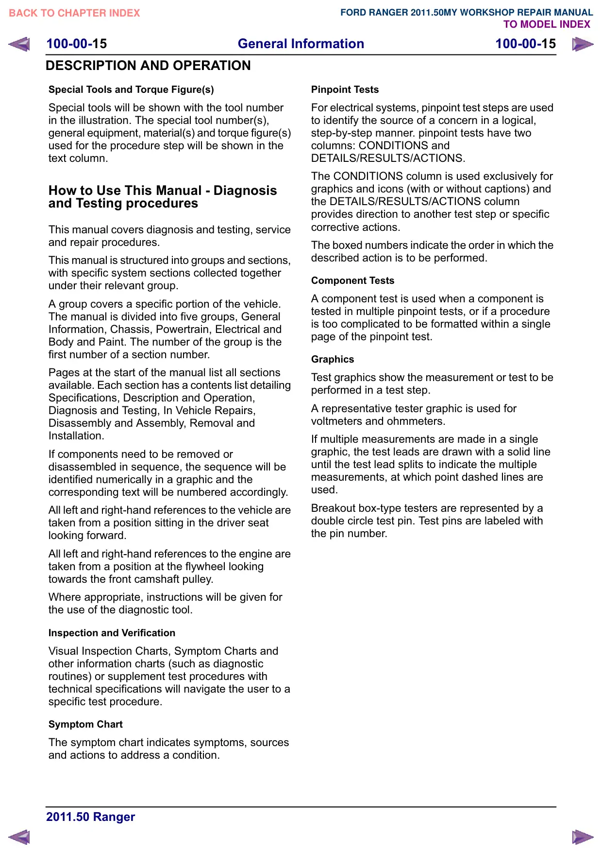
Texto da página
Link desta página: https://ranger.mbrace.com.br/oficina/20
Imagem: https://ranger.mbrace.com.br/img/oficina/20.webp
General Information
100-00-15
100-00-15
DESCRIPTION AND OPERATION
Special Tools and Torque Figure(s)
Special tools will be shown with the tool number
in the illustration. The special tool number(s),
general equipment, material(s) and torque figure(s)
used for the procedure step will be shown in the
text column.
How to Use This Manual - Diagnosis
and Testing procedures
This manual covers diagnosis and testing, service
and repair procedures.
This manual is structured into groups and sections,
with specific system sections collected together
under their relevant group.
A group covers a specific portion of the vehicle.
The manual is divided into five groups, General
Information, Chassis, Powertrain, Electrical and
Body and Paint. The number of the group is the
first number of a section number.
Pages at the start of the manual list all sections
available. Each section has a contents list detailing
Specifications, Description and Operation,
Diagnosis and Testing, In Vehicle Repairs,
Disassembly and Assembly, Removal and
Installation.
If components need to be removed or
disassembled in sequence, the sequence will be
identified numerically in a graphic and the
corresponding text will be numbered accordingly.
All left and right-hand references to the vehicle are
taken from a position sitting in the driver seat
looking forward.
All left and right-hand references to the engine are
taken from a position at the flywheel looking
towards the front camshaft pulley.
Where appropriate, instructions will be given for
the use of the diagnostic tool.
Inspection and Verification
Visual Inspection Charts, Symptom Charts and
other information charts (such as diagnostic
routines) or supplement test procedures with
technical specifications will navigate the user to a
specific test procedure.
Symptom Chart
The symptom chart indicates symptoms, sources
and actions to address a condition.
Pinpoint Tests
For electrical systems, pinpoint test steps are used
to identify the source of a concern in a logical,
step-by-step manner. pinpoint tests have two
columns: CONDITIONS and
DETAILS/RESULTS/ACTIONS.
The CONDITIONS column is used exclusively for
graphics and icons (with or without captions) and
the DETAILS/RESULTS/ACTIONS column
provides direction to another test step or specific
corrective actions.
The boxed numbers indicate the order in which the
described action is to be performed.
Component Tests
A component test is used when a component is
tested in multiple pinpoint tests, or if a procedure
is too complicated to be formatted within a single
page of the pinpoint test.
Graphics
Test graphics show the measurement or test to be
performed in a test step.
A representative tester graphic is used for
voltmeters and ohmmeters.
If multiple measurements are made in a single
graphic, the test leads are drawn with a solid line
until the test lead splits to indicate the multiple
measurements, at which point dashed lines are
used.
Breakout box-type testers are represented by a
double circle test pin. Test pins are labeled with
the pin number.