Body and Equipment Mounting Manual
Ford Ranger 2011.5
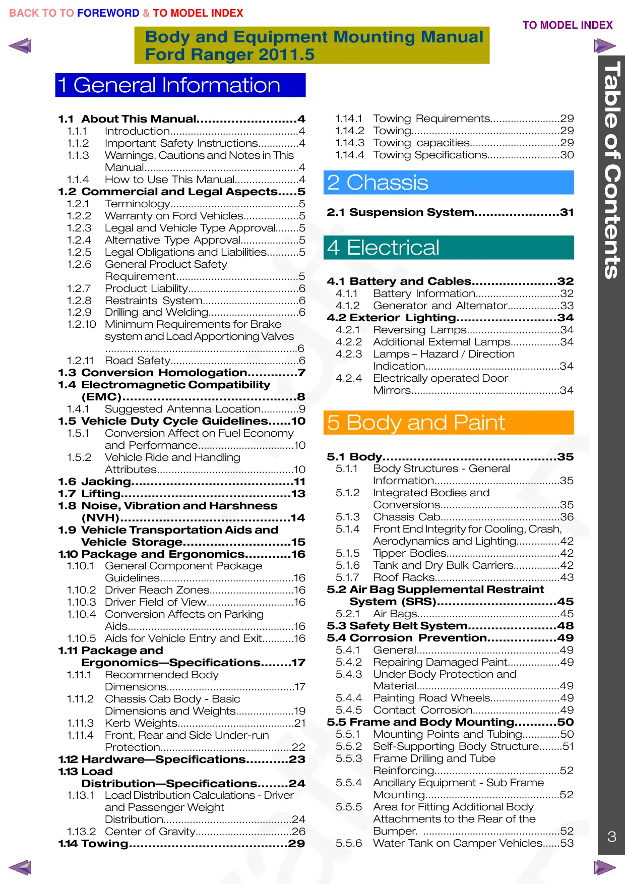
Table of Contents
1 General Information
1.1 About This Manual..........................4
1.1.1
Introduction............................................4
1.1.2
Important Safety Instructions..............4
1.1.3
Warnings, Cautions and Notes in This
Manual.....................................................4
1.1.4
How to Use This Manual......................4
1.2 Commercial and Legal Aspects.....5
1.2.1
Terminology............................................5
1.2.2
Warranty on Ford Vehicles...................5
1.2.3
Legal and Vehicle Type Approval........5
1.2.4
Alternative Type Approval....................5
1.2.5
Legal Obligations and Liabilities...........5
1.2.6
General Product Safety
Requirement..........................................5
1.2.7
Product Liability......................................6
1.2.8
Restraints System.................................6
1.2.9
Drilling and Welding...............................6
1.2.10
Minimum Requirements for Brake
system and Load Apportioning Valves
..................................................................6
1.2.11
Road Safety............................................6
1.3 Conversion Homologation.............7
1.4 Electromagnetic Compatibility
(EMC).............................................8
1.4.1
Suggested Antenna Location.............9
1.5 Vehicle Duty Cycle Guidelines......10
1.5.1
Conversion Affect on Fuel Economy
and Performance.................................10
1.5.2
Vehicle Ride and Handling
Attributes...............................................10
1.6 Jacking..........................................11
1.7 Lifting............................................13
1.8 Noise, Vibration and Harshness
(NVH)............................................14
1.9 Vehicle Transportation Aids and
Vehicle Storage............................15
1.10 Package and Ergonomics............16
1.10.1
General Component Package
Guidelines..............................................16
1.10.2
Driver Reach Zones.............................16
1.10.3
Driver Field of View..............................16
1.10.4
Conversion Affects on Parking
Aids.........................................................16
1.10.5
Aids for Vehicle Entry and Exit...........16
1.11 Package and
Ergonomics—Specifications........17
1.11.1
Recommended Body
Dimensions............................................17
1.11.2
Chassis Cab Body - Basic
Dimensions and Weights....................19
1.11.3
Kerb Weights........................................21
1.11.4
Front, Rear and Side Under-run
Protection.............................................22
1.12 Hardware—Specifications...........23
1.13 Load
Distribution—Specifications........24
1.13.1
Load Distribution Calculations - Driver
and Passenger Weight
Distribution............................................24
1.13.2
Center of Gravity.................................26
1.14 Towing.........................................29
1.14.1
Towing Requirements........................29
1.14.2
Towing...................................................29
1.14.3
Towing capacities...............................29
1.14.4
Towing Specifications.........................30
2 Chassis
2.1 Suspension System......................31
4 Electrical
4.1 Battery and Cables......................32
4.1.1
Battery Information.............................32
4.1.2
Generator and Alternator..................33
4.2 Exterior Lighting..........................34
4.2.1
Reversing Lamps................................34
4.2.2
Additional External Lamps.................34
4.2.3
Lamps – Hazard / Direction
Indication..............................................34
4.2.4
Electrically operated Door
Mirrors...................................................34
5 Body and Paint
5.1 Body.............................................35
5.1.1
Body Structures - General
Information...........................................35
5.1.2
Integrated Bodies and
Conversions.........................................35
5.1.3
Chassis Cab.........................................36
5.1.4
Front End Integrity for Cooling, Crash,
Aerodynamics and Lighting...............42
5.1.5
Tipper Bodies.......................................42
5.1.6
Tank and Dry Bulk Carriers................42
5.1.7
Roof Racks...........................................43
5.2 Air Bag Supplemental Restraint
System (SRS)...............................45
5.2.1
Air Bags.................................................45
5.3 Safety Belt System.......................48
5.4 Corrosion Prevention..................49
5.4.1
General.................................................49
5.4.2
Repairing Damaged Paint..................49
5.4.3
Under Body Protection and
Material.................................................49
5.4.4
Painting Road Wheels........................49
5.4.5
Contact Corrosion..............................49
5.5 Frame and Body Mounting...........50
5.5.1
Mounting Points and Tubing.............50
5.5.2
Self-Supporting Body Structure........51
5.5.3
Frame Drilling and Tube
Reinforcing...........................................52
5.5.4
Ancillary Equipment - Sub Frame
Mounting..............................................52
5.5.5
Area for Fitting Additional Body
Attachments to the Rear of the
Bumper. ...............................................52
3
5.5.6
Water Tank on Camper Vehicles......53
1 General Information
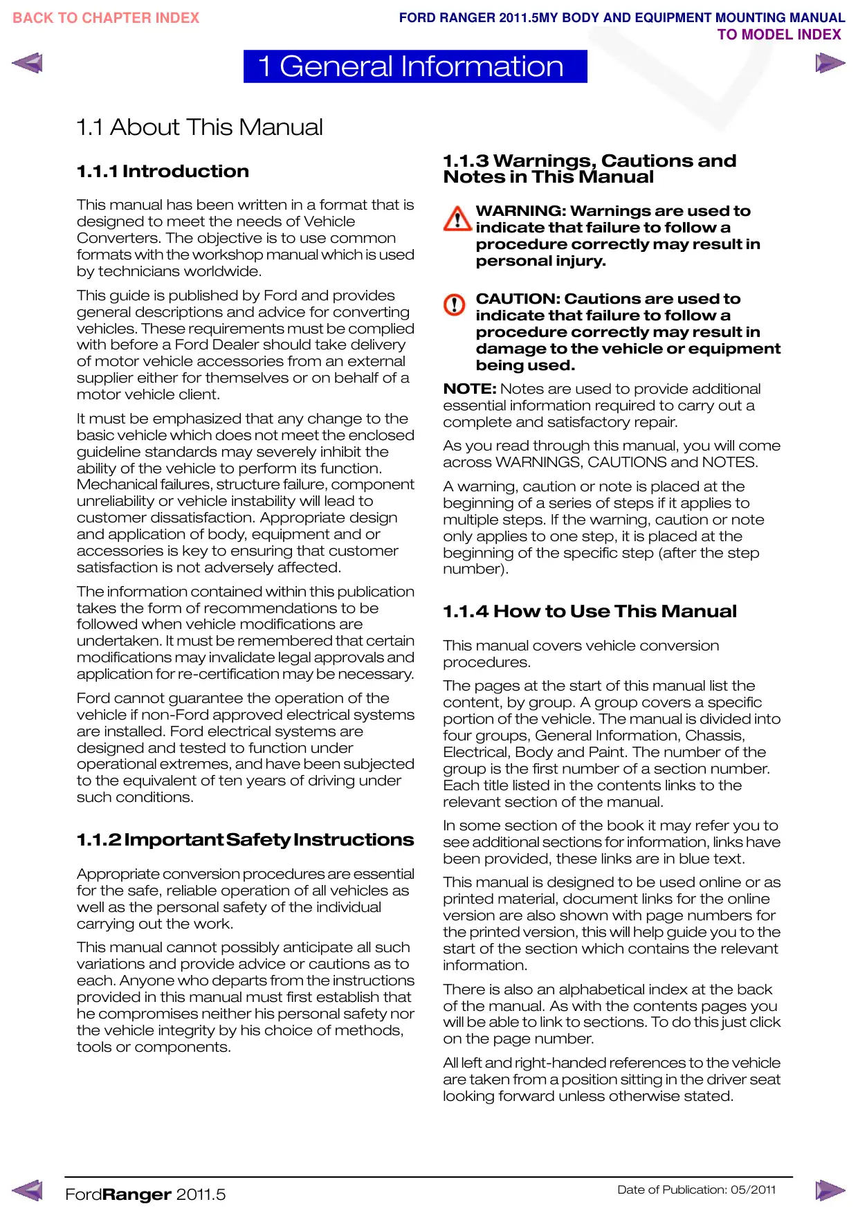
1.1 About This Manual
1.1.1 Introduction
This manual has been written in a format that is
designed to meet the needs of Vehicle
Converters. The objective is to use common
formats with the workshop manual which is used
by technicians worldwide.
This guide is published by Ford and provides
general descriptions and advice for converting
vehicles. These requirements must be complied
with before a Ford Dealer should take delivery
of motor vehicle accessories from an external
supplier either for themselves or on behalf of a
motor vehicle client.
It must be emphasized that any change to the
basic vehicle which does not meet the enclosed
guideline standards may severely inhibit the
ability of the vehicle to perform its function.
Mechanical failures, structure failure, component
unreliability or vehicle instability will lead to
customer dissatisfaction. Appropriate design
and application of body, equipment and or
accessories is key to ensuring that customer
satisfaction is not adversely affected.
The information contained within this publication
takes the form of recommendations to be
followed when vehicle modifications are
undertaken. It must be remembered that certain
modifications may invalidate legal approvals and
application for re-certification may be necessary.
Ford cannot guarantee the operation of the
vehicle if non-Ford approved electrical systems
are installed. Ford electrical systems are
designed and tested to function under
operational extremes, and have been subjected
to the equivalent of ten years of driving under
such conditions.
1.1.2ImportantSafetyInstructions
Appropriate conversion procedures are essential
for the safe, reliable operation of all vehicles as
well as the personal safety of the individual
carrying out the work.
This manual cannot possibly anticipate all such
variations and provide advice or cautions as to
each. Anyone who departs from the instructions
provided in this manual must first establish that
he compromises neither his personal safety nor
the vehicle integrity by his choice of methods,
tools or components.
FordRanger 2011.5
1.1.3 Warnings, Cautions and
Notes in This Manual
WARNING: Warnings are used to
indicate that failure to follow a
procedure correctly may result in
personal injury.
CAUTION: Cautions are used to
indicate that failure to follow a
procedure correctly may result in
damage to the vehicle or equipment
being used.
NOTE: Notes are used to provide additional
essential information required to carry out a
complete and satisfactory repair.
As you read through this manual, you will come
across WARNINGS, CAUTIONS and NOTES.
A warning, caution or note is placed at the
beginning of a series of steps if it applies to
multiple steps. If the warning, caution or note
only applies to one step, it is placed at the
beginning of the specific step (after the step
number).
1.1.4 How to Use This Manual
This manual covers vehicle conversion
procedures.
The pages at the start of this manual list the
content, by group. A group covers a specific
portion of the vehicle. The manual is divided into
four groups, General Information, Chassis,
Electrical, Body and Paint. The number of the
group is the first number of a section number.
Each title listed in the contents links to the
relevant section of the manual.
In some section of the book it may refer you to
see additional sections for information, links have
been provided, these links are in blue text.
This manual is designed to be used online or as
printed material, document links for the online
version are also shown with page numbers for
the printed version, this will help guide you to the
start of the section which contains the relevant
information.
There is also an alphabetical index at the back
of the manual. As with the contents pages you
will be able to link to sections. To do this just click
on the page number.
All left and right-handed references to the vehicle
are taken from a position sitting in the driver seat
looking forward unless otherwise stated.
Date of Publication: 05/2011
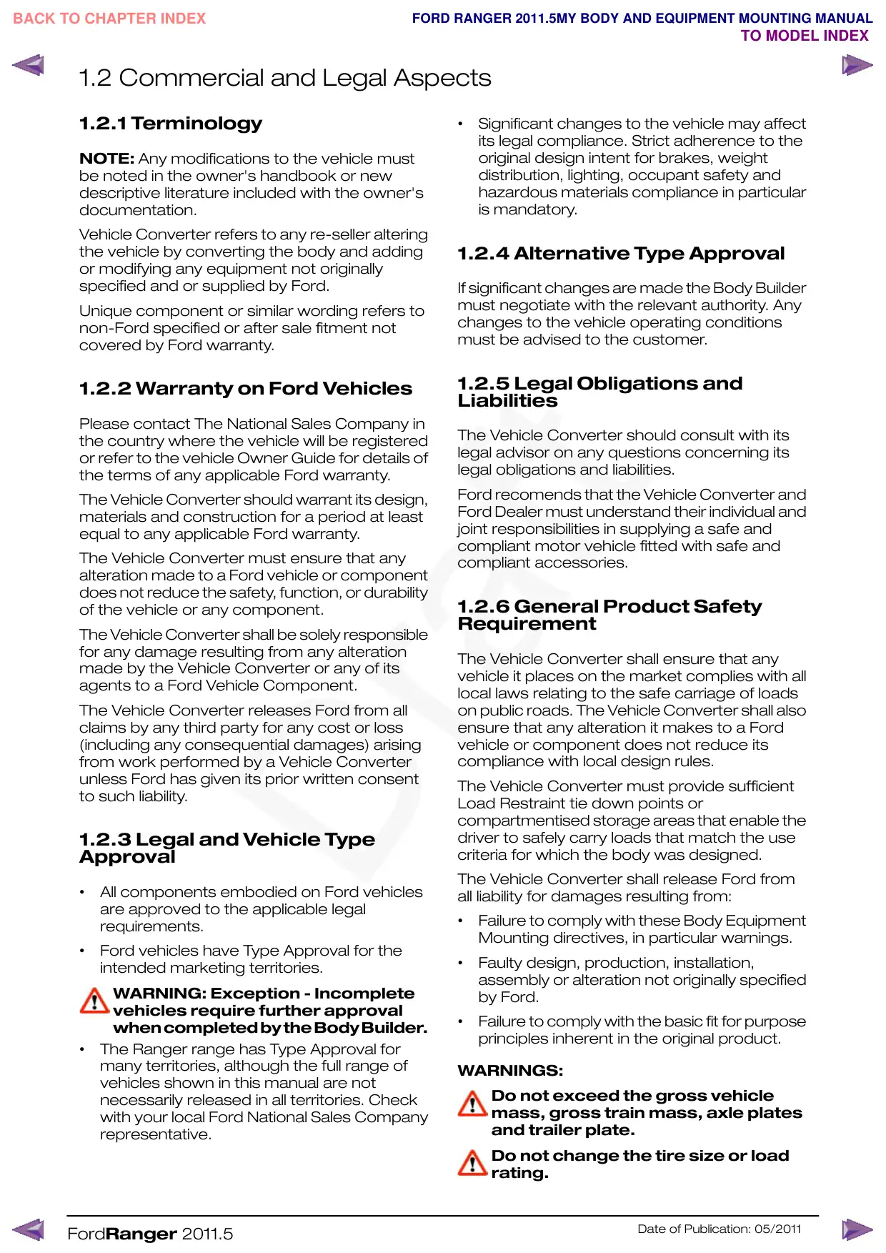
1.2 Commercial and Legal Aspects
1.2.1 Terminology
NOTE: Any modifications to the vehicle must
be noted in the owner's handbook or new
descriptive literature included with the owner's
documentation.
Vehicle Converter refers to any re-seller altering
the vehicle by converting the body and adding
or modifying any equipment not originally
specified and or supplied by Ford.
Unique component or similar wording refers to
non-Ford specified or after sale fitment not
covered by Ford warranty.
1.2.2 Warranty on Ford Vehicles
Please contact The National Sales Company in
the country where the vehicle will be registered
or refer to the vehicle Owner Guide for details of
the terms of any applicable Ford warranty.
The Vehicle Converter should warrant its design,
materials and construction for a period at least
equal to any applicable Ford warranty.
The Vehicle Converter must ensure that any
alteration made to a Ford vehicle or component
does not reduce the safety, function, or durability
of the vehicle or any component.
The Vehicle Converter shall be solely responsible
for any damage resulting from any alteration
made by the Vehicle Converter or any of its
agents to a Ford Vehicle Component.
The Vehicle Converter releases Ford from all
claims by any third party for any cost or loss
(including any consequential damages) arising
from work performed by a Vehicle Converter
unless Ford has given its prior written consent
to such liability.
1.2.3 Legal and Vehicle Type
Approval
•
All components embodied on Ford vehicles
are approved to the applicable legal
requirements.
•
Ford vehicles have Type Approval for the
intended marketing territories.
WARNING: Exception - Incomplete
vehicles require further approval
whencompletedbytheBodyBuilder.
•
The Ranger range has Type Approval for
many territories, although the full range of
vehicles shown in this manual are not
necessarily released in all territories. Check
with your local Ford National Sales Company
representative.
FordRanger 2011.5
•
Significant changes to the vehicle may affect
its legal compliance. Strict adherence to the
original design intent for brakes, weight
distribution, lighting, occupant safety and
hazardous materials compliance in particular
is mandatory.
1.2.4 Alternative Type Approval
If significant changes are made the Body Builder
must negotiate with the relevant authority. Any
changes to the vehicle operating conditions
must be advised to the customer.
1.2.5 Legal Obligations and
Liabilities
The Vehicle Converter should consult with its
legal advisor on any questions concerning its
legal obligations and liabilities.
Ford recomends that the Vehicle Converter and
Ford Dealer must understand their individual and
joint responsibilities in supplying a safe and
compliant motor vehicle fitted with safe and
compliant accessories.
1.2.6 General Product Safety
Requirement
The Vehicle Converter shall ensure that any
vehicle it places on the market complies with all
local laws relating to the safe carriage of loads
on public roads. The Vehicle Converter shall also
ensure that any alteration it makes to a Ford
vehicle or component does not reduce its
compliance with local design rules.
The Vehicle Converter must provide sufficient
Load Restraint tie down points or
compartmentised storage areas that enable the
driver to safely carry loads that match the use
criteria for which the body was designed.
The Vehicle Converter shall release Ford from
all liability for damages resulting from:
•
Failure to comply with these Body Equipment
Mounting directives, in particular warnings.
•
Faulty design, production, installation,
assembly or alteration not originally specified
by Ford.
•
Failure to comply with the basic fit for purpose
principles inherent in the original product.
WARNINGS:
Do not exceed the gross vehicle
mass, gross train mass, axle plates
and trailer plate.
Do not change the tire size or load
rating.
Date of Publication: 05/2011
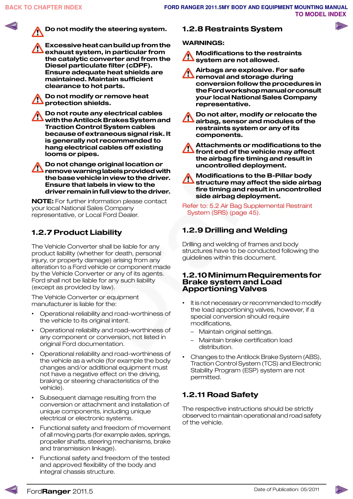
1.2.8 Restraints System
Do not modify the steering system.
WARNINGS:
Excessive heat can build up from the
exhaust system, in particular from
the catalytic converter and from the
Diesel particulate filter (cDPF).
Ensure adequate heat shields are
maintained. Maintain sufficient
clearance to hot parts.
Do not modify or remove heat
protection shields.
Do not route any electrical cables
withtheAntilockBrakesSystemand
Traction Control System cables
because of extraneous signal risk. It
is generally not recommended to
hang electrical cables off existing
looms or pipes.
Do not change original location or
removewarninglabelsprovidedwith
the base vehicle in view to the driver.
Ensure that labels in view to the
driver remain in full view to the driver.
NOTE: For further information please contact
your local National Sales Company
representative, or Local Ford Dealer.
1.2.7 Product Liability
The Vehicle Converter shall be liable for any
product liability (whether for death, personal
injury, or property damage) arising from any
alteration to a Ford vehicle or component made
by the Vehicle Converter or any of its agents.
Ford shall not be liable for any such liability
(except as provided by law).
The Vehicle Converter or equipment
manufacturer is liable for the:
•
Operational reliability and road-worthiness of
the vehicle to its original intent.
•
Operational reliability and road-worthiness of
any component or conversion, not listed in
original Ford documentation.
•
Operational reliability and road-worthiness of
the vehicle as a whole (for example the body
changes and/or additional equipment must
not have a negative effect on the driving,
braking or steering characteristics of the
vehicle).
•
Subsequent damage resulting from the
conversion or attachment and installation of
unique components, including unique
electrical or electronic systems.
•
Functional safety and freedom of movement
of all moving parts (for example axles, springs,
propeller shafts, steering mechanisms, brake
and transmission linkage).
•
Functional safety and freedom of the tested
and approved flexibility of the body and
integral chassis structure.
FordRanger 2011.5
Modifications to the restraints
system are not allowed.
Airbags are explosive. For safe
removal and storage during
conversion follow the procedures in
theFordworkshopmanualorconsult
your local National Sales Company
representative.
Do not alter, modify or relocate the
airbag, sensor and modules of the
restraints system or any of its
components.
Attachments or modifications to the
front end of the vehicle may affect
the airbag fire timing and result in
uncontrolled deployment.
Modifications to the B-Pillar body
structure may affect the side airbag
fire timing and result in uncontrolled
side airbag deployment.
Refer to: 5.2 Air Bag Supplemental Restraint
System (SRS) (page 45).
1.2.9 Drilling and Welding
Drilling and welding of frames and body
structures have to be conducted following the
guidelines within this document.
1.2.10MinimumRequirementsfor
Brake system and Load
Apportioning Valves
•
It is not necessary or recommended to modify
the load apportioning valves, however, if a
special conversion should require
modifications,
–
Maintain original settings.
–
Maintain brake certification load
distribution.
•
Changes to the Antilock Brake System (ABS),
Traction Control System (TCS) and Electronic
Stability Program (ESP) system are not
permitted.
1.2.11 Road Safety
The respective instructions should be strictly
observed to maintain operational and road safety
of the vehicle.
Date of Publication: 05/2011
1.3 Conversion Homologation
The Vehicle Converter must observe any
statutory rules and regulations. When the
conversion needs a new approval the following
information must be quoted.
•
All dimensional, weight and centre of gravity
data.
•
The fixing of the body to the donor vehicle.
•
Operating conditions.
The responsible Technical Service may require
additional information and/or testing.
NOTE: For further information please contact
your local National Sales Company
representative, or Local Ford Dealer.
FordRanger 2011.5
Date of Publication: 05/2011
1.4 Electromagnetic Compatibility (EMC)
WARNINGS:
Your vehicle has been tested and
certified to European legislation
relating to electromagnetic
compatibility (2004/104/EC). It is
yourresponsibilitytoensurethatany
equipment fitted complies with
applicable local legislation. Ensure
you have any equipment fitted by
properly trained technicians.
Radio frequency (RF) transmitter
equipment (for example: cellular
telephones, amateur radio
transmitters and so on.) may only be
fitted to your vehicle if they comply
with the parameters shown in the
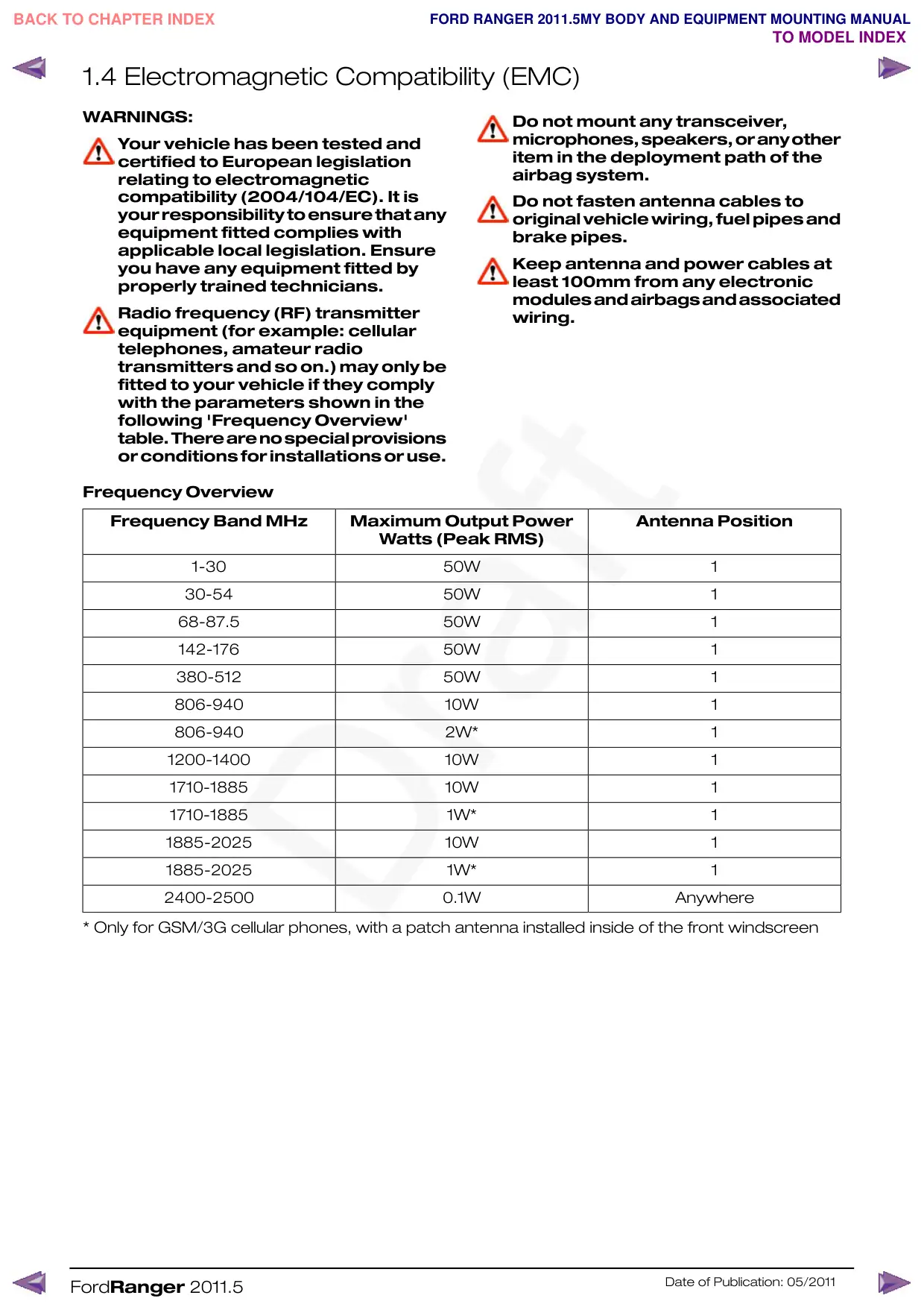
following 'Frequency Overview'
table.Therearenospecialprovisions
or conditions for installations or use.
Frequency Overview
Frequency Band MHz
Maximum Output Power
Watts (Peak RMS)
1-30
30-54
68-87.5
142-176
380-512
806-940
806-940
1200-1400
1710-1885
1710-1885
1885-2025
1885-2025
2400-2500
* Only for GSM/3G cellular phones, with a patch antenna installed inside of the front windscreen
FordRanger 2011.5
Do not mount any transceiver,
microphones,speakers,oranyother
item in the deployment path of the
airbag system.
Do not fasten antenna cables to
original vehicle wiring, fuel pipes and
brake pipes.
Keep antenna and power cables at
least 100mm from any electronic
modulesandairbagsandassociated
wiring.
Antenna Position
50W
1
50W
1
50W
1
50W
1
50W
1
10W
1
2W*
1
10W
1
10W
1
1W*
1
10W
1
1W*
1
0.1W
Anywhere
Date of Publication: 05/2011
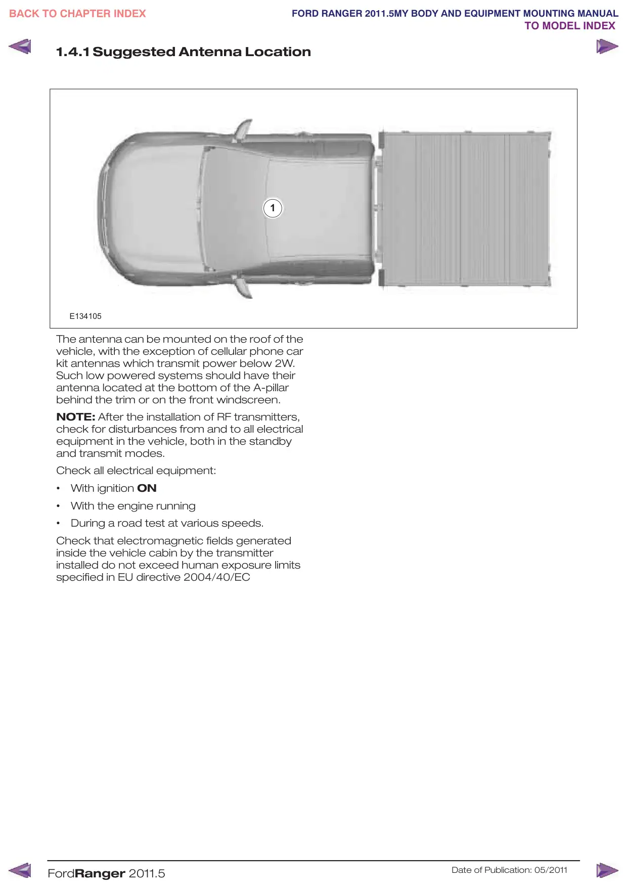
1.4.1 Suggested Antenna Location
1
E134105
The antenna can be mounted on the roof of the
vehicle, with the exception of cellular phone car
kit antennas which transmit power below 2W.
Such low powered systems should have their
antenna located at the bottom of the A-pillar
behind the trim or on the front windscreen.
NOTE: After the installation of RF transmitters,
check for disturbances from and to all electrical
equipment in the vehicle, both in the standby
and transmit modes.
Check all electrical equipment:
•
With ignition ON
•
With the engine running
•
During a road test at various speeds.
Check that electromagnetic fields generated
inside the vehicle cabin by the transmitter
installed do not exceed human exposure limits
specified in EU directive 2004/40/EC
FordRanger 2011.5
Date of Publication: 05/2011
1.5 Vehicle Duty Cycle Guidelines
It is necessary to take into account the customer
usage profile and the anticipated vehicle duty
cycles of the modified vehicle in order to choose
the appropriate specification of the base vehicle.
It is necessary to select the appropriate drive,
engine, gear ratio, gross vehicle mass, gross
train mass, axle plates and payloads of the base
vehicle to match the customer requirements.
Where possible make sure that the base vehicle
is ordered with any necessary plant fit options.
NOTE: For further information please contact
your local National Sales Company
representative, or Local Ford Dealer.
1.5.1 Conversion Affect on Fuel
Economy and Performance
Any conversion may effect the fuel consumption
and performance depending on the
aerodynamics and the weight added by the
conversion. The published information for fuel
consumption and performance of the base
vehicle therefore may not be valid. It is advisable
to control the weight, but without deteriorating
other vehicle attributes and functions (especially
those related to safety and durability).
1.5.2 Vehicle Ride and Handling
Attributes
CAUTION: Do not exceed the axle
plate, gross vehicle mass, trailer
plate and gross trailer mass limits.
Due to the displacement of the center of gravity
occurred by the conversion the ride and handling
attributes may be different to the base vehicle.
NOTE: This vehicle should be evaluated for safe
operation prior to sale.
FordRanger 2011.5
Date of Publication: 05/2011
1.6 Jacking
WARNINGS:
Alwayspositionthevehicleonahard
level surface. If the vehicle must be
jacked up on a soft surface use load
spreading blocks under the jack.
Always chock the wheel diagonally
opposite the jacking point. Failure to
follow these instructions may result
in personal injury.
Do not get under a vehicle that is
supported by a jack.
This jack is only intended for
changing wheels.
CAUTIONS:
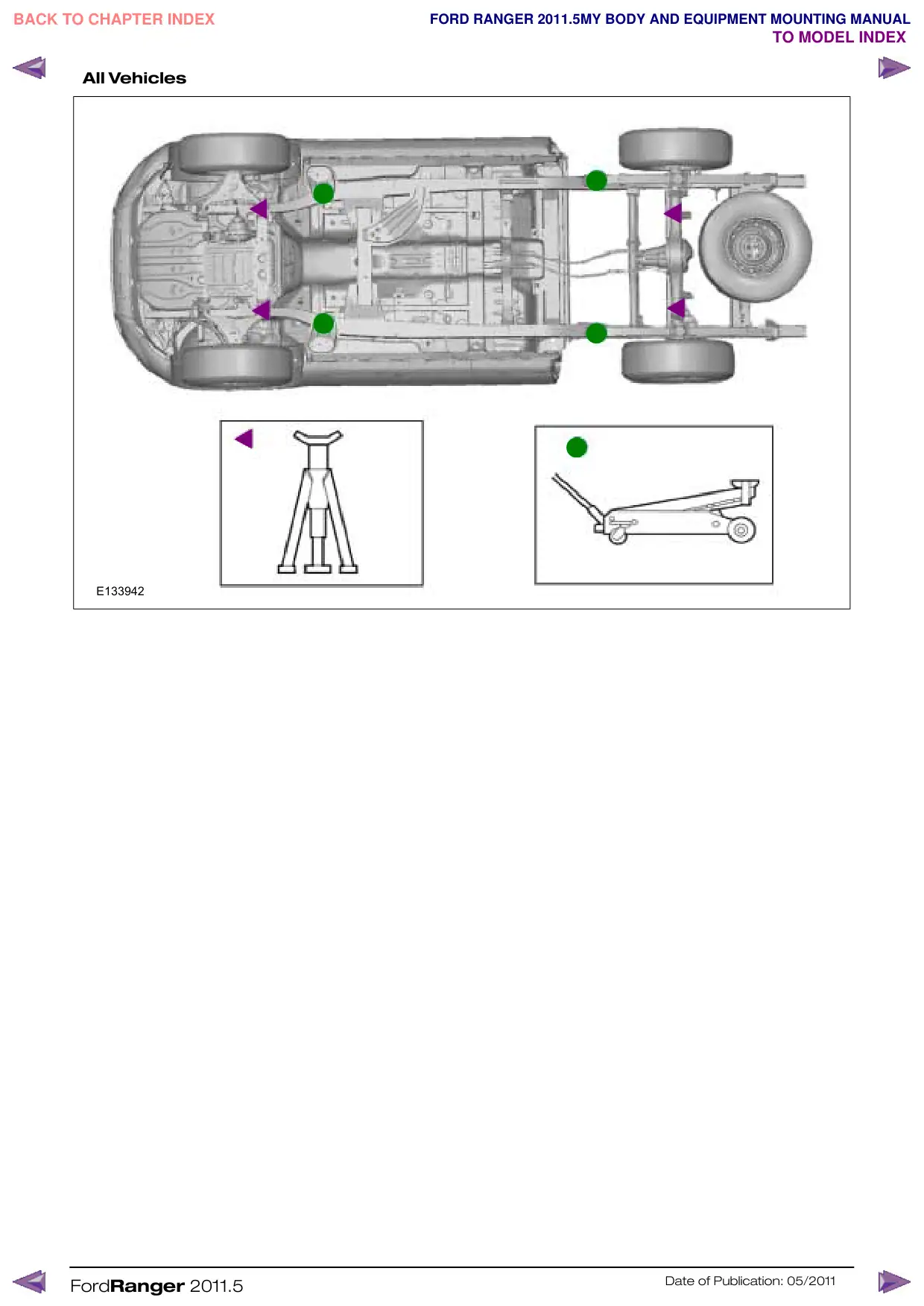
It is important that only the correct
jacking and support locations are
used at all times.
Make sure that access to the spare
wheelismaintainedwhenconverting
the vehicle or relocating the spare
wheel.
NOTE: When using the vehicle jack, refer to the
owner guide for correct operating instructions.
NOTE: Make sure that reinforcements are
installed to maintain the integrity of the original
body structure for/at jacking points.
NOTE: Any modifications to the vehicle must
be noted in the owner's handbook or new
descriptive literature included with the owner's
documentation.
FordRanger 2011.5
The spare wheel winch is located above the
spare wheel and can be accessed from the rear
of the chassis frame.
The jack must be assembled and fixed
appropriately to the body to ensure safety,
durability and accessibility.
E140512
1. Ensure screwthread is adequately lubricated
before use.
2. The jack should be used on level firm ground
wherever possible.
3. Apply park brake fully before lifting the vehicle.
4. It is recommended that the wheels of the
vehicle should be chocked, and no person
should remain in a vehicle being jacked.
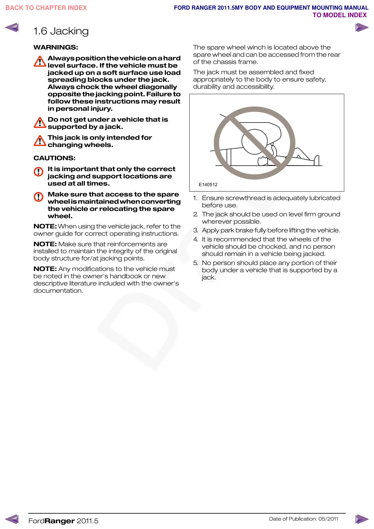
5. No person should place any portion of their
body under a vehicle that is supported by a
jack.
Date of Publication: 05/2011
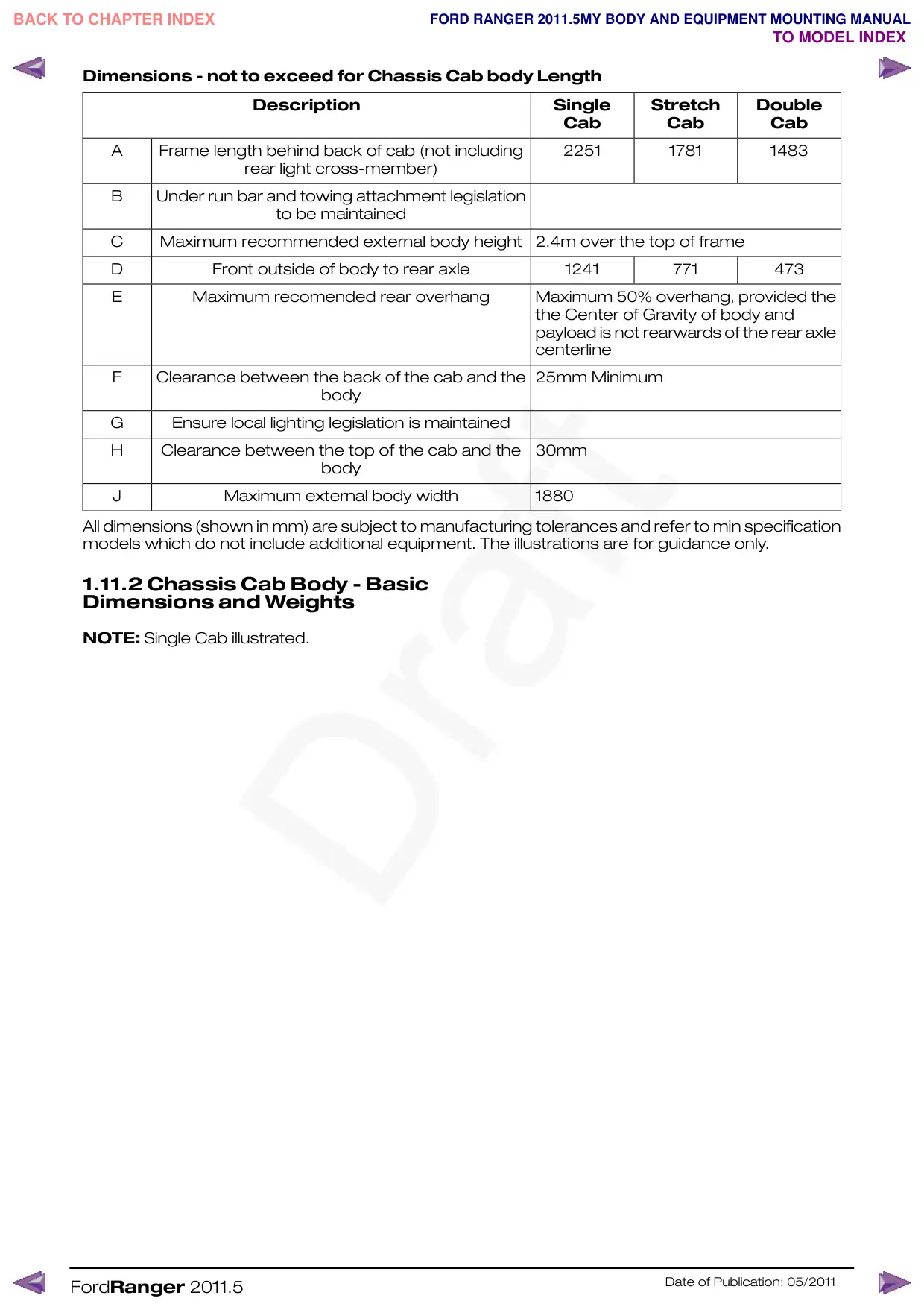
Dimensions - not to exceed for Chassis Cab body Length
Description
Single
Stretch
Double
A
Frame length behind back of cab (not including
rear light cross-member)
B
Under run bar and towing attachment legislation
to be maintained
C
Maximum recommended external body height
D
Front outside of body to rear axle
E
Maximum recomended rear overhang
F
Clearance between the back of the cab and the
body
G
Ensure local lighting legislation is maintained
H
Clearance between the top of the cab and the
body
J
Maximum external body width
All dimensions (shown in mm) are subject to manufacturing tolerances and refer to min specification
models which do not include additional equipment. The illustrations are for guidance only.
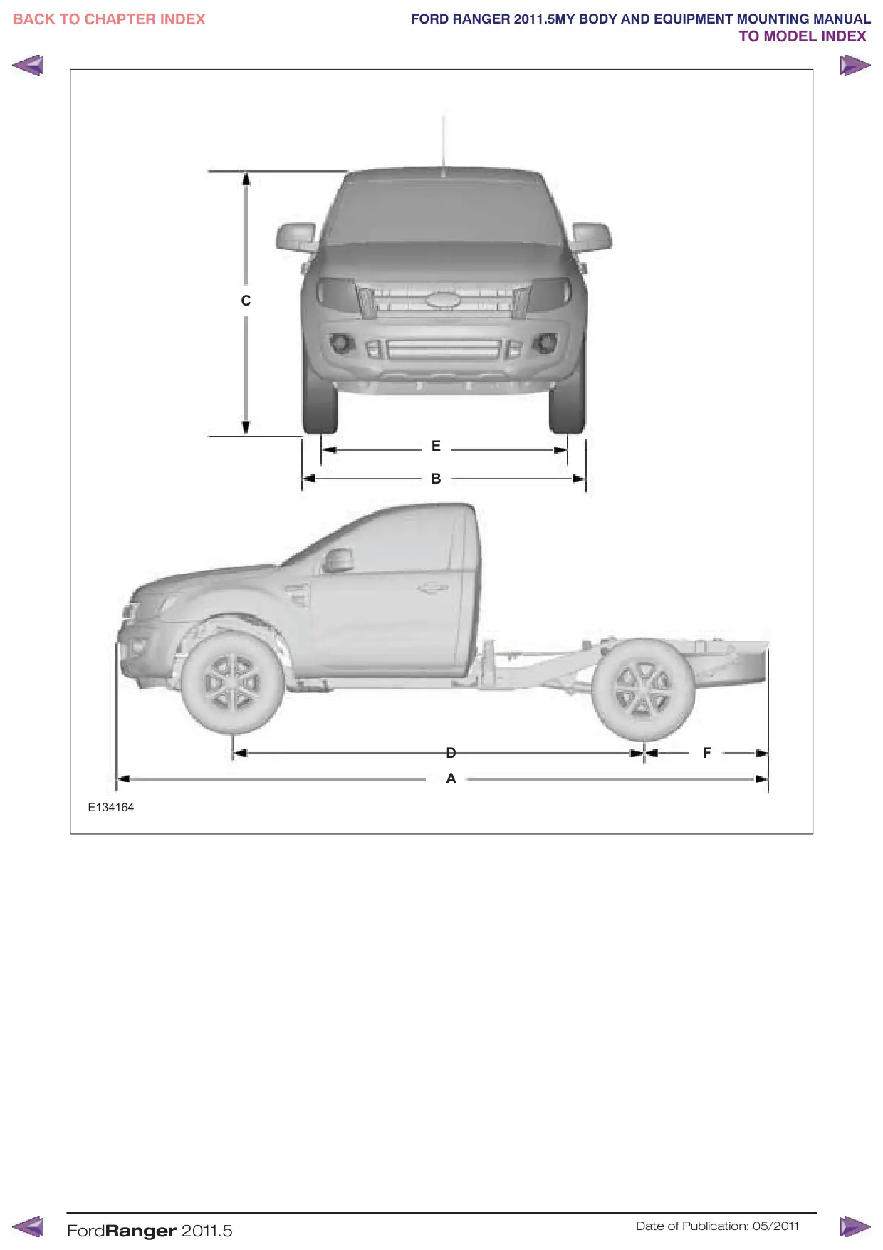
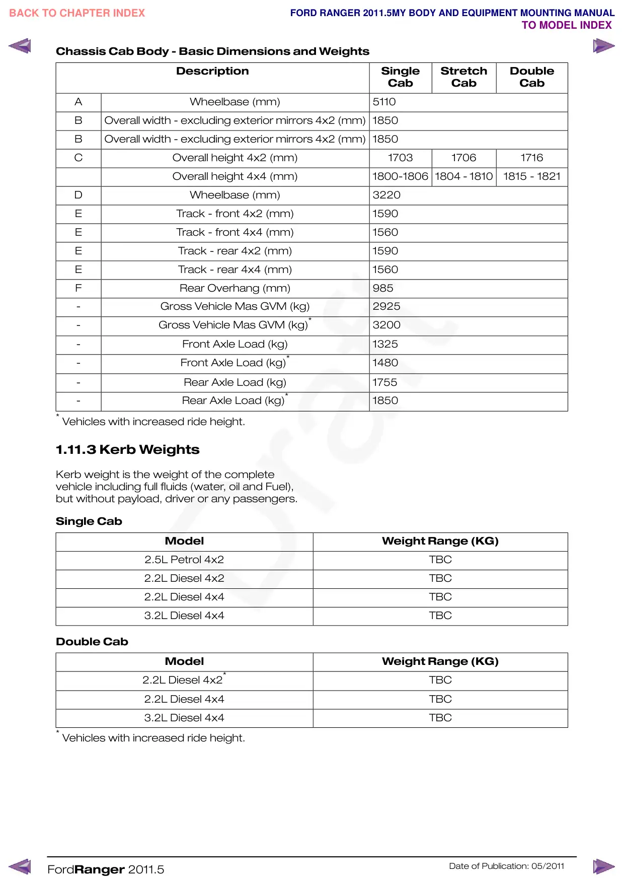
1.11.2 Chassis Cab Body - Basic
Dimensions and Weights
NOTE: Single Cab illustrated.
FordRanger 2011.5
Cab
Cab
Cab
2251
1781
1483
2.4m over the top of frame
1241
771
473
Maximum 50% overhang, provided the
the Center of Gravity of body and
payload is not rearwards of the rear axle
centerline
25mm Minimum
30mm
1880
Date of Publication: 05/2011
Stretch Cab
Model
Weight Range (KG)
2.2L Diesel 4x2*
3.2L Diesel 4x2*
2.2L Diesel 4x4
3.2L Diesel 4x4
* Vehicles with increased ride height.
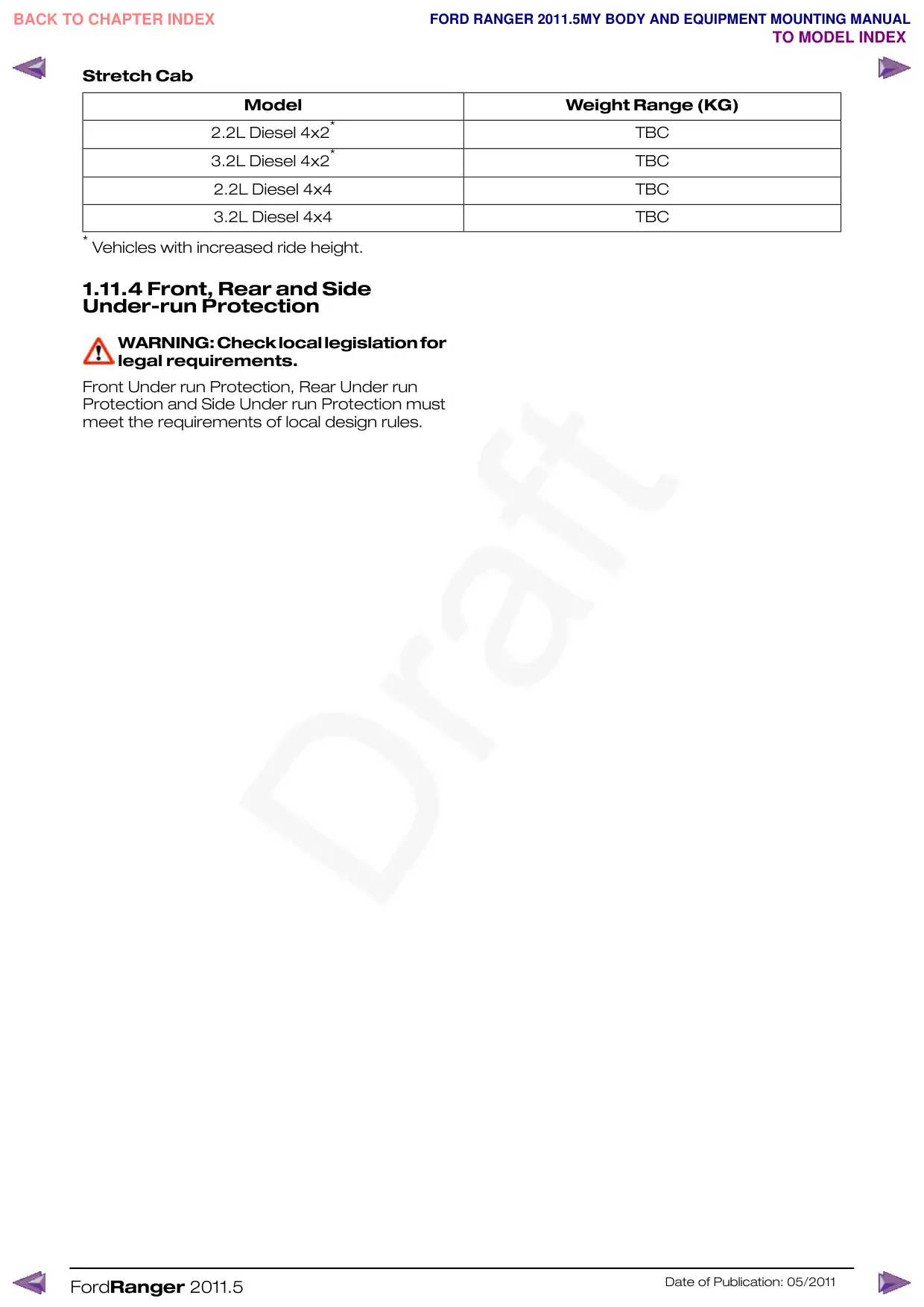
1.11.4 Front, Rear and Side
Under-run Protection
WARNING:Checklocallegislationfor
legal requirements.
Front Under run Protection, Rear Under run
Protection and Side Under run Protection must
meet the requirements of local design rules.
FordRanger 2011.5
TBC
TBC
TBC
TBC
Date of Publication: 05/2011
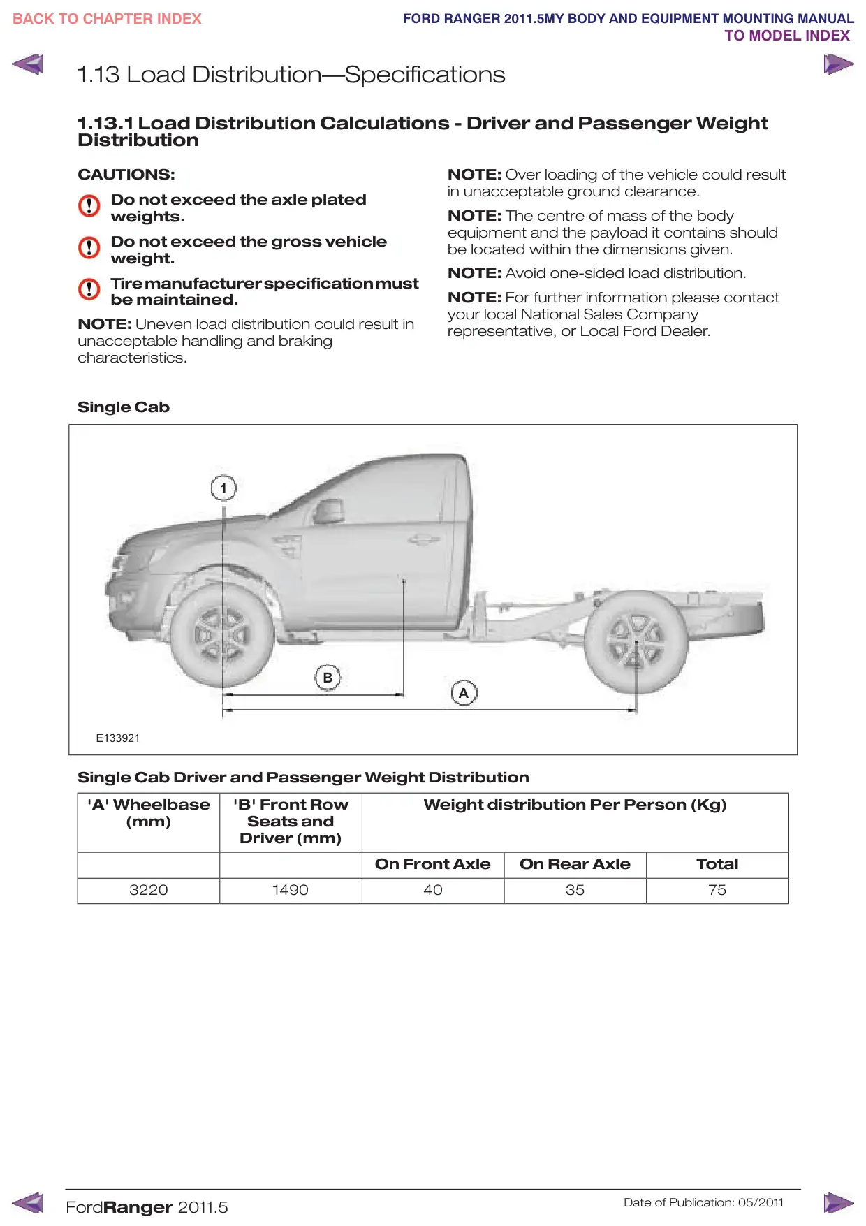
1.13 Load Distribution—Specifications
1.13.1 Load Distribution Calculations - Driver and Passenger Weight
Distribution
CAUTIONS:
Do not exceed the axle plated
weights.
Do not exceed the gross vehicle
weight.
Tiremanufacturerspecificationmust
be maintained.
NOTE: Uneven load distribution could result in
unacceptable handling and braking
characteristics.
Single Cab
1
B
E133921
Single Cab Driver and Passenger Weight Distribution
'A' Wheelbase
'B' Front Row
(mm)
Seats and
Driver (mm)
On Front Axle
3220
1490
FordRanger 2011.5
NOTE: Over loading of the vehicle could result
in unacceptable ground clearance.
NOTE: The centre of mass of the body
equipment and the payload it contains should
be located within the dimensions given.
NOTE: Avoid one-sided load distribution.
NOTE: For further information please contact
your local National Sales Company
representative, or Local Ford Dealer.
A
Weight distribution Per Person (Kg)
On Rear Axle
Total
40
35
75
Date of Publication: 05/2011
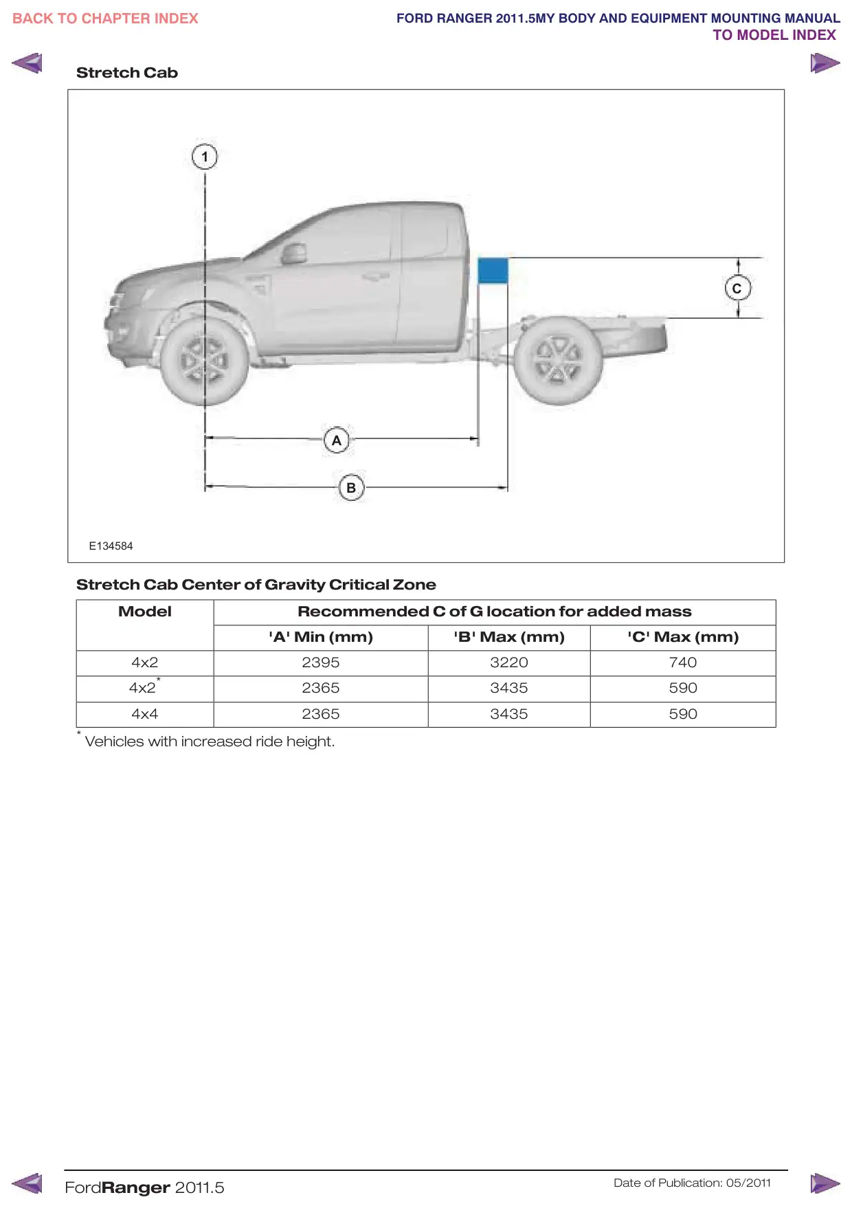
Stretch Cab
1
A
B
E134584
Stretch Cab Center of Gravity Critical Zone
Model
Recommended C of G location for added mass
'A' Min (mm)
4x2
2395
4x2*
2365
4x4
2365
* Vehicles with increased ride height.
FordRanger 2011.5
C
'B' Max (mm)
'C' Max (mm)
3220
740
3435
590
3435
590
Date of Publication: 05/2011
1.14 Towing
1.14.1 Towing Requirements
When a towing device is required, the Vehicle
Converter should use a Ford approved tow bar.
Refer to: 1.13 (page 24).
Load Distribution
Refer to: 1.6 Jacking (page 11).
1.14.2 Towing
For towing devices fitted by the Vehicle
Converter the following applies:
•
Towing allowances must not exceed those
of the standard vehicle.
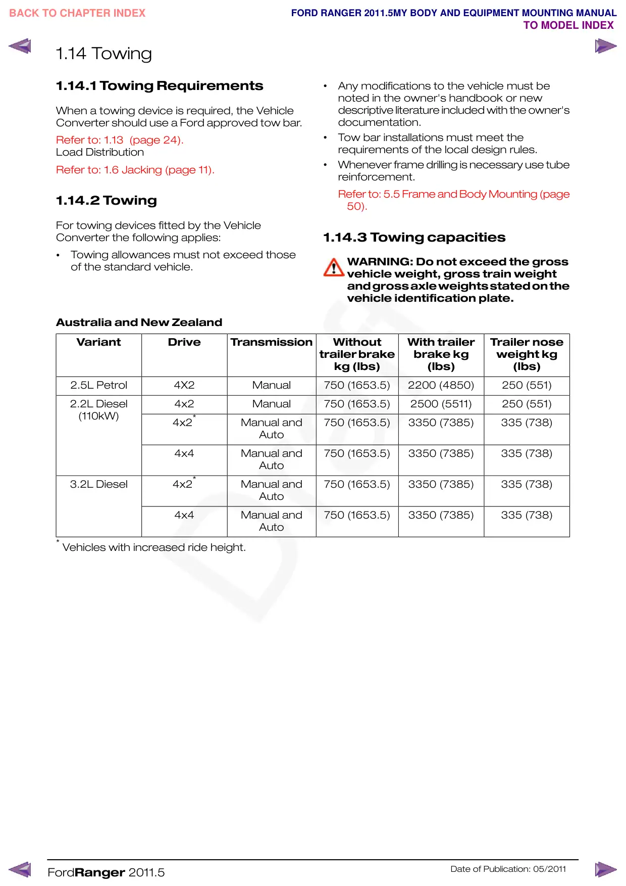
Australia and New Zealand
Variant
Drive
Transmission
2.5L Petrol
4X2
Manual
2.2L Diesel
4x2
Manual
(110kW)
4x2*
Manual and
Auto
4x4
Manual and
Auto
4x2*
3.2L Diesel
Manual and
Auto
4x4
Manual and
Auto
* Vehicles with increased ride height.
FordRanger 2011.5
•
Any modifications to the vehicle must be
noted in the owner's handbook or new
descriptive literature included with the owner's
documentation.
•
Tow bar installations must meet the
requirements of the local design rules.
•
Whenever frame drilling is necessary use tube
reinforcement.
Refer to: 5.5 Frame and Body Mounting (page
50).
1.14.3 Towing capacities
WARNING: Do not exceed the gross
vehicle weight, gross train weight
andgrossaxleweightsstatedonthe
vehicle identification plate.
Without
With trailer
Trailer nose
trailer brake
brake kg
weight kg
kg (lbs)
(lbs)
(lbs)
750 (1653.5)
2200 (4850)
250 (551)
750 (1653.5)
2500 (5511)
250 (551)
750 (1653.5)
3350 (7385)
335 (738)
750 (1653.5)
3350 (7385)
335 (738)
750 (1653.5)
3350 (7385)
335 (738)
750 (1653.5)
3350 (7385)
335 (738)
Date of Publication: 05/2011
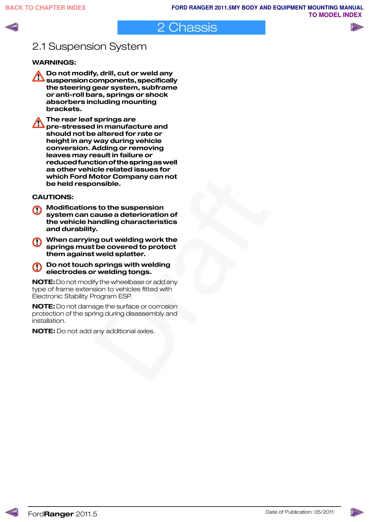
2 Chassis
2.1 Suspension System
WARNINGS:
Do not modify, drill, cut or weld any
suspensioncomponents,specifically
the steering gear system, subframe
or anti-roll bars, springs or shock
absorbers including mounting
brackets.
The rear leaf springs are
pre-stressed in manufacture and
should not be altered for rate or
height in any way during vehicle
conversion. Adding or removing
leaves may result in failure or
reducedfunctionofthespringaswell
as other vehicle related issues for
which Ford Motor Company can not
be held responsible.
CAUTIONS:
Modifications to the suspension
system can cause a deterioration of
the vehicle handling characteristics
and durability.
When carrying out welding work the
springs must be covered to protect
them against weld splatter.
Do not touch springs with welding
electrodes or welding tongs.
NOTE: Do not modify the wheelbase or add any
type of frame extension to vehicles fitted with
Electronic Stability Program ESP.
NOTE: Do not damage the surface or corrosion
protection of the spring during disassembly and
installation.
NOTE: Do not add any additional axles.
FordRanger 2011.5
Date of Publication: 05/2011