501-20B-1
Supplemental Restraint System
501-20B-1
.
SECTION 501-20B Supplemental Restraint System
VEHICLE APPLICATION: 2011.50 Ranger
CONTENTS
DESCRIPTION AND OPERATION
Air Bag and Safety Belt Pretensioner Supplemental Restraint System (SRS) (Component
Location)...........................................................................................................................
Air Bag and Safety Belt Pretensioner Supplemental Restraint System (SRS)...................
System overview................................................................................................................
RCM (Restraint Control Module)........................................................................................
Passenger air bag deactivation switch...............................................................................
Air bag warning indicator....................................................................................................
Driver air bag and driver lower air bag...............................................................................
Side impact sensors...........................................................................................................
Side air curtain....................................................................................................................
Front impact severity sensor..............................................................................................
Safety belt retractor and pretensioners..............................................................................
Side air bag........................................................................................................................
Passenger air bag..............................................................................................................
GENERAL PROCEDURES
Clockspring Adjustment......................................................................................................
Deployed Air Bag Disposal.................................................................................................
Scrapped Vehicle Air Bag and Safety Belt Pretensioner Disposal - In-Vehicle Disposal....
Unserviceable Air Bag Disposal.........................................................................................
Unserviceable Air Bag Disposal.........................................................................................
REMOVAL AND INSTALLATION
Driver Air Bag Module.........................................................................................................
Passenger Air Bag Module.................................................................................................
Driver Lower Air Bag Module..............................................................................................
Side Air Bag Module...........................................................................................................
Side Air Curtain Module......................................................................................................
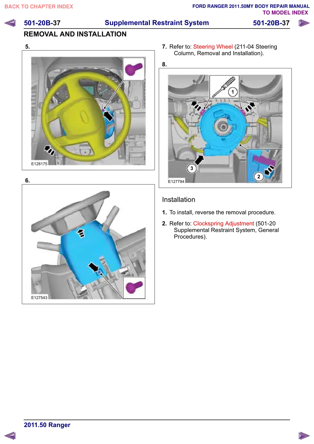
Clockspring.........................................................................................................................
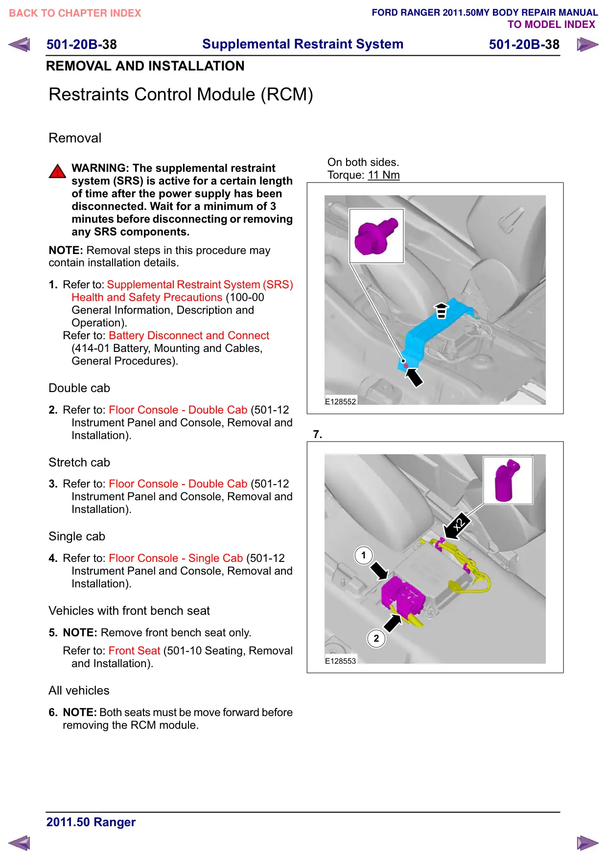
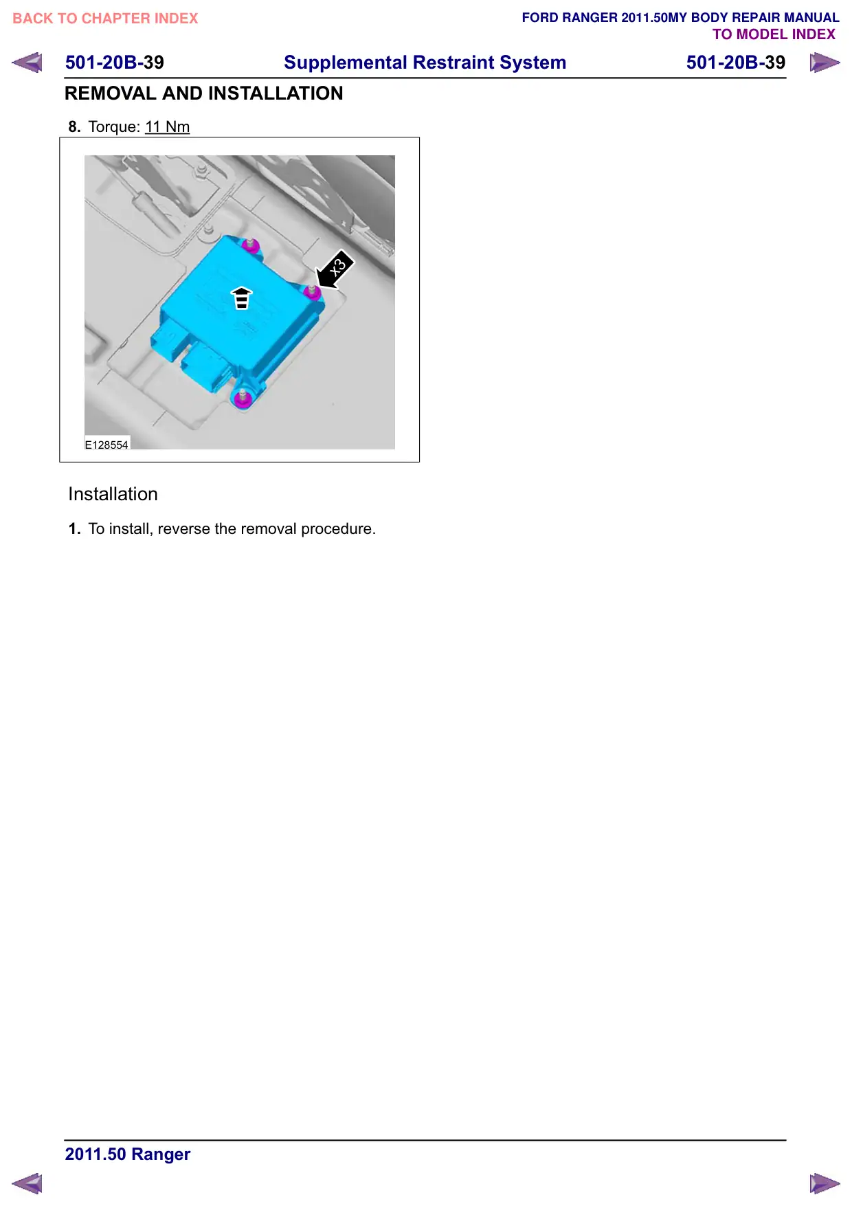
Restraints Control Module (RCM)......................................................................................
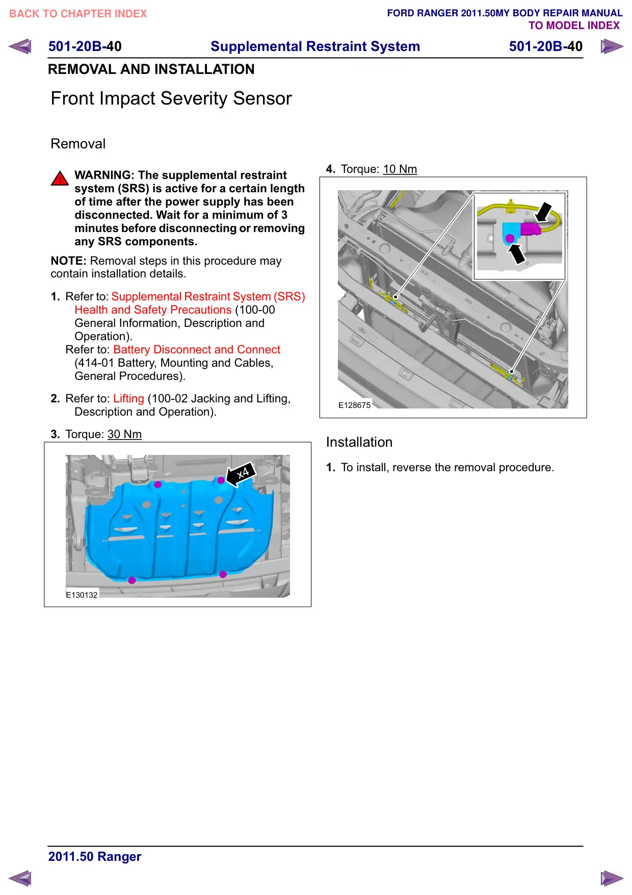
Front Impact Severity Sensor.............................................................................................
Side Impact Sensor............................................................................................................
PAGE
501-20B-2
501-20B-7
501-20B-7
501-20B-9
501-20B-9
501-20B-9
501-20B-10
501-20B-10
501-20B-10
501-20B-11
501-20B-11
501-20B-11
501-20B-11
501-20B-12
501-20B-13
501-20B-14
501-20B-24
501-20B-25
501-20B-26
501-20B-28
501-20B-29
501-20B-31
501-20B-33
501-20B-36
501-20B-38
501-20B-40
501-20B-41
501-20B-2
Supplemental Restraint System
501-20B-2
DESCRIPTION AND OPERATION
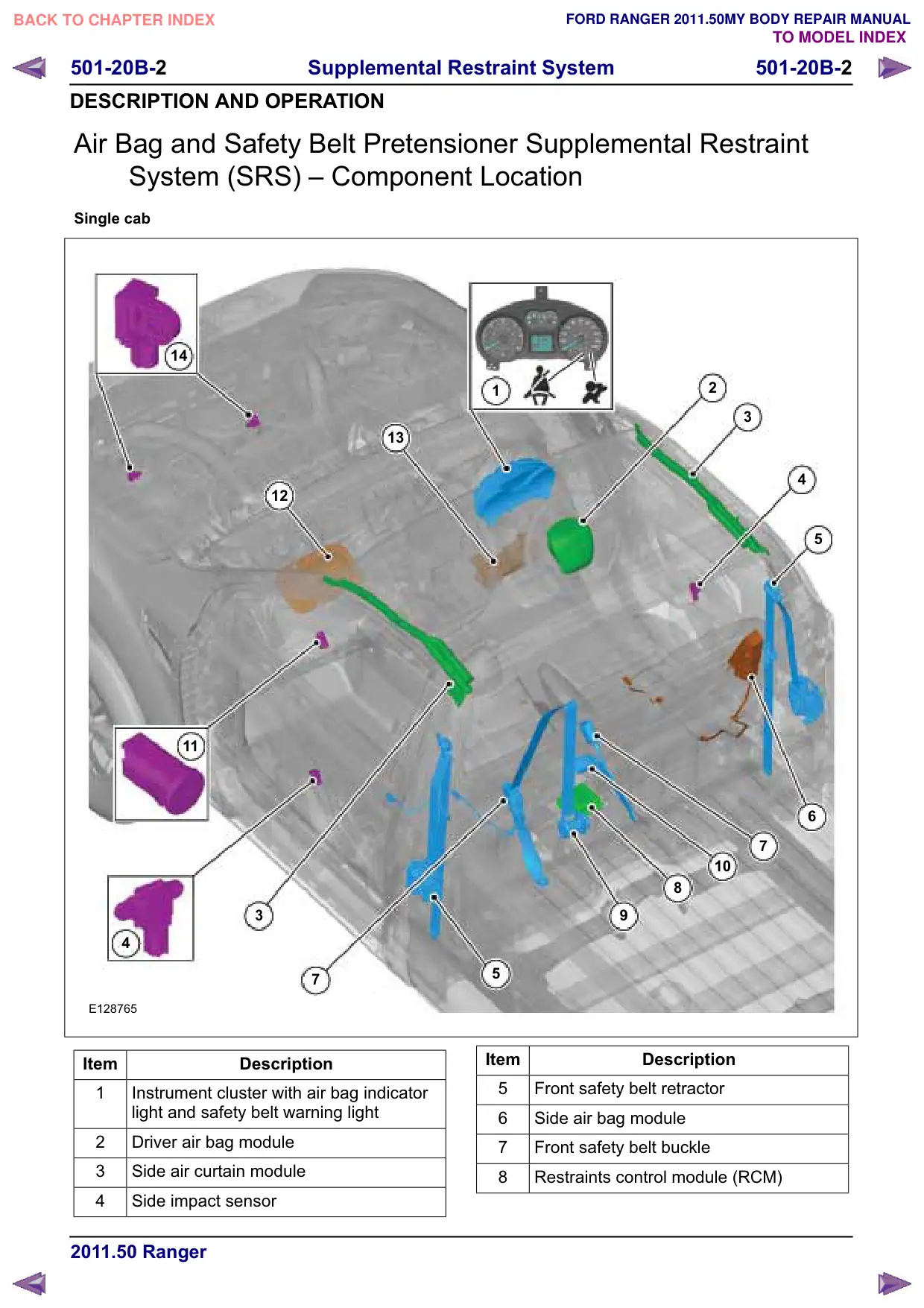
Air Bag and Safety Belt Pretensioner Supplemental Restraint
System (SRS) œ Component Location
Single cab
14
13
12
11
3
4
7
E128765
Item
Description
1
Instrument cluster with air bag indicator
light and safety belt warning light
2
Driver air bag module
3
Side air curtain module
4
Side impact sensor
1
2
3
4
5
6
7
10
8
5
Item
Description
5
Front safety belt retractor
6
Side air bag module
7
Front safety belt buckle
8
Restraints control module (RCM)
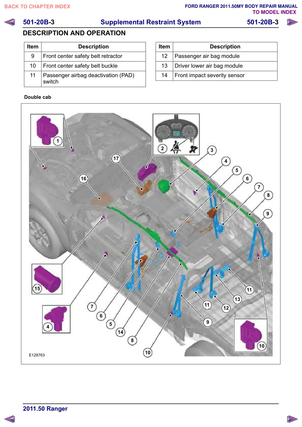
501-20B-4
Supplemental Restraint System
501-20B-4
DESCRIPTION AND OPERATION
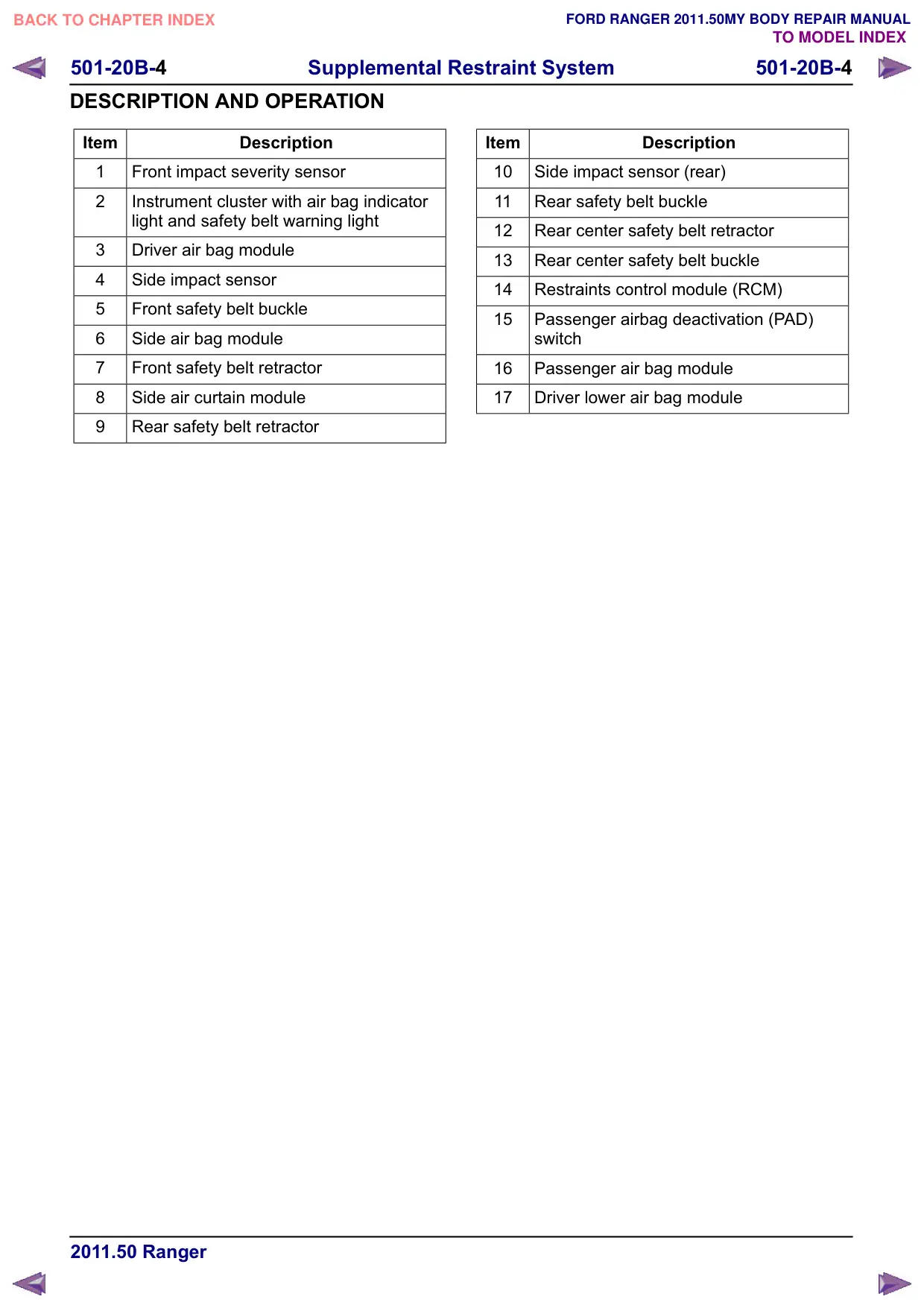
Item
Description
1
Front impact severity sensor
2
Instrument cluster with air bag indicator
light and safety belt warning light
3
Driver air bag module
4
Side impact sensor
5
Front safety belt buckle
6
Side air bag module
7
Front safety belt retractor
8
Side air curtain module
Rear safety belt retractor
Item
Description
10
Side impact sensor (rear)
11
Rear safety belt buckle
12
Rear center safety belt retractor
13
Rear center safety belt buckle
14
Restraints control module (RCM)
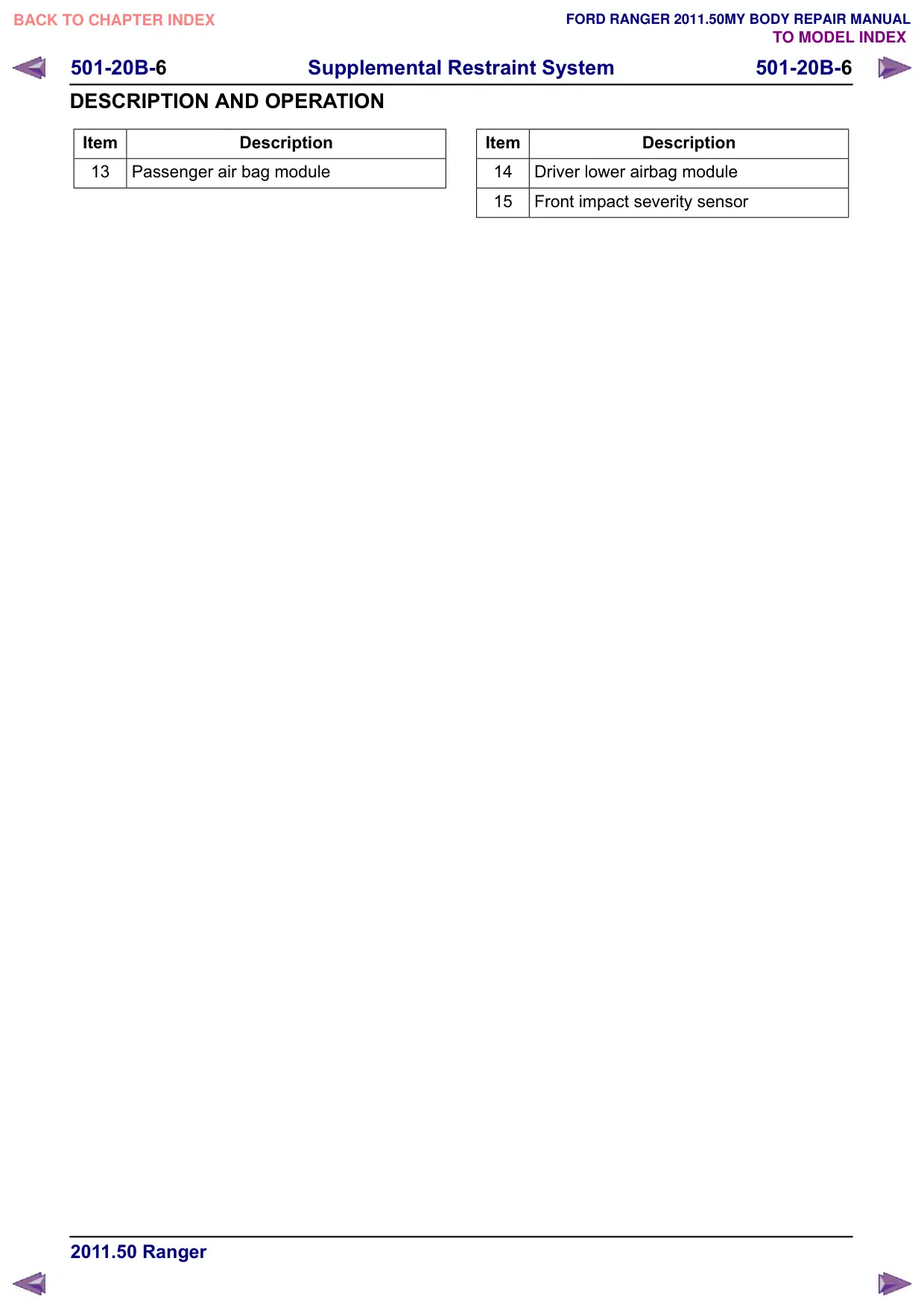
15
Passenger airbag deactivation (PAD)
switch
16
Passenger air bag module
17
Driver lower air bag module
501-20B-5
Supplemental Restraint System
501-20B-5
DESCRIPTION AND OPERATION
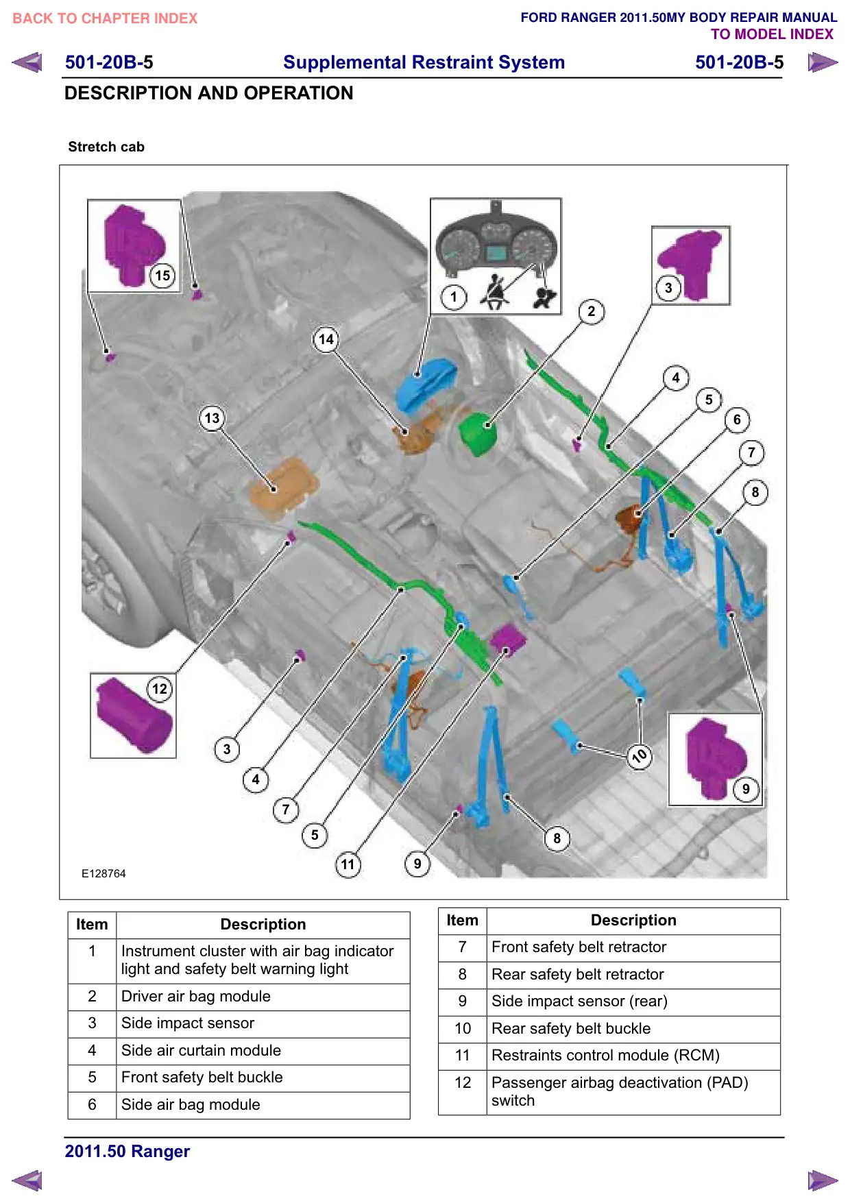
Stretch cab
15
14
13
12
3
4
7
5
11
E128764
Item
Description
1
Instrument cluster with air bag indicator
light and safety belt warning light
2
Driver air bag module
3
Side impact sensor
4
Side air curtain module
5
Front safety belt buckle
6
Side air bag module
3
1
2
4
5
6
7
8
10
8
Item
Description
7
Front safety belt retractor
8
Rear safety belt retractor
Side impact sensor (rear)
10
Rear safety belt buckle
11
Restraints control module (RCM)
12
Passenger airbag deactivation (PAD)
switch
501-20B-7
Supplemental Restraint System
501-20B-7
DESCRIPTION AND OPERATION
Air Bag and Safety Belt Pretensioner Supplemental Restraint
System (SRS)
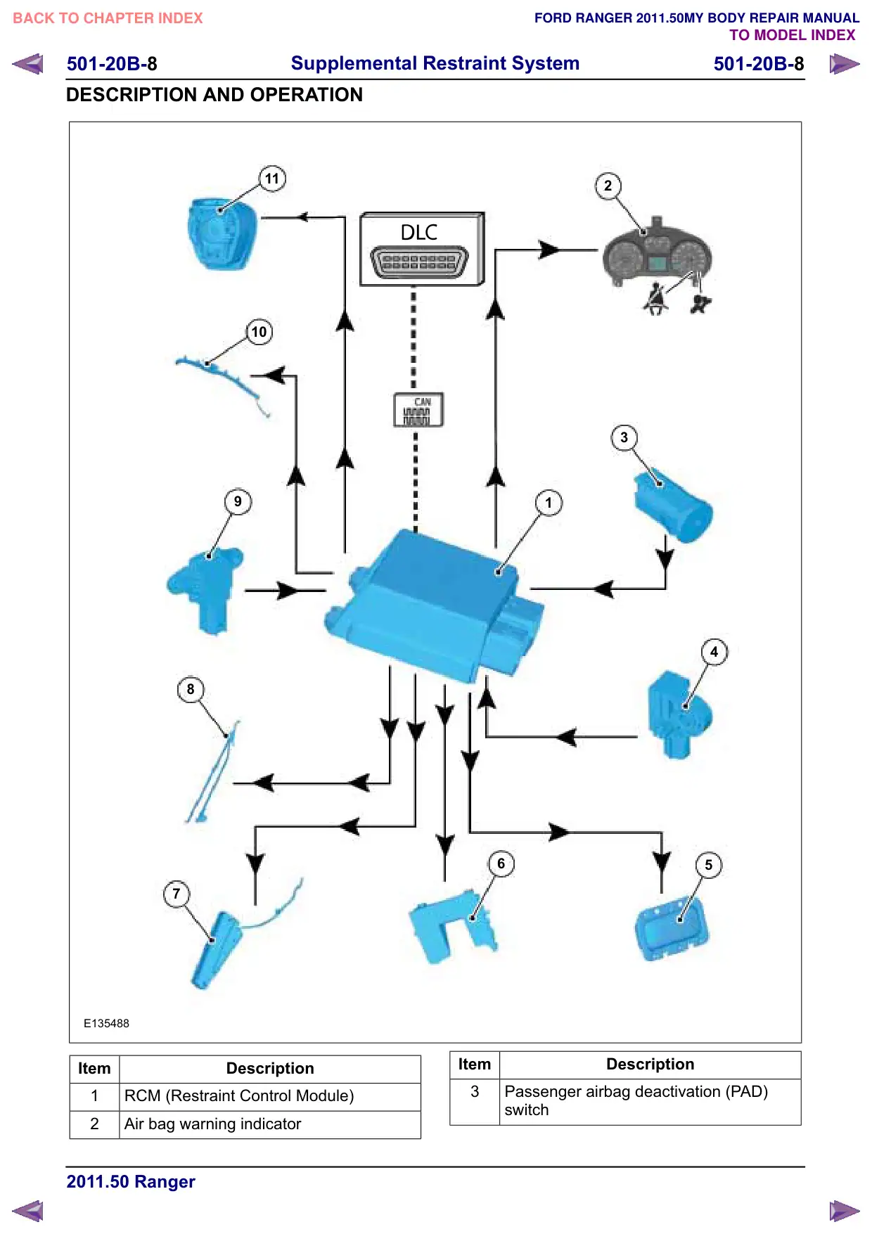
System overview
Click here to view diagrams
501-20B-
Supplemental Restraint System
501-20B-
DESCRIPTION AND OPERATION
Item
Description
4
Front impact severity sensor
5
Passenger air bag module
6
Driver lower airbag module
7
Side airbag module
8
Safety belt retractor and pretensioner
Side impact sensor
10
Side air curtain module
11
Driver airbag module
RCM (Restraint Control Module)
E135477
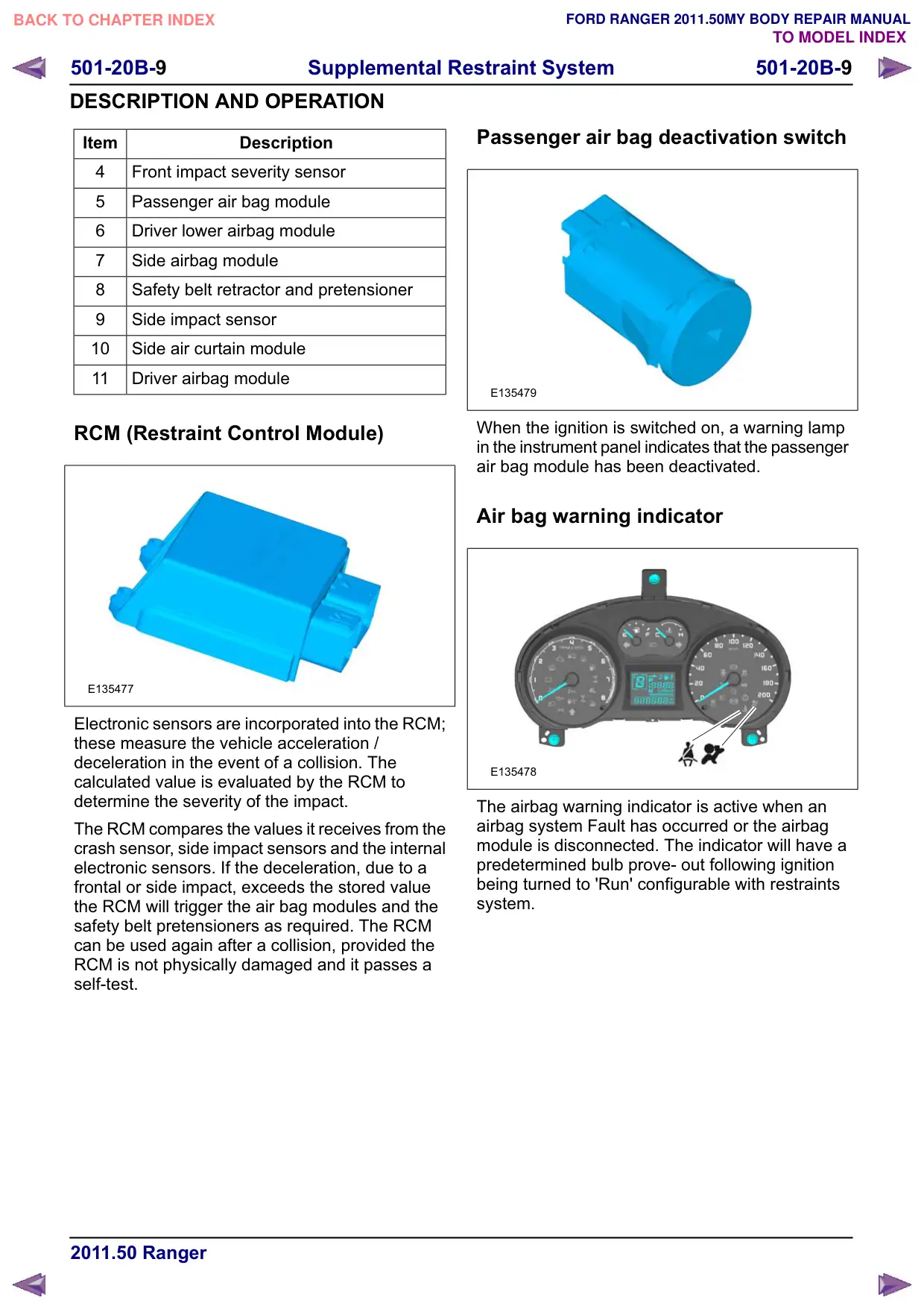
Electronic sensors are incorporated into the RCM;
these measure the vehicle acceleration /
deceleration in the event of a collision. The
calculated value is evaluated by the RCM to
determine the severity of the impact.
The RCM compares the values it receives from the
crash sensor, side impact sensors and the internal
electronic sensors. If the deceleration, due to a
frontal or side impact, exceeds the stored value
the RCM will trigger the air bag modules and the
safety belt pretensioners as required. The RCM
can be used again after a collision, provided the
RCM is not physically damaged and it passes a
self-test.
Passenger air bag deactivation switch
E135479
When the ignition is switched on, a warning lamp
in the instrument panel indicates that the passenger
air bag module has been deactivated.
Air bag warning indicator
E135478
The airbag warning indicator is active when an
airbag system Fault has occurred or the airbag
module is disconnected. The indicator will have a
predetermined bulb prove- out following ignition
being turned to 'Run' configurable with restraints
system.
501-20B-10
Supplemental Restraint System
501-20B-10
DESCRIPTION AND OPERATION
Driver air bag and driver lower air bag
E135480
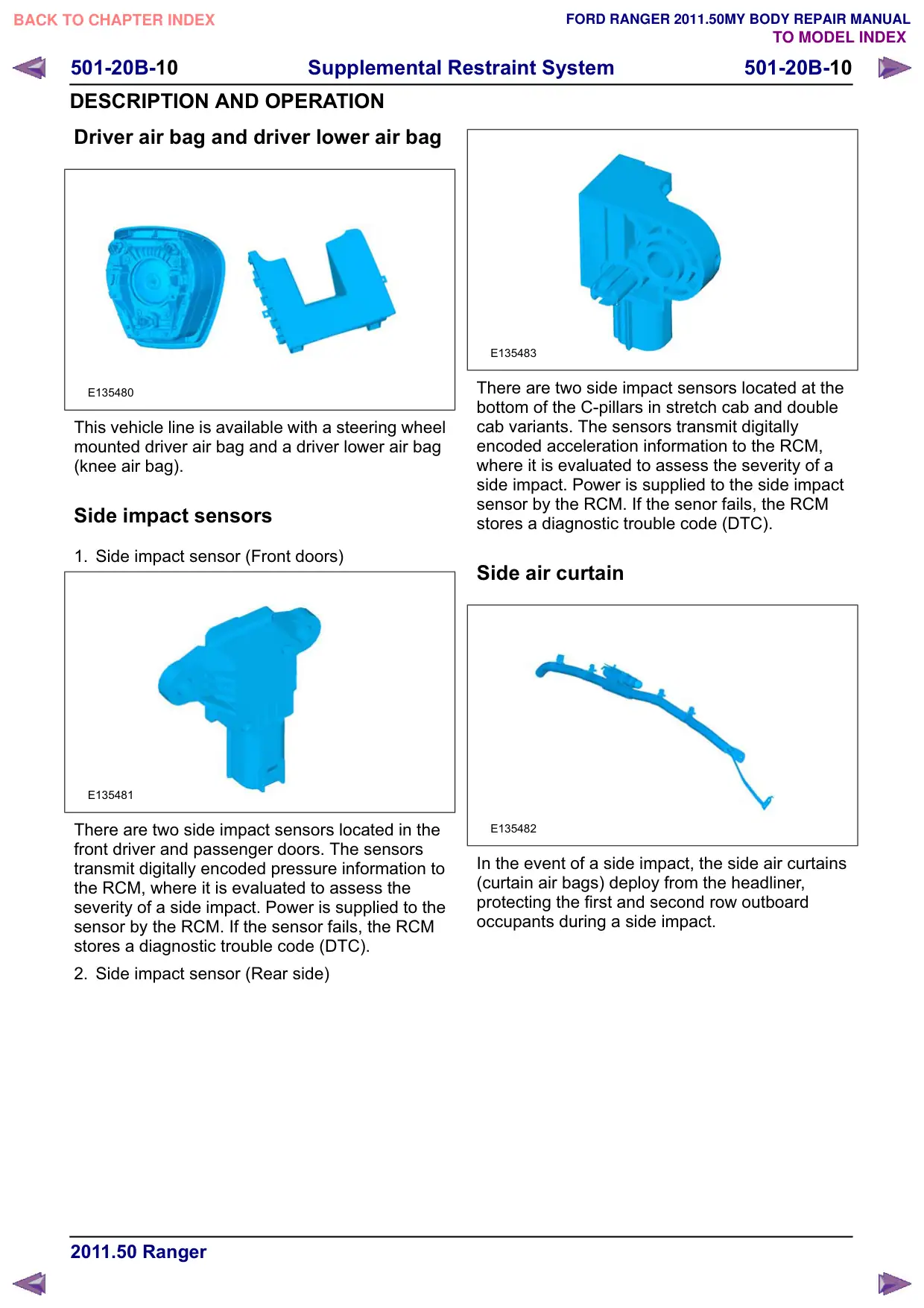
This vehicle line is available with a steering wheel
mounted driver air bag and a driver lower air bag
(knee air bag).
Side impact sensors
1. Side impact sensor (Front doors)
E135481
There are two side impact sensors located in the
front driver and passenger doors. The sensors
transmit digitally encoded pressure information to
the RCM, where it is evaluated to assess the
severity of a side impact. Power is supplied to the
sensor by the RCM. If the sensor fails, the RCM
stores a diagnostic trouble code (DTC).
2. Side impact sensor (Rear side)
E135483
There are two side impact sensors located at the
bottom of the C-pillars in stretch cab and double
cab variants. The sensors transmit digitally
encoded acceleration information to the RCM,
where it is evaluated to assess the severity of a
side impact. Power is supplied to the side impact
sensor by the RCM. If the senor fails, the RCM
stores a diagnostic trouble code (DTC).
Side air curtain
E135482
In the event of a side impact, the side air curtains
(curtain air bags) deploy from the headliner,
protecting the first and second row outboard
occupants during a side impact.
501-20B-11
Supplemental Restraint System
501-20B-11
DESCRIPTION AND OPERATION
Front impact severity sensor
E135483
There are two front impact severity sensors located
at the front of the vehicle, behind the radiator grille.
The sensors transmit digitally encoded acceleration
information to the RCM, where it is evaluated to
assess the severity of a front impact. Power is
supplied to the sensor by the RCM. If the sensor
fails, the RCM stores a diagnostic trouble code
(DTC).
Safety belt retractor and pretensioners
E135484
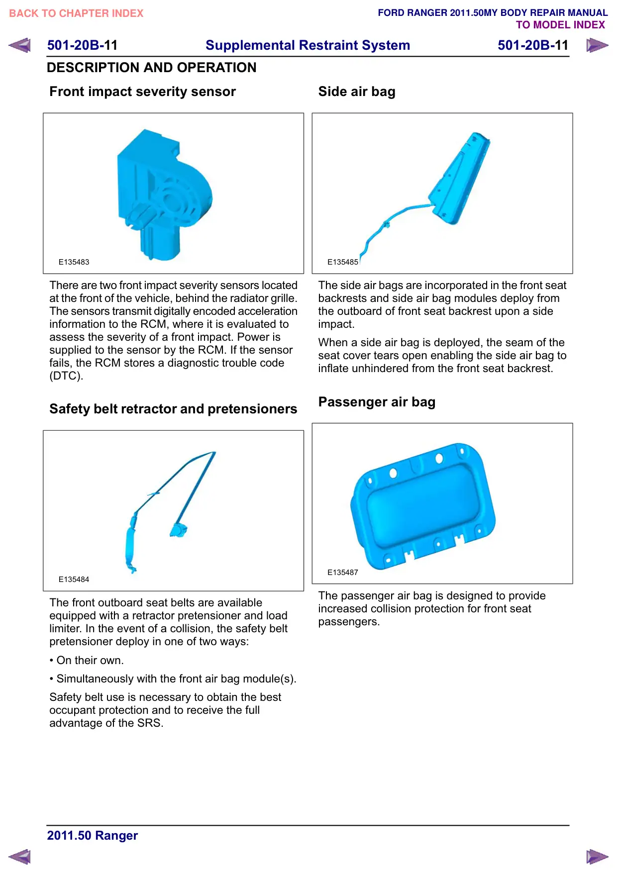
The front outboard seat belts are available
equipped with a retractor pretensioner and load
limiter. In the event of a collision, the safety belt
pretensioner deploy in one of two ways:
• On their own.
• Simultaneously with the front air bag module(s).
Safety belt use is necessary to obtain the best
occupant protection and to receive the full
advantage of the SRS.
Side air bag
E135485
The side air bags are incorporated in the front seat
backrests and side air bag modules deploy from
the outboard of front seat backrest upon a side
impact.
When a side air bag is deployed, the seam of the
seat cover tears open enabling the side air bag to
inflate unhindered from the front seat backrest.
Passenger air bag
E135487
The passenger air bag is designed to provide
increased collision protection for front seat
passengers.
501-20B-12
Supplemental Restraint System
501-20B-12
GENERAL PROCEDURES
Clockspring Adjustment
General Equipment
Adhesive Tape
WARNINGS:
If there is a break between installing the
clockspring and steering wheel rotation
sensor assembly and installing the
steering wheel, the centralizing of the
clockspring must be repeated.
If the centralization of the clockspring is
in doubt, the centralizing of the clockspring
must be repeated.
NOTE: Make sure that the road wheels are in the
straight ahead position.
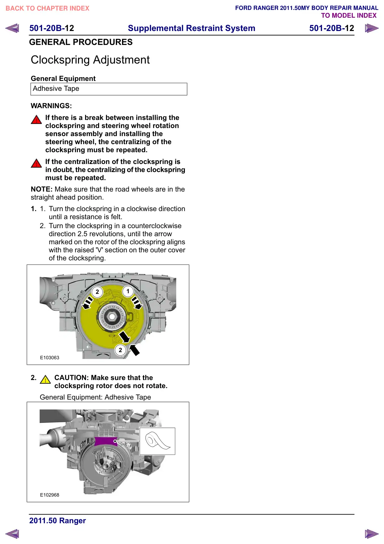
1.
1.
Turn the clockspring in a clockwise direction
until a resistance is felt.
2. Turn the clockspring in a counterclockwise
direction 2.5 revolutions, until the arrow
marked on the rotor of the clockspring aligns
with the raised 'V' section on the outer cover
of the clockspring.
2
1
2
E103063
2.
CAUTION: Make sure that the
clockspring rotor does not rotate.
General Equipment: Adhesive Tape
E102968
501-20B-13
Supplemental Restraint System
501-20B-13
GENERAL PROCEDURES
Deployed Air Bag Disposal
WARNING: After deployment, the air bag
module surface may contain deposits of
sodium hydroxide, a product of the gas
generate combustion, that is irritating to
the skin. Use protective gloves when
handling any deployed air bag module.
Failure to follow this instruction may result
in personal injury.
1. Remove the deployed air bag module(s). For
additional information, refer to the relevant
procedure in this section.
2. Seal the deployed air bag module(s) in the
packaging from the new air bag module(s)
or a suitable polythene bag, and then
dispose of in accordance with local
contaminated waste regulations.
501-20B-14
Supplemental Restraint System
501-20B-14
GENERAL PROCEDURES
Scrapped Vehicle Air Bag and Safety Belt Pretensioner Disposal
- In-Vehicle Disposal
Special Tool(s)
418-143
Adapter Box (AC)
418-S055C
Test and Deployment Lead,
Air Bag/Pyrotechnic Safety
Belt
Disposal
WARNINGS:
To avoid accidental deployment, the
restraints control module (RCM) backup
power supply must be depleted. Wait at
least one minute after disconnecting the
battery ground cable(s) before
commencing any repair or adjustment to
the supplemental restraint system (SRS),
or any component(s) adjacent to the SRS
sensors. Failure to follow these
instructions may result in personal injury.
To minimize the possibility of premature
deployment, do not use radio key code
savers when working on the SRS. Failure
to follow this instruction may result in
personal injury.
Before deploying the air bag module or
safety belt pretensioner pyrotechnic make
sure that all personnel in the vicinity are
aware that a loud noise (bang) is about to
occur. Do not let anybody approach closer
than 6 meters. Failure to follow this
instruction may result in personal injury.
The air bag module or the safety belt
pretensioner should not be handled
immediately following deployment as the
air bag module will be very hot. Failure to
follow this instruction may result in
personal injury.
After deployment, the inflator(s) becomes
inert, direct contact to the skin or eyes of
any free pyrotechnic residues should be
avoided. Failure to follow this instruction
may result in personal injury.
Always wear gloves and safety glasses
when handling deployed air bag modules
and safety belt pretensioners, Failure to
follow this instruction may result in
personal injury.
If the air bag module or safety belt
pretensioner pyrotechnic residue should
contact the eyes, wash the eyes with clean
water and seek medical assistance. Failure
to follow this instruction may result in
personal injury.
If a large amount of air bag or safety belt
pretensioner pyrotechnic residue is
inhaled, seek medical assistance. Failure
to follow this instruction may result in
personal injury.
3. Refer to: Battery Disconnect and Connect
(414-01 Battery, Mounting and Cables,
General Procedures).
4. Refer to: Floor Console (501-12 Instrument
Panel and Console, Removal and Installation).
Refer to: Floor Console Extension - Vehicles
With: Center Armrest (501-12, Removal and
Installation).
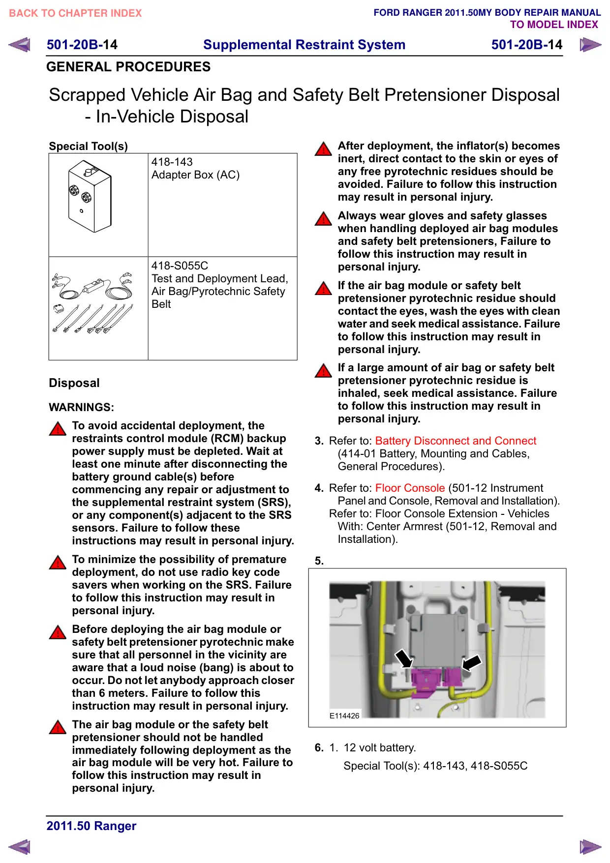
5.
E114426
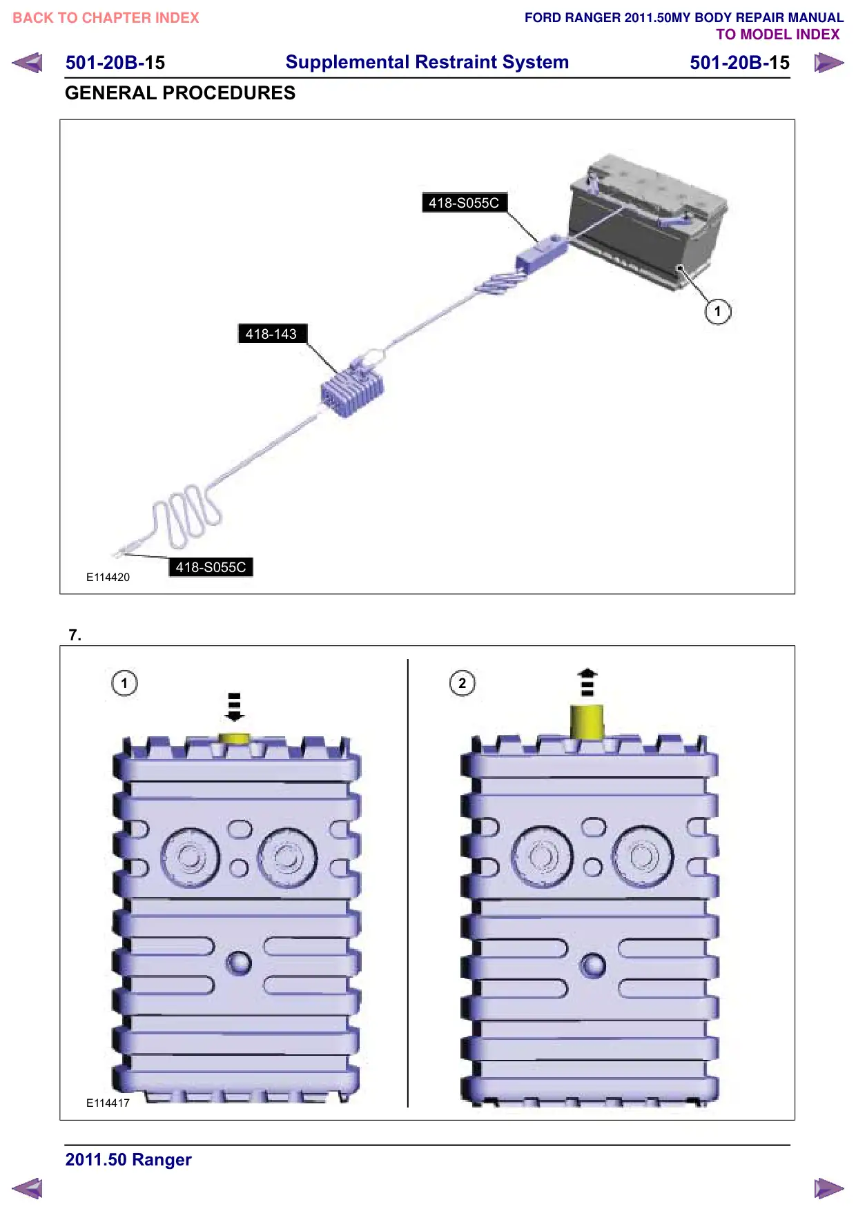
6.
1.
12 volt battery.
Special Tool(s): 418-143, 418-S055C
501-20B-16
Supplemental Restraint System
501-20B-16
GENERAL PROCEDURES
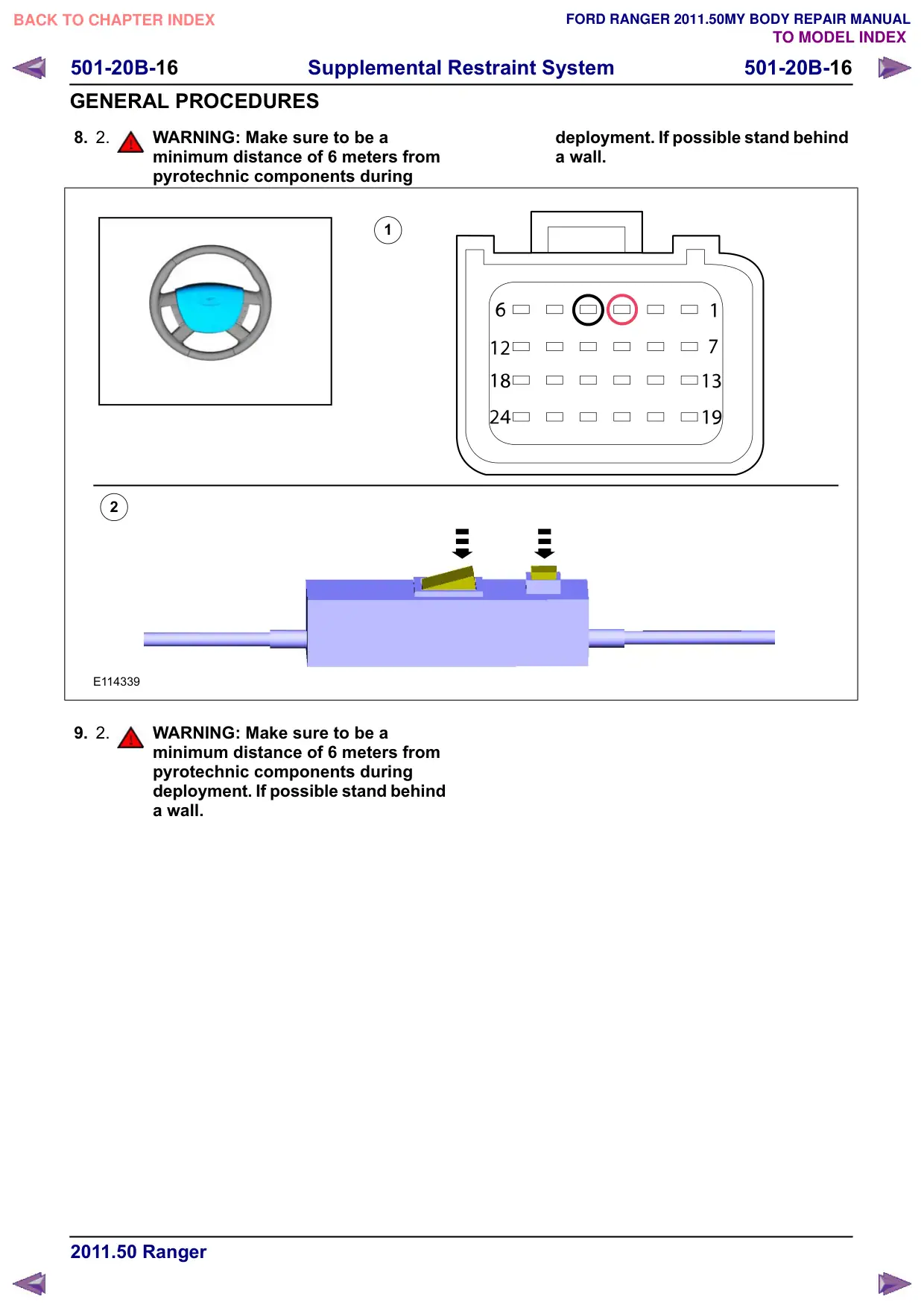
8. 2.
WARNING: Make sure to be a
minimum distance of 6 meters from
pyrotechnic components during
1
2
E114339
9. 2.
WARNING: Make sure to be a
minimum distance of 6 meters from
pyrotechnic components during
deployment. If possible stand behind
a wall.
deployment. If possible stand behind
a wall.
501-20B-17
Supplemental Restraint System
501-20B-17
GENERAL PROCEDURES
1
2
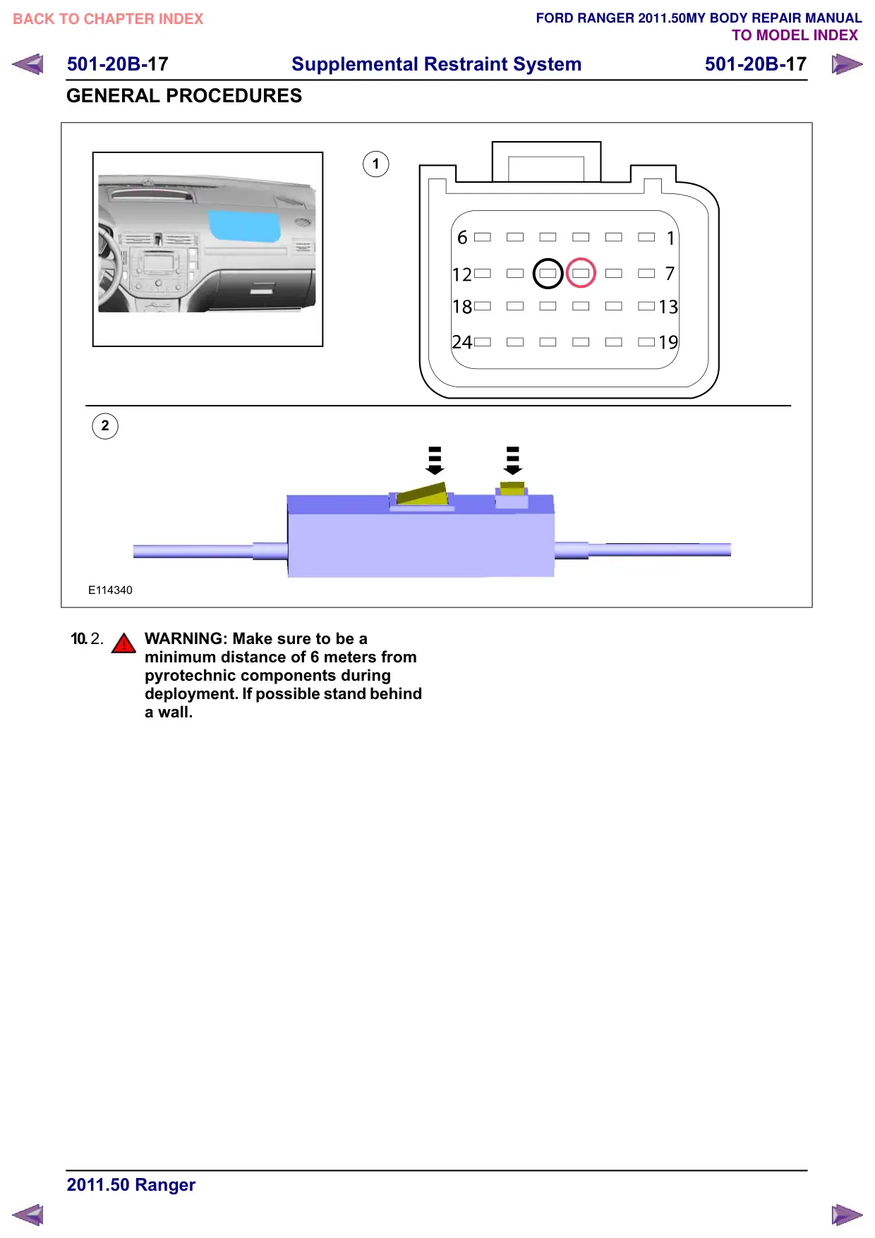
E114340
10. 2.
WARNING: Make sure to be a
minimum distance of 6 meters from
pyrotechnic components during
deployment. If possible stand behind
a wall.
501-20B-18
Supplemental Restraint System
501-20B-18
GENERAL PROCEDURES
1
2
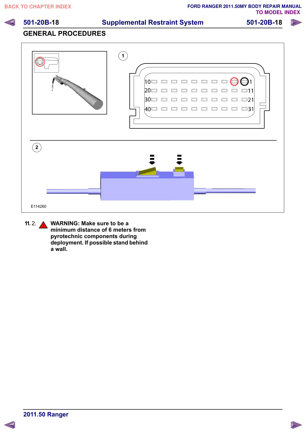
E114260
11. 2.
WARNING: Make sure to be a
minimum distance of 6 meters from
pyrotechnic components during
deployment. If possible stand behind
a wall.
501-20B-19
Supplemental Restraint System
501-20B-19
GENERAL PROCEDURES
1
2
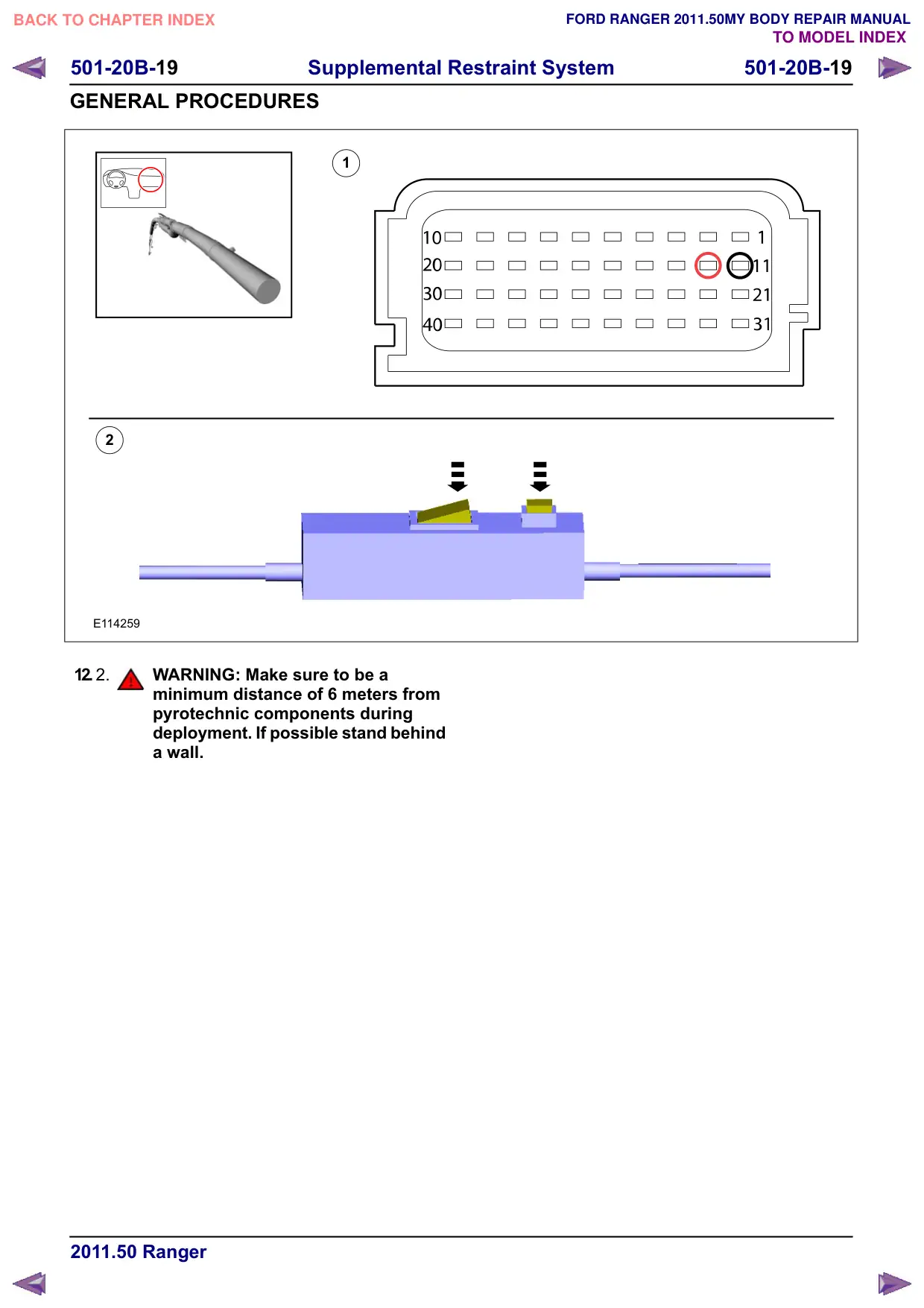
E114259
12. 2.
WARNING: Make sure to be a
minimum distance of 6 meters from
pyrotechnic components during
deployment. If possible stand behind
a wall.
501-20B-20
Supplemental Restraint System
501-20B-20
GENERAL PROCEDURES
1
2
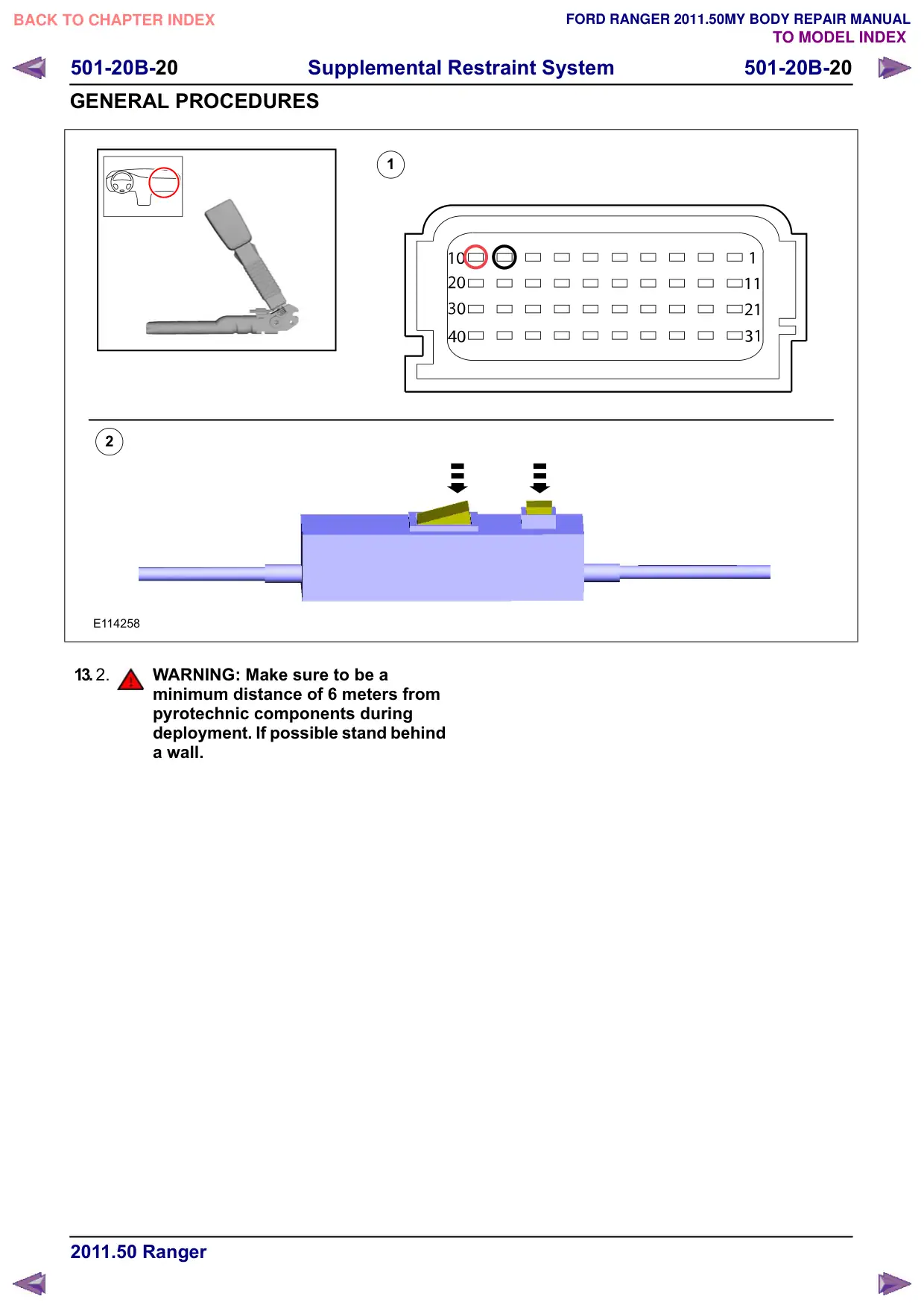
E114258
13. 2.
WARNING: Make sure to be a
minimum distance of 6 meters from
pyrotechnic components during
deployment. If possible stand behind
a wall.
501-20B-21
Supplemental Restraint System
501-20B-21
GENERAL PROCEDURES
1
2
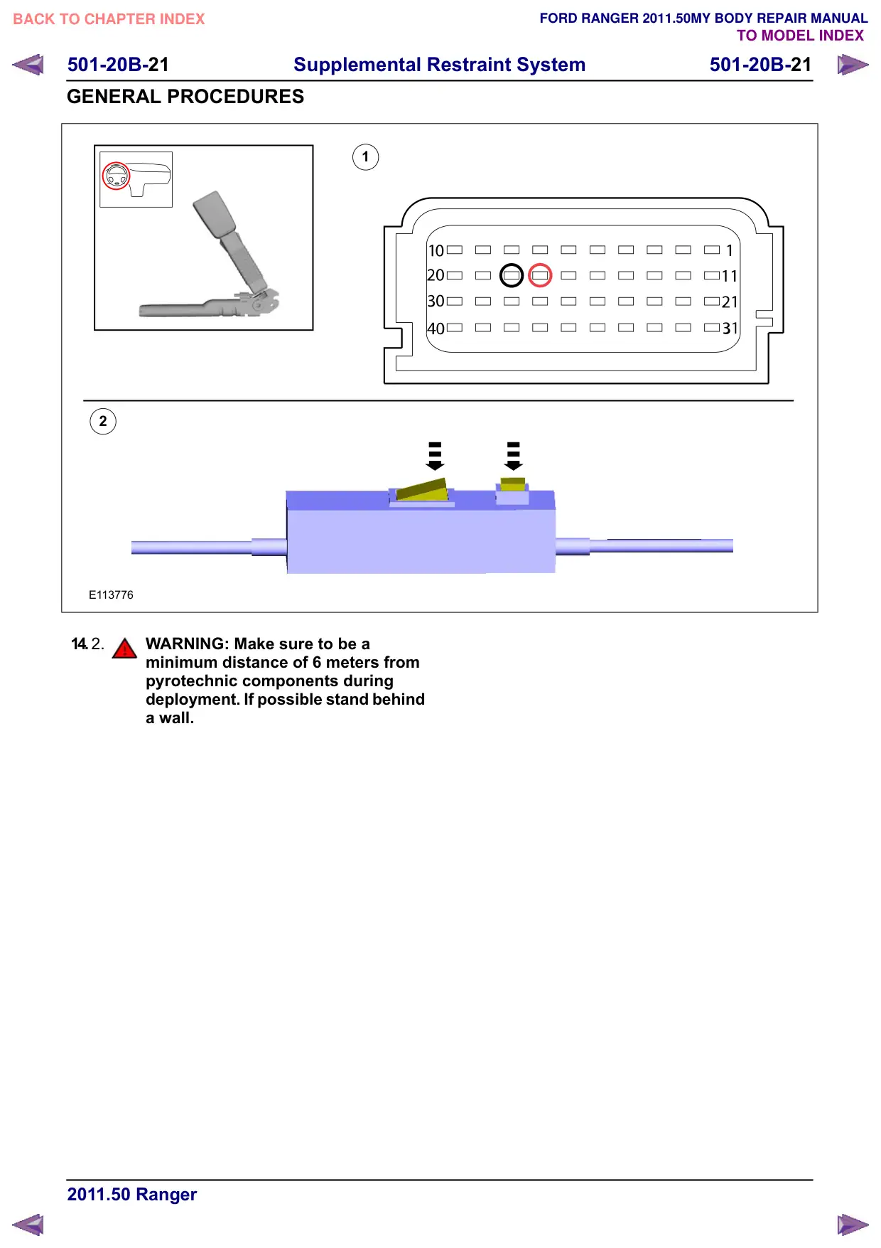
E113776
14. 2.
WARNING: Make sure to be a
minimum distance of 6 meters from
pyrotechnic components during
deployment. If possible stand behind
a wall.
501-20B-22
Supplemental Restraint System
501-20B-22
GENERAL PROCEDURES
1
2
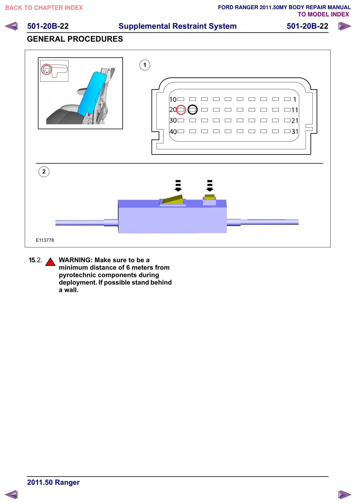
E113778
15. 2.
WARNING: Make sure to be a
minimum distance of 6 meters from
pyrotechnic components during
deployment. If possible stand behind
a wall.
501-20B-23
Supplemental Restraint System
501-20B-23
GENERAL PROCEDURES
1
2
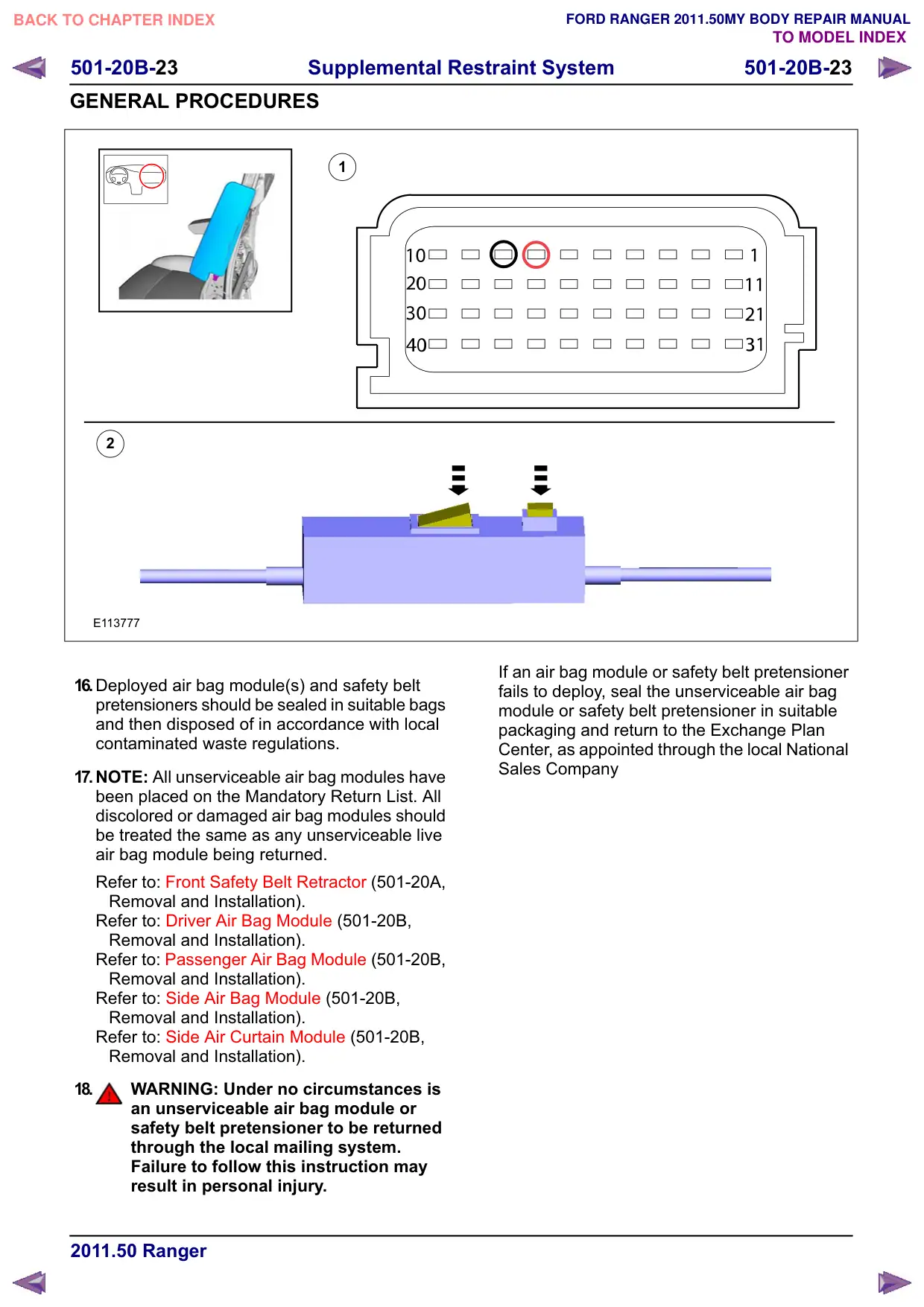
E113777
16.Deployed air bag module(s) and safety belt
pretensioners should be sealed in suitable bags
and then disposed of in accordance with local
contaminated waste regulations.
17.NOTE: All unserviceable air bag modules have
been placed on the Mandatory Return List. All
discolored or damaged air bag modules should
be treated the same as any unserviceable live
air bag module being returned.
Refer to: Front Safety Belt Retractor (501-20A,
Removal and Installation).
Refer to: Driver Air Bag Module (501-20B,
Removal and Installation).
Refer to: Passenger Air Bag Module (501-20B,
Removal and Installation).
Refer to: Side Air Bag Module (501-20B,
Removal and Installation).
Refer to: Side Air Curtain Module (501-20B,
Removal and Installation).
18.
WARNING: Under no circumstances is
an unserviceable air bag module or
safety belt pretensioner to be returned
through the local mailing system.
Failure to follow this instruction may
result in personal injury.
If an air bag module or safety belt pretensioner
fails to deploy, seal the unserviceable air bag
module or safety belt pretensioner in suitable
packaging and return to the Exchange Plan
Center, as appointed through the local National
Sales Company
501-20B-24
Supplemental Restraint System
501-20B-24
GENERAL PROCEDURES
Unserviceable Air Bag Disposal
1. WARNINGS:
To minimize the possibility of injury in
the event of premature deployment, always
carry a live air bag module with the bag and
trim cover pointed away from the body.
Failure to follow this instruction may result
in personal injury.
To prevent premature deployment, live
air bag modules must only be placed on work
benches which have been ground bonded.
Failure to follow this instruction may result
in personal injury.
NOTE: All unserviceable air bag modules have
been placed on the Mandatory Return List. All
discolored or damaged air bag modules should be
treated the same as any unserviceable live air bag
module being returned.
Remove the unserviceable air bag module.
For additional information, refer to the
relevant procedure in this section.
2.
WARNING: Under no circumstances is
an unserviceable air bag module(s) to be
returned through the local mailing system.
Failure to follow this instruction may result
in personal injury.
Seal the unserviceable air bag module(s) in
the packaging from the new air bag
module(s) and address to the appropriate
manufacturer. The package should then be
forwarded to the Exchange Plan Center (as
appointed through the national sales
company) who will arrange forwarding to the
manufacturer.
3. NOTE: Autoliv air bag modules and seat belt
pretensioners.
Autoliv Gmbh, Theodor Heuss Strasse 2,
85221, Dachau, Germany.
4. NOTE: TRW air bag modules.
TRW Occupant Restraint Systems, FAO Rene
Getto, Industriestr 20, 73551, Aldorf,
Germany.
5. NOTE: TRW seat belt pretensioners.
TRW Occupant Restraint Systems, FAO
Helmut Goss, Industriestr 20, 73551, Aldorf,
Germany.
6. NOTE: Takata Petri air bag modules.
Takata Petri AG, Grossostheimer Strasse
223, D-63741 Aschaffenburg, (Supplier Code
P790M) Germany.
501-20B-26
Supplemental Restraint System
501-20B-26
REMOVAL AND INSTALLATION
Driver Air Bag Module
General Equipment
Flat Headed Screw Driver
Removal
WARNING: The supplemental restraint
system (SRS) is active for a certain length
of time after the power supply has been
disconnected. Wait for a minimum of 3
minutes before disconnecting or removing
any SRS components.
NOTE: Removal steps in this procedure may
contain installation details.
1. Refer to: Supplemental Restraint System (SRS)
Health and Safety Precautions (100-00
General Information, Description and
Operation).
2. Refer to: Battery Disconnect and Connect
(414-01 Battery, Mounting and Cables,
General Procedures).
3. NOTE: Make sure that the road wheels are in
straight ahead position.
E127474
4. Depending on the vehicle variant, steering
wheels with a different design for cut marks can
be fitted.
E127475
5. General Equipment: Flat Headed Screw Driver
2
2
1
1
E127476
501-20B-28
Supplemental Restraint System
501-20B-28
REMOVAL AND INSTALLATION
Passenger Air Bag Module
Removal
WARNING: The supplemental restraint
system (SRS) is active for a certain length
of time after the power supply has been
disconnected. Wait for a minimum of 3
minutes before disconnecting or removing
any SRS components.
NOTE: Removal steps in this procedure may
contain installation details.
1. Refer to: Supplemental Restraint System (SRS)
Health and Safety Precautions (100-00
General Information, Description and
Operation).
Refer to: Battery Disconnect and Connect
(414-01 Battery, Mounting and Cables,
General Procedures).
2. Refer to: Glove Compartment - Removal
(501-12 Instrument Panel and Console,
Removal and Installation).
3.
x6
E133578
4. Torque: 7 Nm
x2
E140194
5. NOTE: Take extra care when handling the
component.
Torque: 6 Nm
1
2
x6
E140195
Installation
1. To install, reverse the removal procedure.
501-20B-29
Supplemental Restraint System
501-20B-29
REMOVAL AND INSTALLATION
Driver Lower Air Bag Module
Removal
WARNINGS:
The supplemental restraint system (SRS)
is active for a certain length of time after
the power supply has been disconnected.
Wait for a minimum of 3 minutes before
disconnecting or removing any SRS
components.
Make sure that the vehicle electrical
system is fully depowered and no other
power source is connected.
NOTE: Removal steps in this procedure may
contain installation details.
1. Refer to: Supplemental Restraint System (SRS)
Health and Safety Precautions (100-00
General Information, Description and
Operation).
2. Refer to: Battery Disconnect and Connect
(414-01 Battery, Mounting and Cables,
General Procedures).
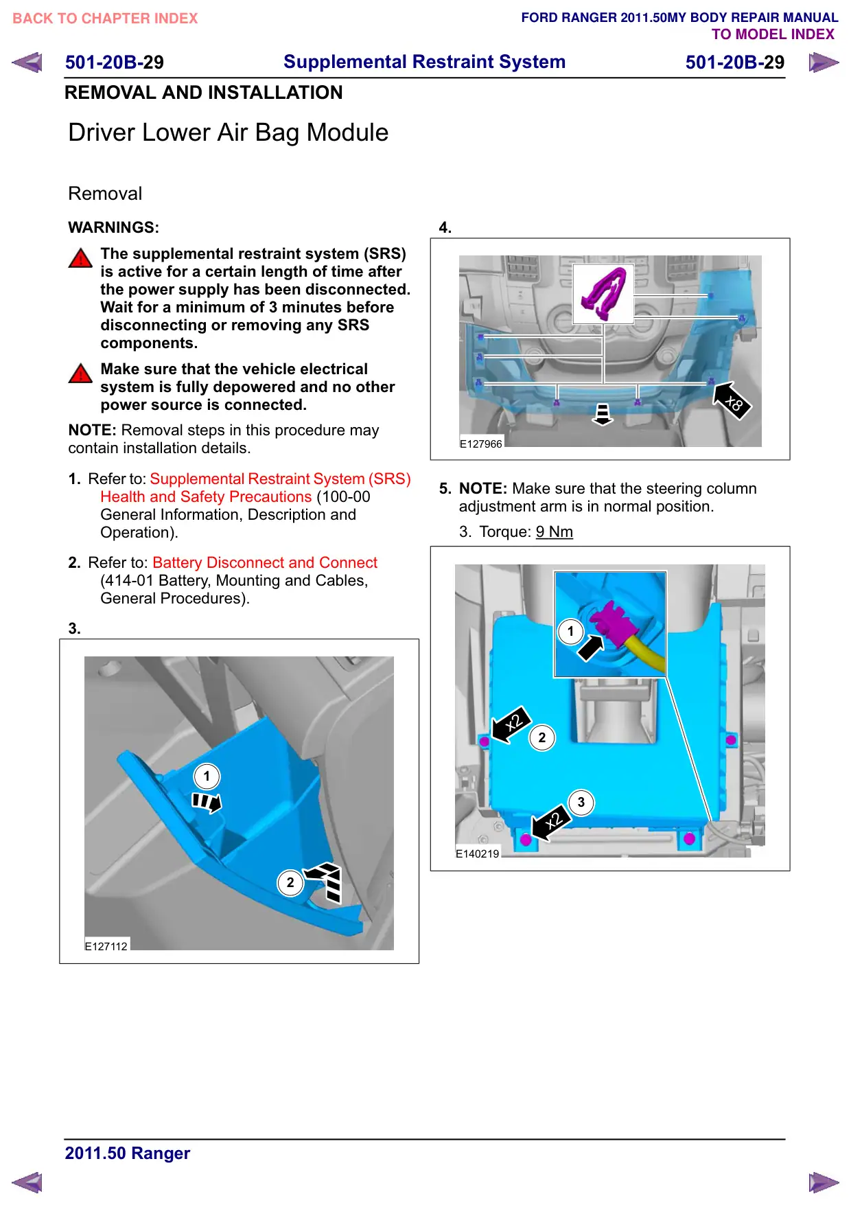
3.
1
2
E127112
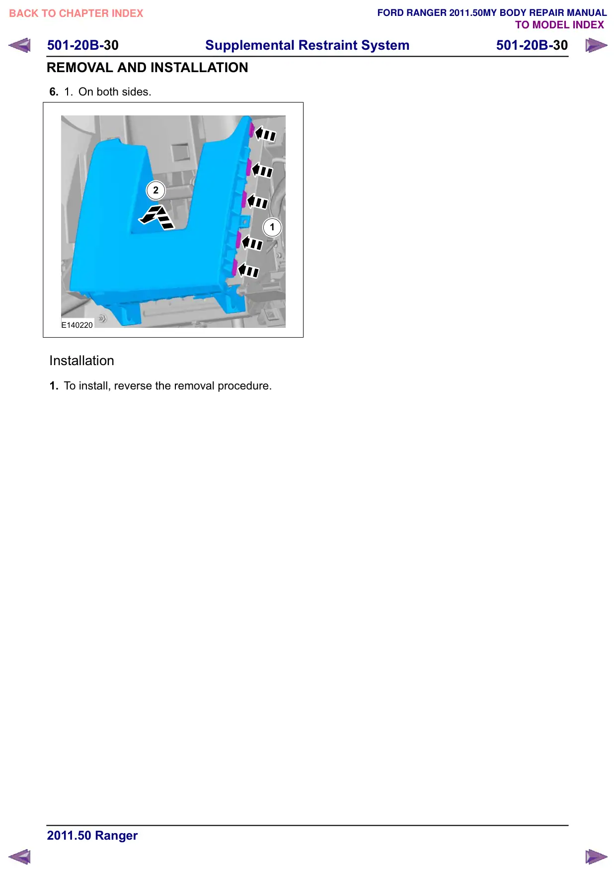
4.
x8
E127966
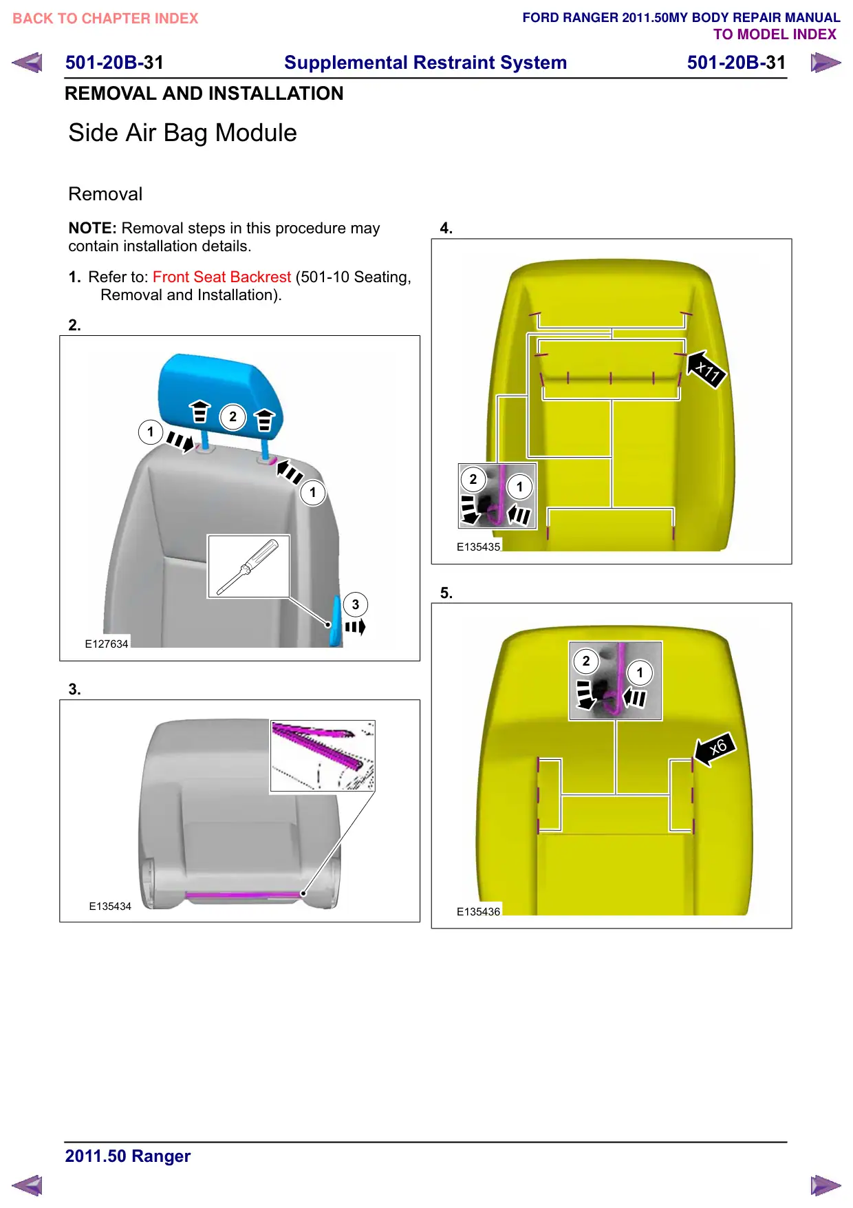
5. NOTE: Make sure that the steering column
adjustment arm is in normal position.
3. Torque: 9 Nm
1
x2
2
3
x2
E140219
501-20B-30
Supplemental Restraint System
501-20B-30
REMOVAL AND INSTALLATION
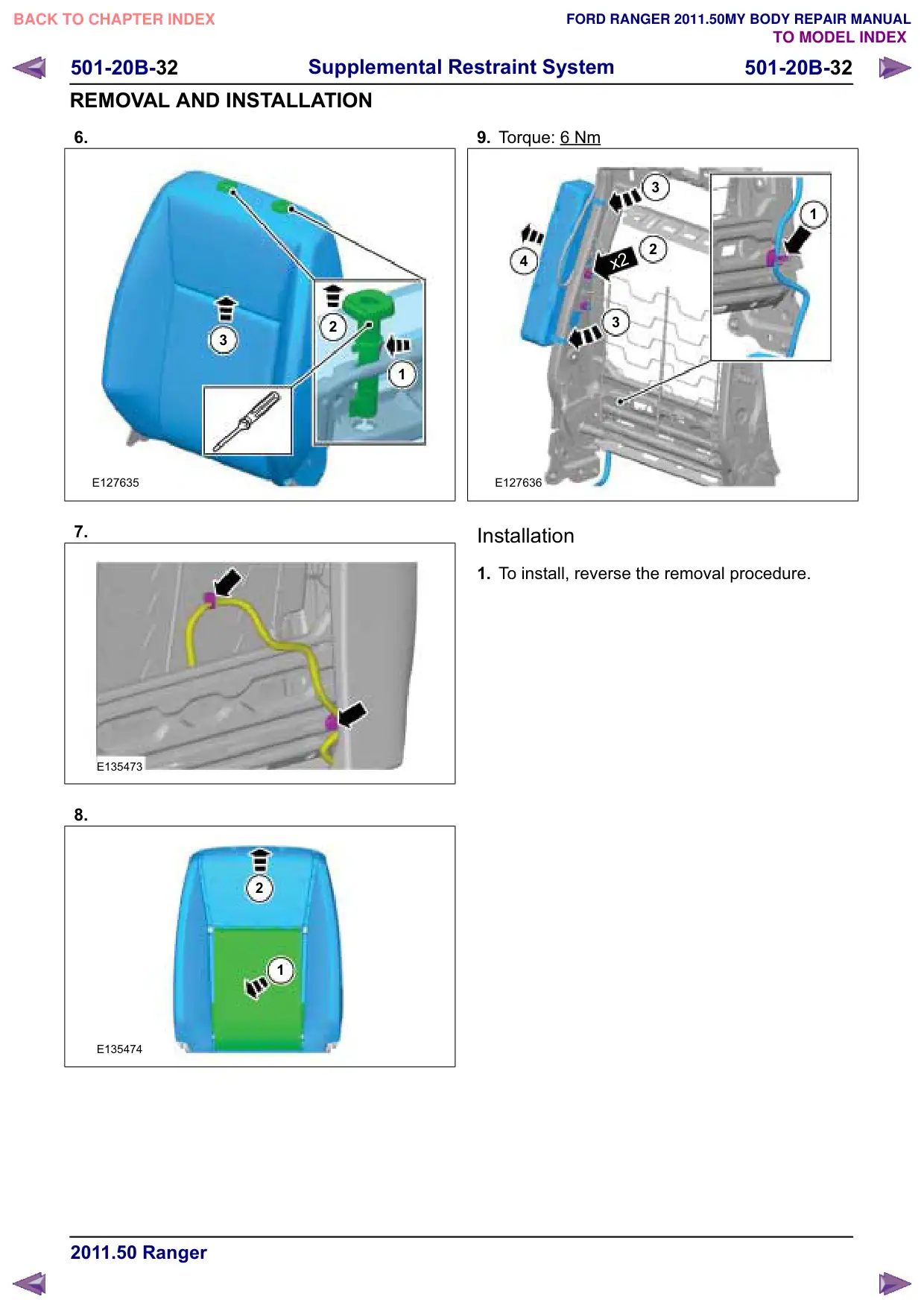
6.
1.
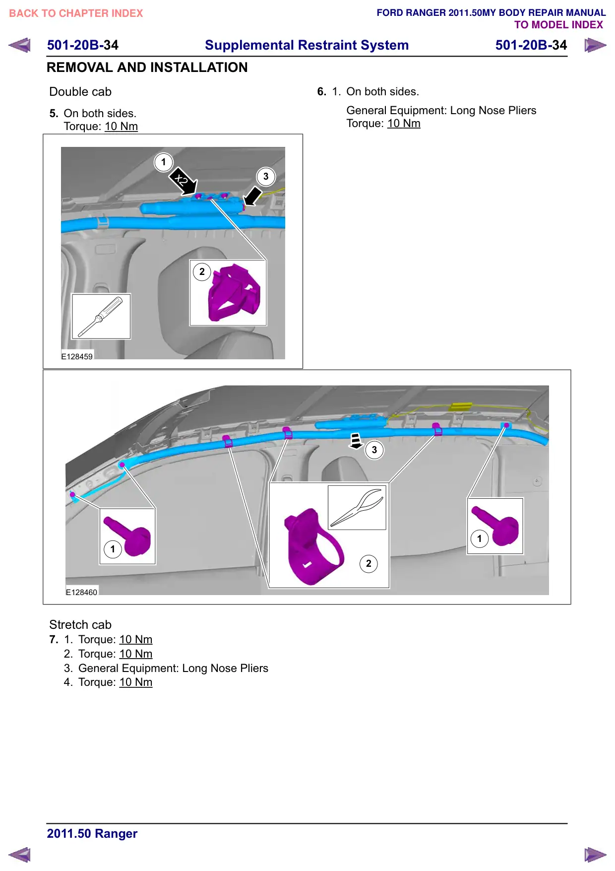
On both sides.
2
1
E140220
Installation
1. To install, reverse the removal procedure.
501-20B-31
Supplemental Restraint System
501-20B-31
REMOVAL AND INSTALLATION
Side Air Bag Module
Removal
NOTE: Removal steps in this procedure may
contain installation details.
1. Refer to: Front Seat Backrest (501-10 Seating,
Removal and Installation).
2.
2
1
1
3
E127634
3.
E135434
4.
x11
2
1
E135435
5.
2
1
x6
E135436
501-20B-33
Supplemental Restraint System
501-20B-33
REMOVAL AND INSTALLATION
Side Air Curtain Module
General Equipment
Long Nose Pliers
Removal
WARNING: The supplemental restraint
system (SRS) is active for a certain length
of time after the power supply has been
disconnected. Wait for a minimum of 3
minutes before disconnecting or removing
any SRS components.
NOTE: Removal steps in this procedure may
contain installation details.
2
1
E128461
1. Refer to: Supplemental Restraint System (SRS)
Health and Safety Precautions (100-00
General Information, Description and
Operation).
2. Refer to: Battery Disconnect and Connect
(414-01 Battery, Mounting and Cables,
General Procedures).
3. Refer to: Headliner (501-05 Interior Trim and
Ornamentation, Removal and Installation).
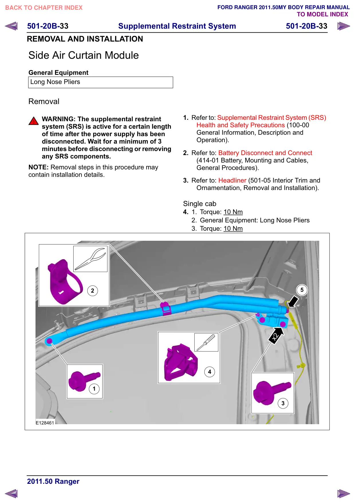
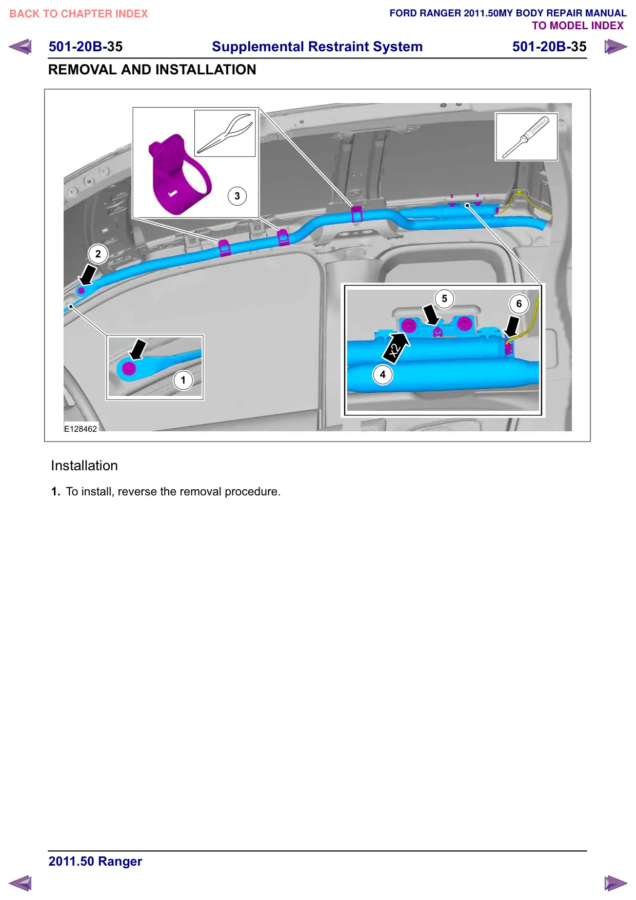
Single cab
4.
1.
Torque: 10 Nm
2. General Equipment: Long Nose Pliers
3. Torque: 10 Nm
5
x2
4
3
501-20B-38
Supplemental Restraint System
501-20B-38
REMOVAL AND INSTALLATION
Restraints Control Module (RCM)
Removal
WARNING: The supplemental restraint
system (SRS) is active for a certain length
of time after the power supply has been
disconnected. Wait for a minimum of 3
minutes before disconnecting or removing
any SRS components.
NOTE: Removal steps in this procedure may
contain installation details.
1. Refer to: Supplemental Restraint System (SRS)
Health and Safety Precautions (100-00
General Information, Description and
Operation).
Refer to: Battery Disconnect and Connect
(414-01 Battery, Mounting and Cables,
General Procedures).
Double cab
2. Refer to: Floor Console - Double Cab (501-12
Instrument Panel and Console, Removal and
Installation).
Stretch cab
3. Refer to: Floor Console - Double Cab (501-12
Instrument Panel and Console, Removal and
Installation).
Single cab
4. Refer to: Floor Console - Single Cab (501-12
Instrument Panel and Console, Removal and
Installation).
Vehicles with front bench seat
5. NOTE: Remove front bench seat only.
Refer to: Front Seat (501-10 Seating, Removal
and Installation).
All vehicles
6. NOTE: Both seats must be move forward before
removing the RCM module.
On both sides.
Torque: 11 Nm
E128552
7.
x2
1
2
E128553
501-20B-40
Supplemental Restraint System
501-20B-40
REMOVAL AND INSTALLATION
Front Impact Severity Sensor
Removal
WARNING: The supplemental restraint
system (SRS) is active for a certain length
of time after the power supply has been
disconnected. Wait for a minimum of 3
minutes before disconnecting or removing
any SRS components.
NOTE: Removal steps in this procedure may
contain installation details.
1. Refer to: Supplemental Restraint System (SRS)
Health and Safety Precautions (100-00
General Information, Description and
Operation).
Refer to: Battery Disconnect and Connect
(414-01 Battery, Mounting and Cables,
General Procedures).
2. Refer to: Lifting (100-02 Jacking and Lifting,
Description and Operation).
3. Torque: 30 Nm
x4
E130132
4. Torque: 10 Nm
E128675
Installation
1. To install, reverse the removal procedure.
501-20B-41
Supplemental Restraint System
501-20B-41
REMOVAL AND INSTALLATION
Side Impact Sensor
Removal
WARNING: The supplemental restraint
system (SRS) is active for a certain length
of time after the power supply has been
disconnected. Wait for a minimum of 3
minutes before disconnecting or removing
any SRS components.
NOTE: Removal steps in this procedure may
contain installation details.
1. Refer to: Supplemental Restraint System (SRS)
Health and Safety Precautions (100-00
General Information, Description and
Operation).
Refer to: Battery Disconnect and Connect
(414-01 Battery, Mounting and Cables,
General Procedures).
Double cab
2. Refer to: C-Pillar Lower Trim Panel (501-05
Interior Trim and Ornamentation, Removal
and Installation).
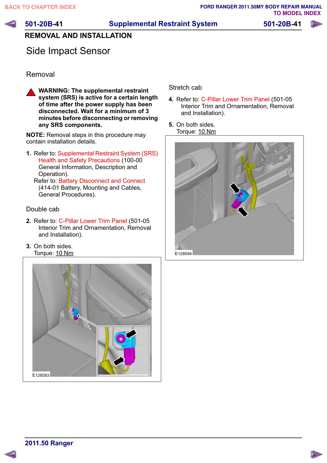
3. On both sides.
Torque: 10 Nm
E128593
Stretch cab
4. Refer to: C-Pillar Lower Trim Panel (501-05
Interior Trim and Ornamentation, Removal
and Installation).
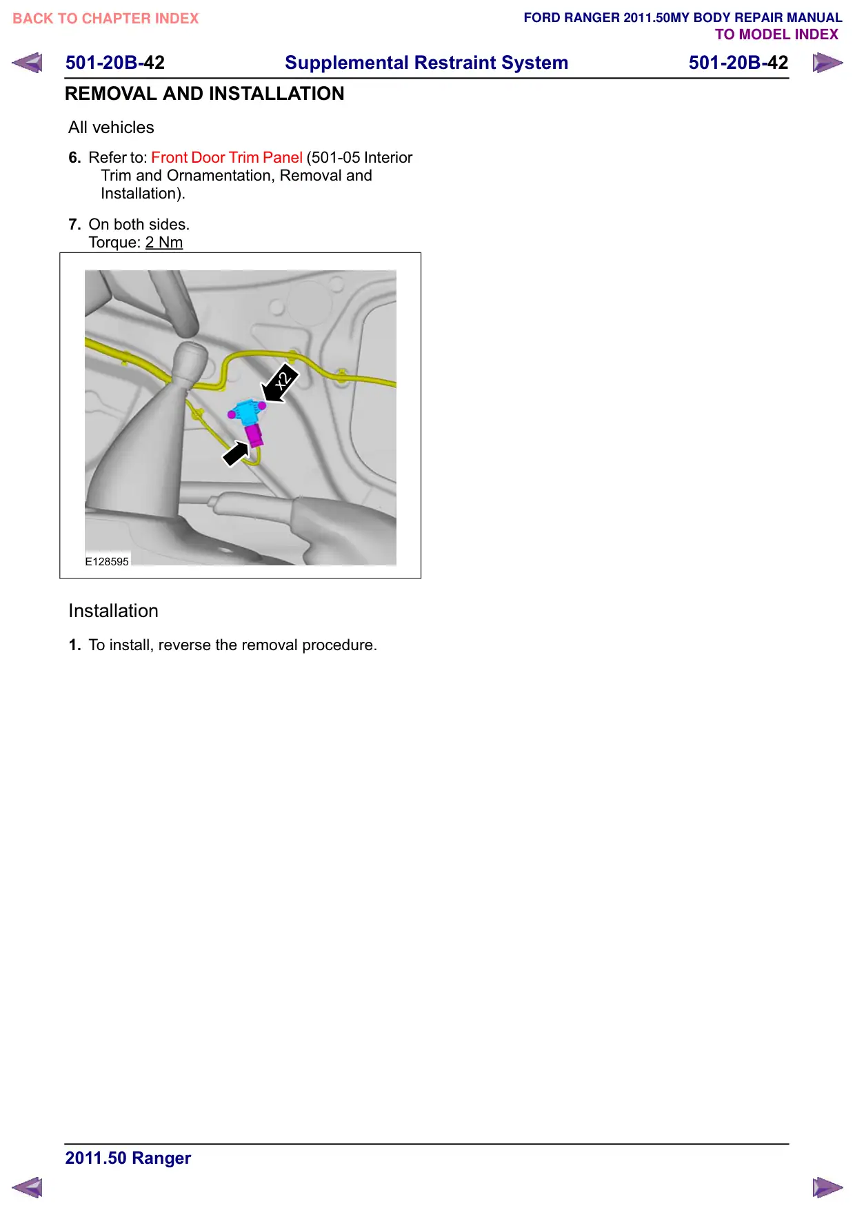
5. On both sides.
Torque: 10 Nm
E128594
501-20B-42
Supplemental Restraint System
501-20B-42
REMOVAL AND INSTALLATION
All vehicles
6. Refer to: Front Door Trim Panel (501-05 Interior
Trim and Ornamentation, Removal and
Installation).
7. On both sides.
Torque: 2 Nm
x2
E128595
Installation
1. To install, reverse the removal procedure.