Front Suspension
204-01-2
204-01-2
DESCRIPTION AND OPERATION
Front Suspension
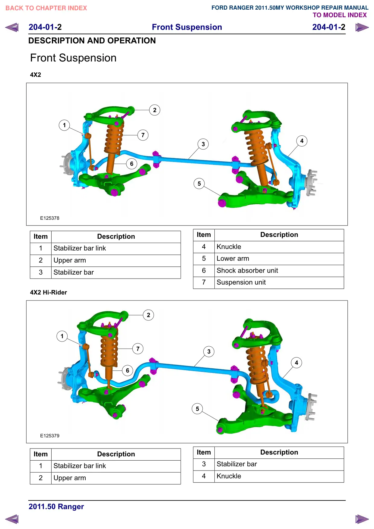
4X2
2
1
7
6
E125378
Item
Description
1
Stabilizer bar link
2
Upper arm
3
Stabilizer bar
4X2 Hi-Rider
2
1
7
6
E125379
Item
Description
1
Stabilizer bar link
2
Upper arm
4
3
5
Item
Description
4
Knuckle
5
Lower arm
6
Shock absorber unit
7
Suspension unit
3
4
5
Item
Description
3
Stabilizer bar
4
Knuckle
Front Suspension
204-01-3
204-01-3
DESCRIPTION AND OPERATION
Item
Description
5
Lower arm
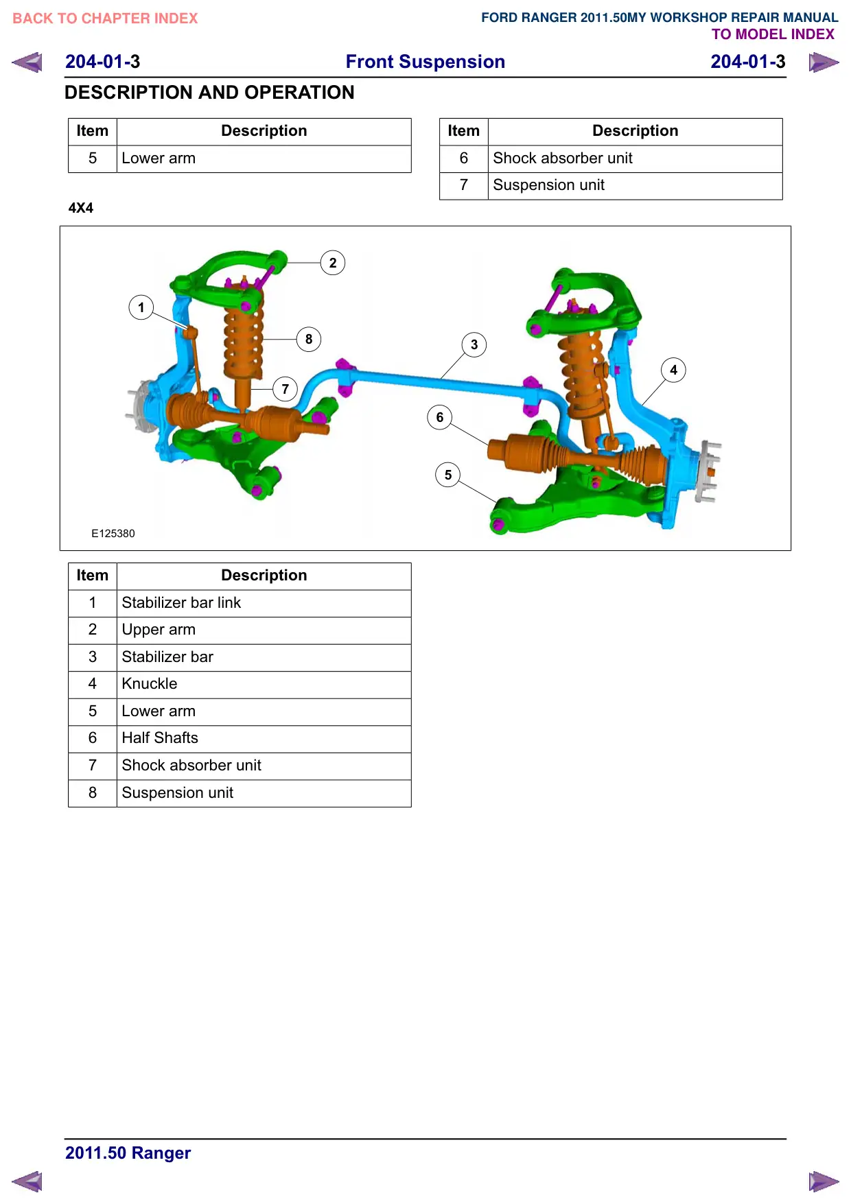
4X4
2
1
8
7
E125380
Item
Description
1
Stabilizer bar link
2
Upper arm
3
Stabilizer bar
4
Knuckle
5
Lower arm
6
Half Shafts
7
Shock absorber unit
8
Suspension unit
Item
Description
6
Shock absorber unit
7
Suspension unit
3
4
6
5
Front Suspension
204-01-5
204-01-5
REMOVAL AND INSTALLATION
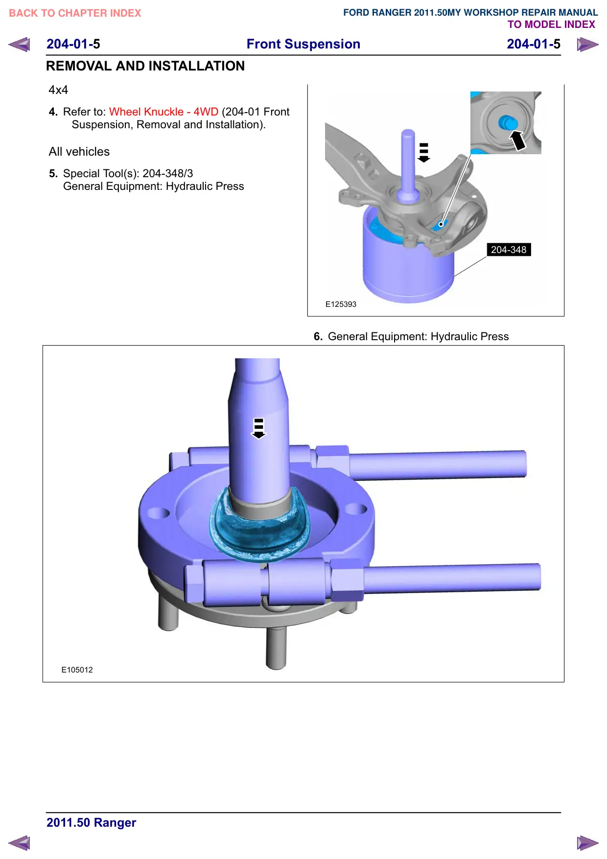
4x4
4. Refer to: Wheel Knuckle - 4WD (204-01 Front
Suspension, Removal and Installation).
All vehicles
5. Special Tool(s): 204-348/3
General Equipment: Hydraulic Press
E105012
204-348
E125393
6. General Equipment: Hydraulic Press
Front Suspension
204-01-6
204-01-6
REMOVAL AND INSTALLATION
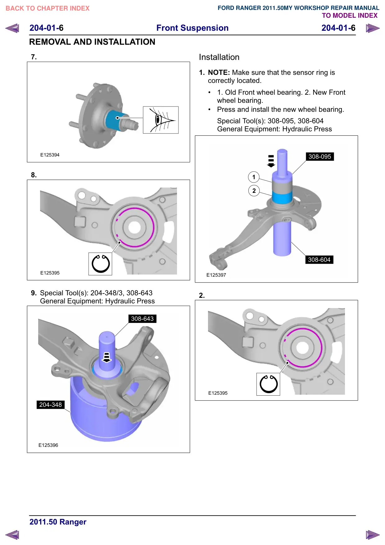
7.
E125394
8.
E125395
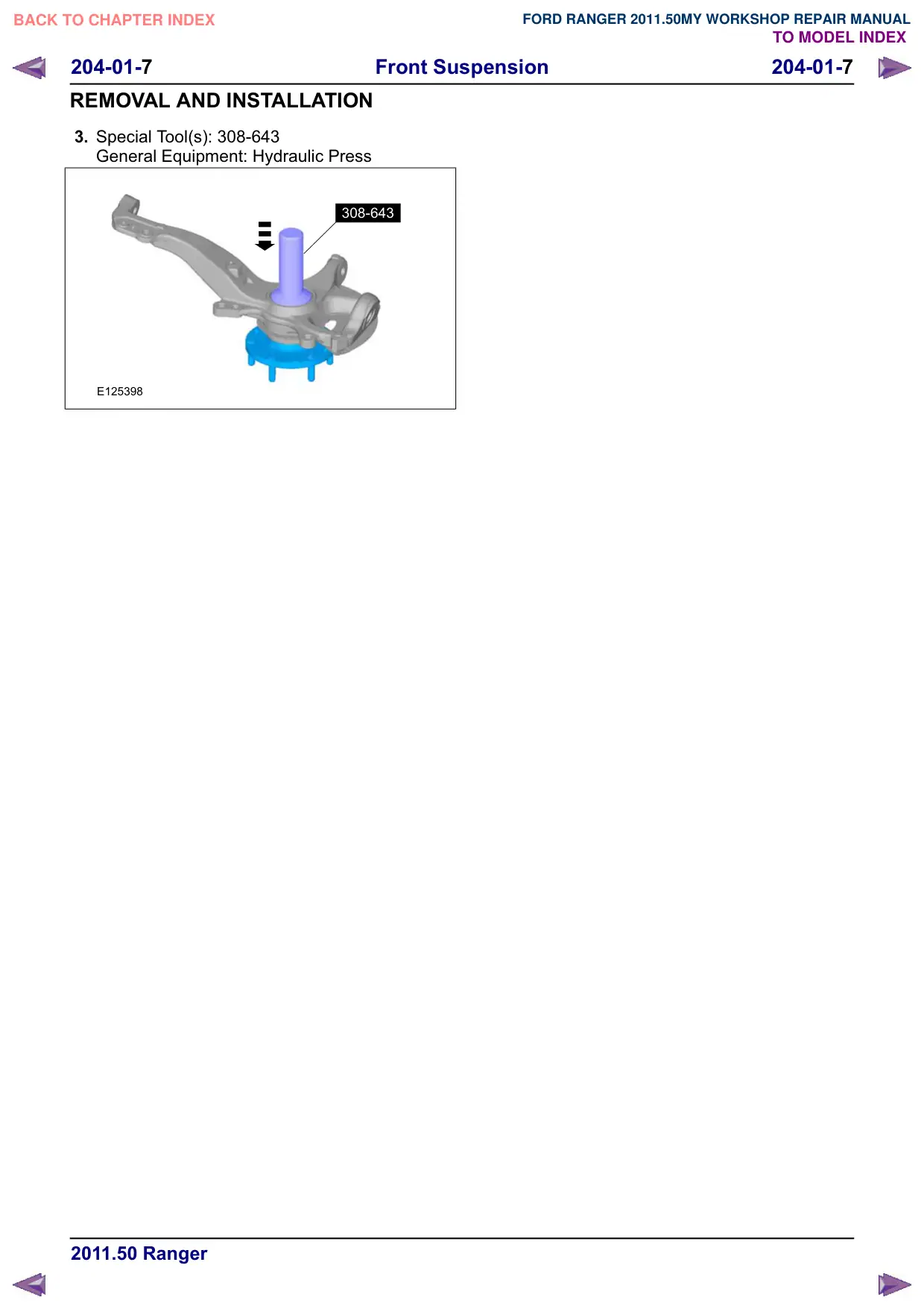
9. Special Tool(s): 204-348/3, 308-643
General Equipment: Hydraulic Press
308-643
204-348
E125396
Installation
1. NOTE: Make sure that the sensor ring is
correctly located.
1. Old Front wheel bearing. 2. New Front
wheel bearing.
Press and install the new wheel bearing.
Special Tool(s): 308-095, 308-604
General Equipment: Hydraulic Press
308-095
1
2
308-604
E125397
2.
E125395
Front Suspension
204-01-8
204-01-8
REMOVAL AND INSTALLATION
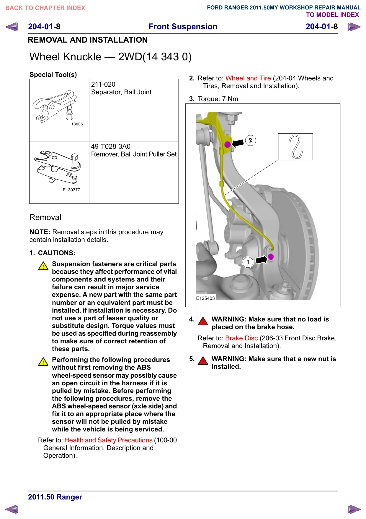
Wheel Knuckle – 2WD(14 343 0)
Special Tool(s)
211-020
Separator, Ball Joint
13005
49-T028-3A0
Remover, Ball Joint Puller Set
E139377
Removal
NOTE: Removal steps in this procedure may
contain installation details.
1. CAUTIONS:
Suspension fasteners are critical parts
because they affect performance of vital
components and systems and their
failure can result in major service
expense. A new part with the same part
number or an equivalent part must be
installed, if installation is necessary. Do
not use a part of lesser quality or
substitute design. Torque values must
be used as specified during reassembly
to make sure of correct retention of
these parts.
Performing the following procedures
without first removing the ABS
wheel-speed sensor may possibly cause
an open circuit in the harness if it is
pulled by mistake. Before performing
the following procedures, remove the
ABS wheel-speed sensor (axle side) and
fix it to an appropriate place where the
sensor will not be pulled by mistake
while the vehicle is being serviced.
Refer to: Health and Safety Precautions (100-00
General Information, Description and
Operation).
2. Refer to: Wheel and Tire (204-04 Wheels and
Tires, Removal and Installation).
3. Torque: 7 Nm
2
1
E125403
4.
WARNING: Make sure that no load is
placed on the brake hose.
Refer to: Brake Disc (206-03 Front Disc Brake,
Removal and Installation).
5.
WARNING: Make sure that a new nut is
installed.
Front Suspension
204-01-
204-01-
REMOVAL AND INSTALLATION
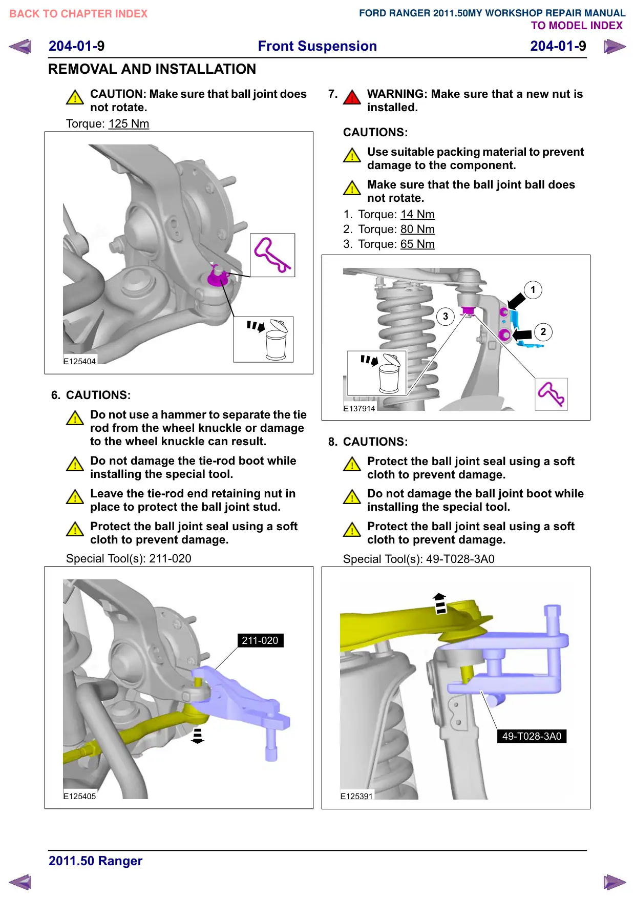
CAUTION: Make sure that ball joint does
not rotate.
Torque: 125 Nm
E125404
6. CAUTIONS:
Do not use a hammer to separate the tie
rod from the wheel knuckle or damage
to the wheel knuckle can result.
Do not damage the tie-rod boot while
installing the special tool.
Leave the tie-rod end retaining nut in
place to protect the ball joint stud.
Protect the ball joint seal using a soft
cloth to prevent damage.
Special Tool(s): 211-020
211-020
E125405
7.
WARNING: Make sure that a new nut is
installed.
CAUTIONS:
Use suitable packing material to prevent
damage to the component.
Make sure that the ball joint ball does
not rotate.
1. Torque: 14 Nm
2. Torque: 80 Nm
3. Torque: 65 Nm
1
3
2
E137914
8. CAUTIONS:
Protect the ball joint seal using a soft
cloth to prevent damage.
Do not damage the ball joint boot while
installing the special tool.
Protect the ball joint seal using a soft
cloth to prevent damage.
Special Tool(s): 49-T028-3A0
49-T028-3A0
E125391
Front Suspension
204-01-10
204-01-10
REMOVAL AND INSTALLATION
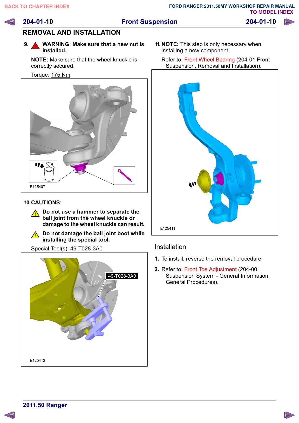
9.
WARNING: Make sure that a new nut is
installed.
NOTE: Make sure that the wheel knuckle is
correctly secured.
Torque: 175 Nm
E125407
10.CAUTIONS:
Do not use a hammer to separate the
ball joint from the wheel knuckle or
damage to the wheel knuckle can result.
Do not damage the ball joint boot while
installing the special tool.
Special Tool(s): 49-T028-3A0
49-T028-3A0
E125412
11. NOTE: This step is only necessary when
installing a new component.
Refer to: Front Wheel Bearing (204-01 Front
Suspension, Removal and Installation).
E125411
Installation
1. To install, reverse the removal procedure.
2. Refer to: Front Toe Adjustment (204-00
Suspension System - General Information,
General Procedures).
Front Suspension
204-01-11
204-01-11
REMOVAL AND INSTALLATION
Wheel Knuckle – 4WD(14 343 0)
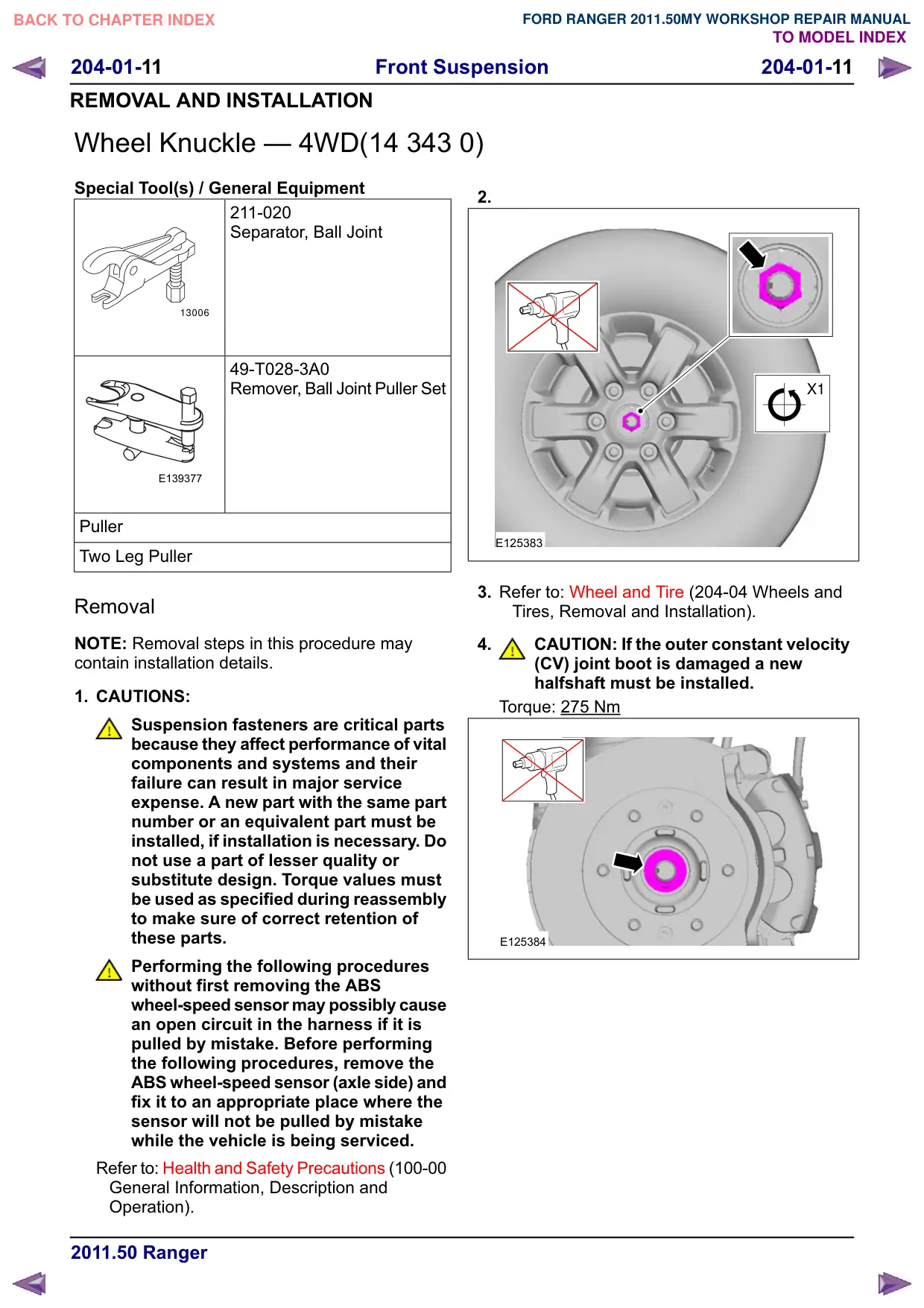
Special Tool(s) / General Equipment
211-020
Separator, Ball Joint
13006
49-T028-3A0
Remover, Ball Joint Puller Set
E139377
Puller
Two Leg Puller
Removal
NOTE: Removal steps in this procedure may
contain installation details.
1. CAUTIONS:
Suspension fasteners are critical parts
because they affect performance of vital
components and systems and their
failure can result in major service
expense. A new part with the same part
number or an equivalent part must be
installed, if installation is necessary. Do
not use a part of lesser quality or
substitute design. Torque values must
be used as specified during reassembly
to make sure of correct retention of
these parts.
Performing the following procedures
without first removing the ABS
wheel-speed sensor may possibly cause
an open circuit in the harness if it is
pulled by mistake. Before performing
the following procedures, remove the
ABS wheel-speed sensor (axle side) and
fix it to an appropriate place where the
sensor will not be pulled by mistake
while the vehicle is being serviced.
Refer to: Health and Safety Precautions (100-00
General Information, Description and
Operation).
2.
uN
E125383
3. Refer to: Wheel and Tire (204-04 Wheels and
Tires, Removal and Installation).
4.
CAUTION: If the outer constant velocity
(CV) joint boot is damaged a new
halfshaft must be installed.
Torque: 275 Nm
E125384
Front Suspension
204-01-12
204-01-12
REMOVAL AND INSTALLATION
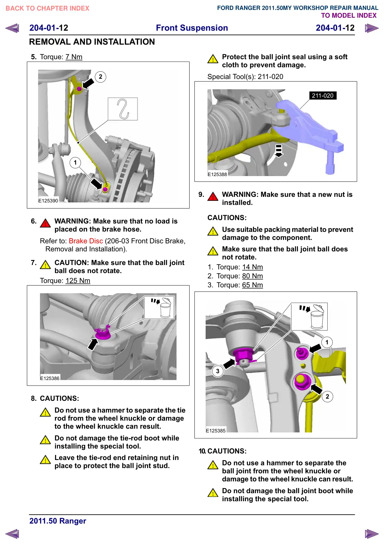
5. Torque: 7 Nm
2
1
E125390
6.
WARNING: Make sure that no load is
placed on the brake hose.
Refer to: Brake Disc (206-03 Front Disc Brake,
Removal and Installation).
7.
CAUTION: Make sure that the ball joint
ball does not rotate.
Torque: 125 Nm
E125386
8. CAUTIONS:
Do not use a hammer to separate the tie
rod from the wheel knuckle or damage
to the wheel knuckle can result.
Do not damage the tie-rod boot while
installing the special tool.
Leave the tie-rod end retaining nut in
place to protect the ball joint stud.
Protect the ball joint seal using a soft
cloth to prevent damage.
Special Tool(s): 211-020
211-020
E125388
9.
WARNING: Make sure that a new nut is
installed.
CAUTIONS:
Use suitable packing material to prevent
damage to the component.
Make sure that the ball joint ball does
not rotate.
1. Torque: 14 Nm
2. Torque: 80 Nm
3. Torque: 65 Nm
1
3
2
E125385
10.CAUTIONS:
Do not use a hammer to separate the
ball joint from the wheel knuckle or
damage to the wheel knuckle can result.
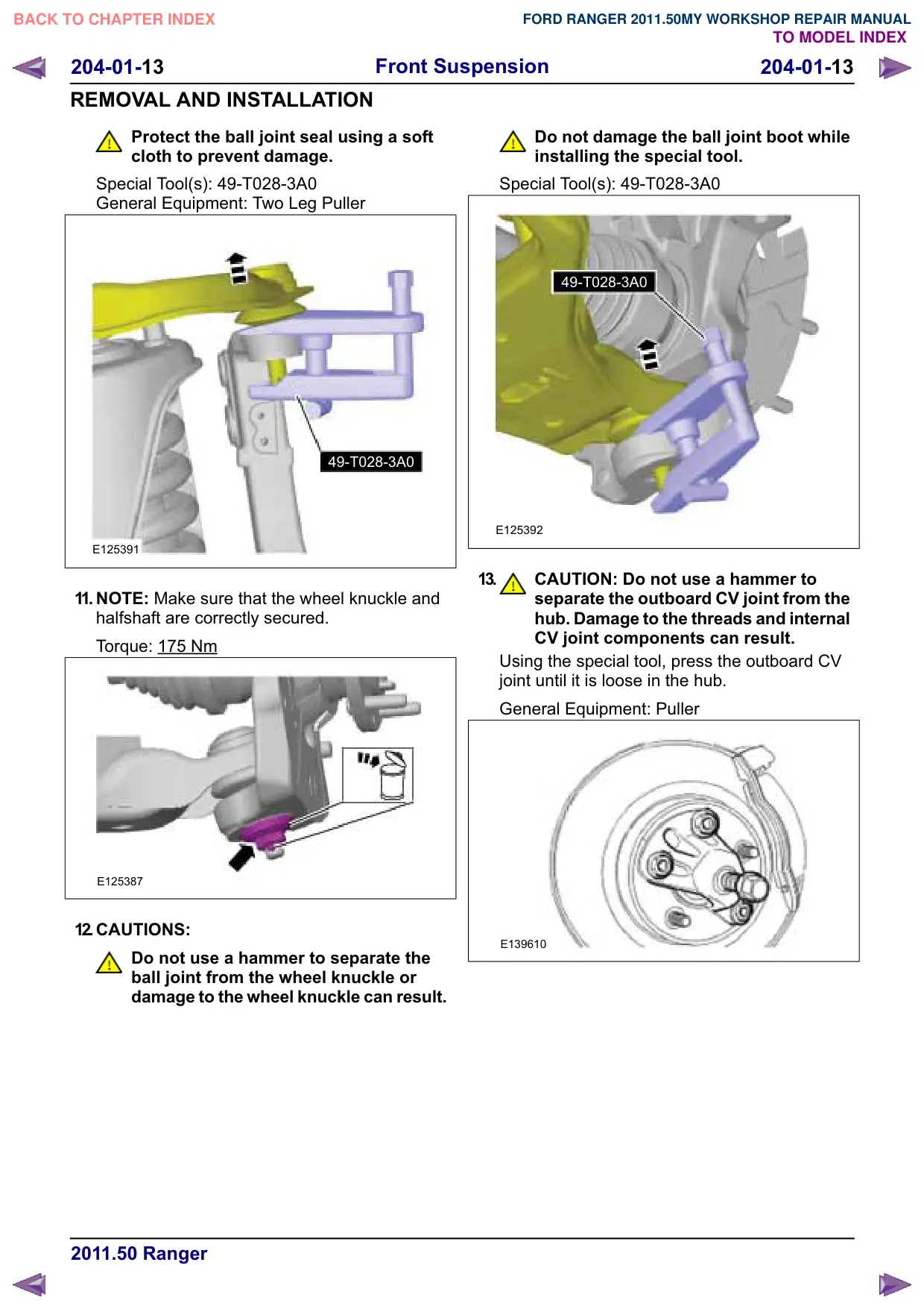
Do not damage the ball joint boot while
installing the special tool.
204-01-13
Front Suspension
204-01-13
REMOVAL AND INSTALLATION
Protect the ball joint seal using a soft
cloth to prevent damage.
Special Tool(s): 49-T028-3A0
General Equipment: Two Leg Puller
49-T028-3A0
E125391
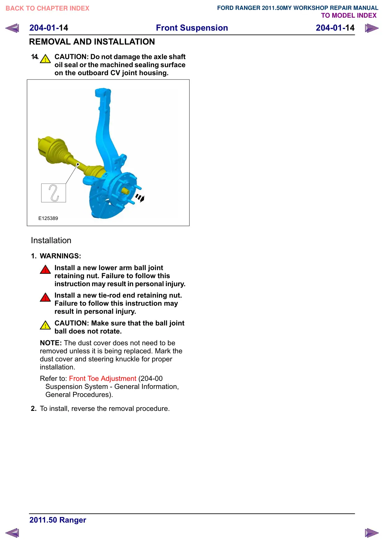
11. NOTE: Make sure that the wheel knuckle and
halfshaft are correctly secured.
Torque: 175 Nm
E125387
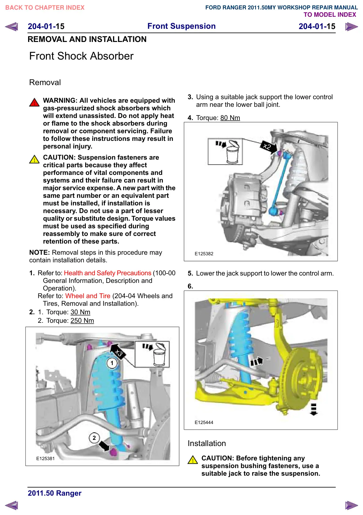
12.CAUTIONS:
Do not use a hammer to separate the
ball joint from the wheel knuckle or
damage to the wheel knuckle can result.
Do not damage the ball joint boot while
installing the special tool.
Special Tool(s): 49-T028-3A0
49-T028-3A0
E125392
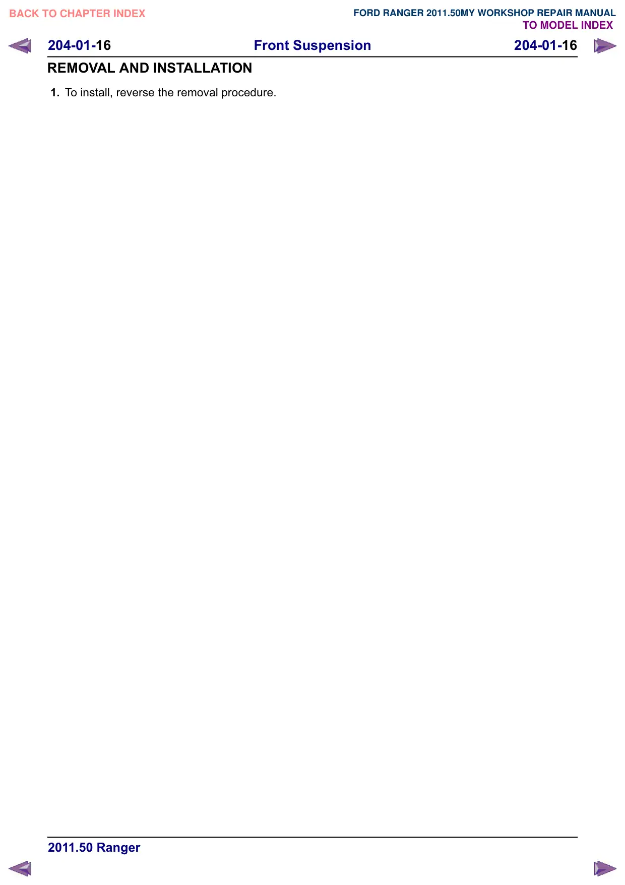
13.
CAUTION: Do not use a hammer to
separate the outboard CV joint from the
hub. Damage to the threads and internal
CV joint components can result.
Using the special tool, press the outboard CV
joint until it is loose in the hub.
General Equipment: Puller
E139610
Front Suspension
204-01-14
204-01-14
REMOVAL AND INSTALLATION
14.
CAUTION: Do not damage the axle shaft
oil seal or the machined sealing surface
on the outboard CV joint housing.
E125389
Installation
1. WARNINGS:
Install a new lower arm ball joint
retaining nut. Failure to follow this
instruction may result in personal injury.
Install a new tie-rod end retaining nut.
Failure to follow this instruction may
result in personal injury.
CAUTION: Make sure that the ball joint
ball does not rotate.
NOTE: The dust cover does not need to be
removed unless it is being replaced. Mark the
dust cover and steering knuckle for proper
installation.
Refer to: Front Toe Adjustment (204-00
Suspension System - General Information,
General Procedures).
2. To install, reverse the removal procedure.
204-01-15
Front Suspension
204-01-15
REMOVAL AND INSTALLATION
Front Shock Absorber
Removal
WARNING: All vehicles are equipped with
gas-pressurized shock absorbers which
will extend unassisted. Do not apply heat
or flame to the shock absorbers during
removal or component servicing. Failure
to follow these instructions may result in
personal injury.
CAUTION: Suspension fasteners are
critical parts because they affect
performance of vital components and
systems and their failure can result in
major service expense. A new part with the
same part number or an equivalent part
must be installed, if installation is
necessary. Do not use a part of lesser
quality or substitute design. Torque values
must be used as specified during
reassembly to make sure of correct
retention of these parts.
NOTE: Removal steps in this procedure may
contain installation details.
1. Refer to: Health and Safety Precautions (100-00
General Information, Description and
Operation).
Refer to: Wheel and Tire (204-04 Wheels and
Tires, Removal and Installation).
2.
1.
Torque: 30
Nm
2. Torque: 250 Nm
x3
1
2
E125381
3. Using a suitable jack support the lower control
arm near the lower ball joint.
4. Torque: 80
Nm
x2
E125382
5. Lower the jack support to lower the control arm.
6.
E125444
Installation
CAUTION: Before tightening any
suspension bushing fasteners, use a
suitable jack to raise the suspension.
Front Suspension
204-01-17
204-01-17
REMOVAL AND INSTALLATION
Lower Arm(14 706 0; 14 707 0; 14 709 0)
General Equipment
Two Leg Puller
Removal
CAUTION: Suspension fasteners are
critical parts because they affect
performance of vital components and
systems and their failure can result in
major service expense. A new part with the
same part number or an equivalent part
must be installed, if installation is
necessary. Do not use a part of lesser
quality or substitute design. Torque values
must be used as specified during
reassembly to make sure of correct
retention of these parts.
NOTE: Removal steps in this procedure may
contain installation details.
1. Refer to: Health and Safety Precautions (100-00
General Information, Description and
Operation).
Refer to: Wheel and Tire (204-04 Wheels and
Tires, Removal and Installation).
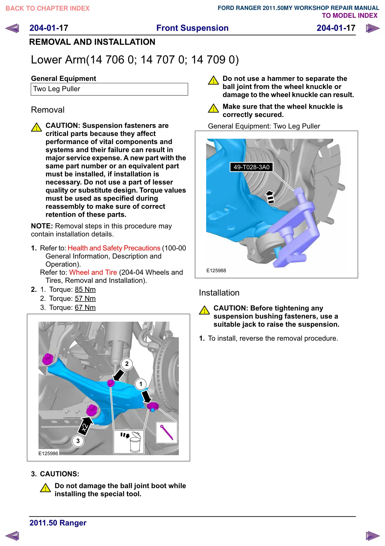
2.
1.
Torque: 85 Nm
2. Torque: 57 Nm
3. Torque: 67 Nm
2
1
x2
3
E125986
3. CAUTIONS:
Do not damage the ball joint boot while
installing the special tool.
Do not use a hammer to separate the
ball joint from the wheel knuckle or
damage to the wheel knuckle can result.
Make sure that the wheel knuckle is
correctly secured.
General Equipment: Two Leg Puller
49-T028-3A0
E125988
Installation
CAUTION: Before tightening any
suspension bushing fasteners, use a
suitable jack to raise the suspension.
1. To install, reverse the removal procedure.
Front Suspension
204-01-18
204-01-18
REMOVAL AND INSTALLATION
Upper Arm
Special Tool(s) / General Equipment
204-288A
Remover/Installer, Ball Joint
E115081
Removal
CAUTION: Suspension fasteners are
critical parts because they affect
performance of vital components and
systems and their failure can result in
major service expense. A new part with the
same part number or an equivalent part
must be installed, if installation is
necessary. Do not use a part of lesser
quality or substitute design. Torque values
must be used as specified during
reassembly to make sure of correct
retention of these parts.
NOTE: Removal steps in this procedure may
contain installation details.
Special Tool(s) / General Equipment
Two Leg Puller
1. Refer to: Health and Safety Precautions (100-00
General Information, Description and
Operation).
Refer to: Wheel and Tire (204-04 Wheels and
Tires, Removal and Installation).
2. Refer to: Front Wheel Speed Sensor (206-09
Anti-Lock Control, Removal and Installation).
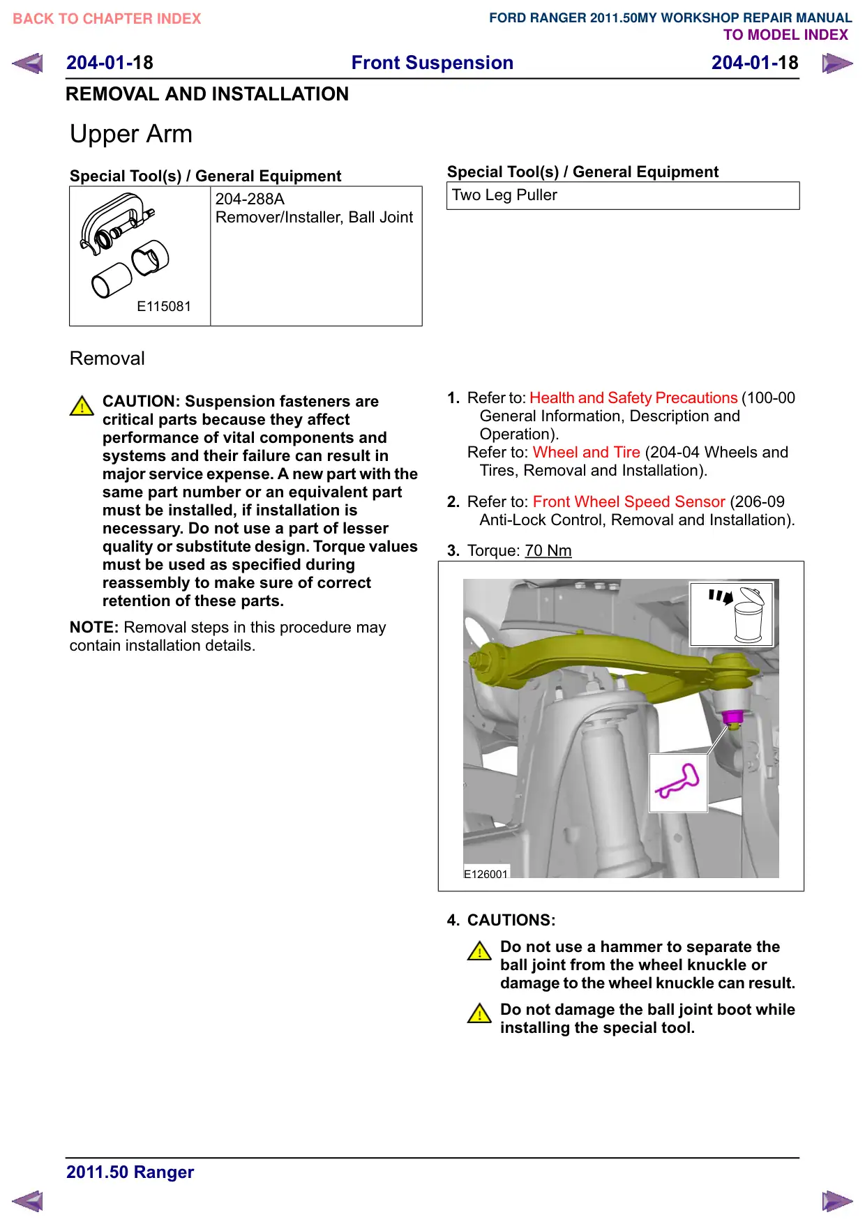
3. Torque: 70 Nm
E126001
4. CAUTIONS:
Do not use a hammer to separate the
ball joint from the wheel knuckle or
damage to the wheel knuckle can result.
Do not damage the ball joint boot while
installing the special tool.
Front Suspension
204-01-19
204-01-19
REMOVAL AND INSTALLATION
Make sure that the knuckle assembly is
secured secured with suitable retaining
straps.
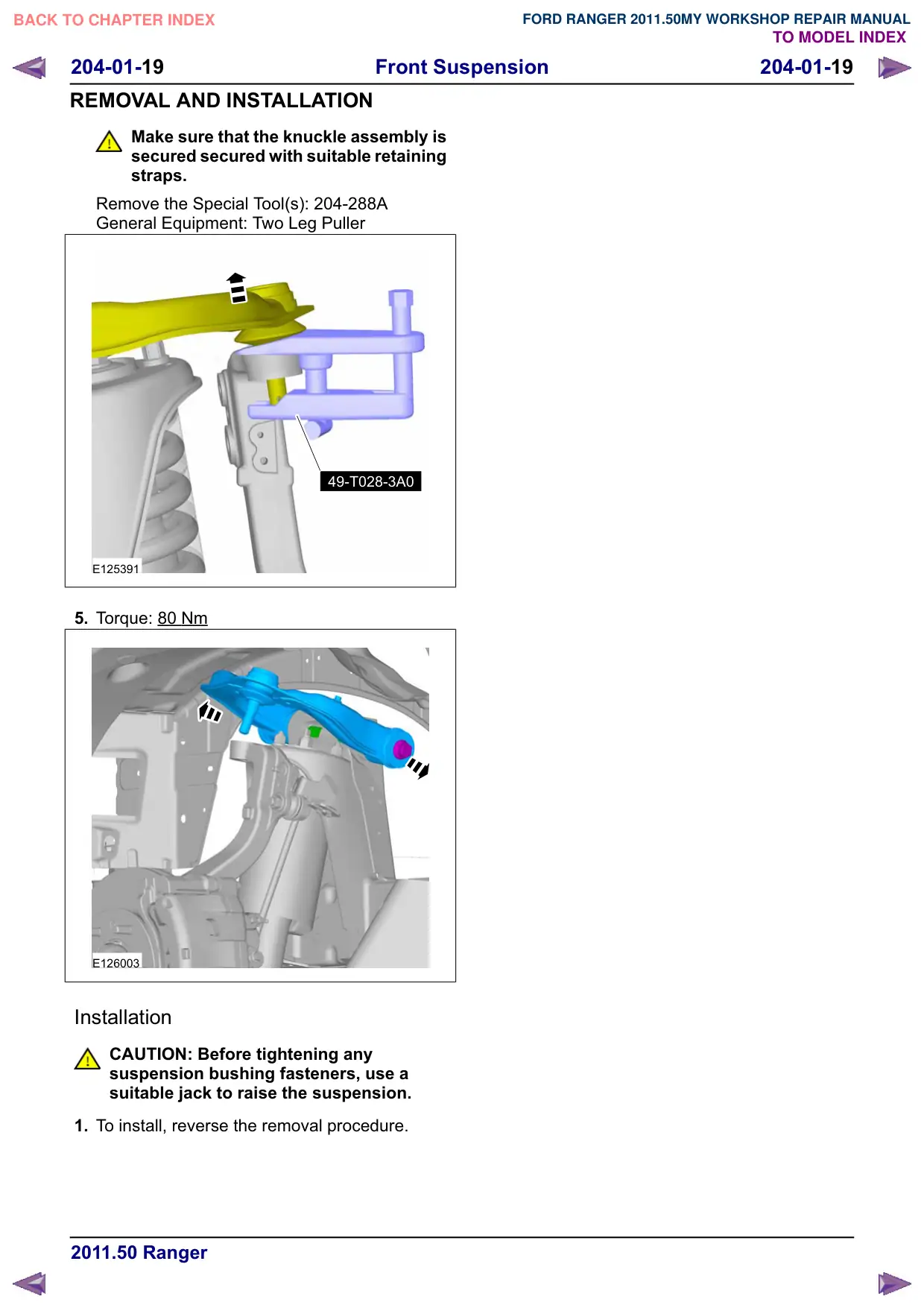
Remove the Special Tool(s): 204-288A
General Equipment: Two Leg Puller
49-T028-3A0
E125391
5. Torque: 80 Nm
E126003
Installation
CAUTION: Before tightening any
suspension bushing fasteners, use a
suitable jack to raise the suspension.
1. To install, reverse the removal procedure.