Engine Cooling
303-03C-2
303-03C-2
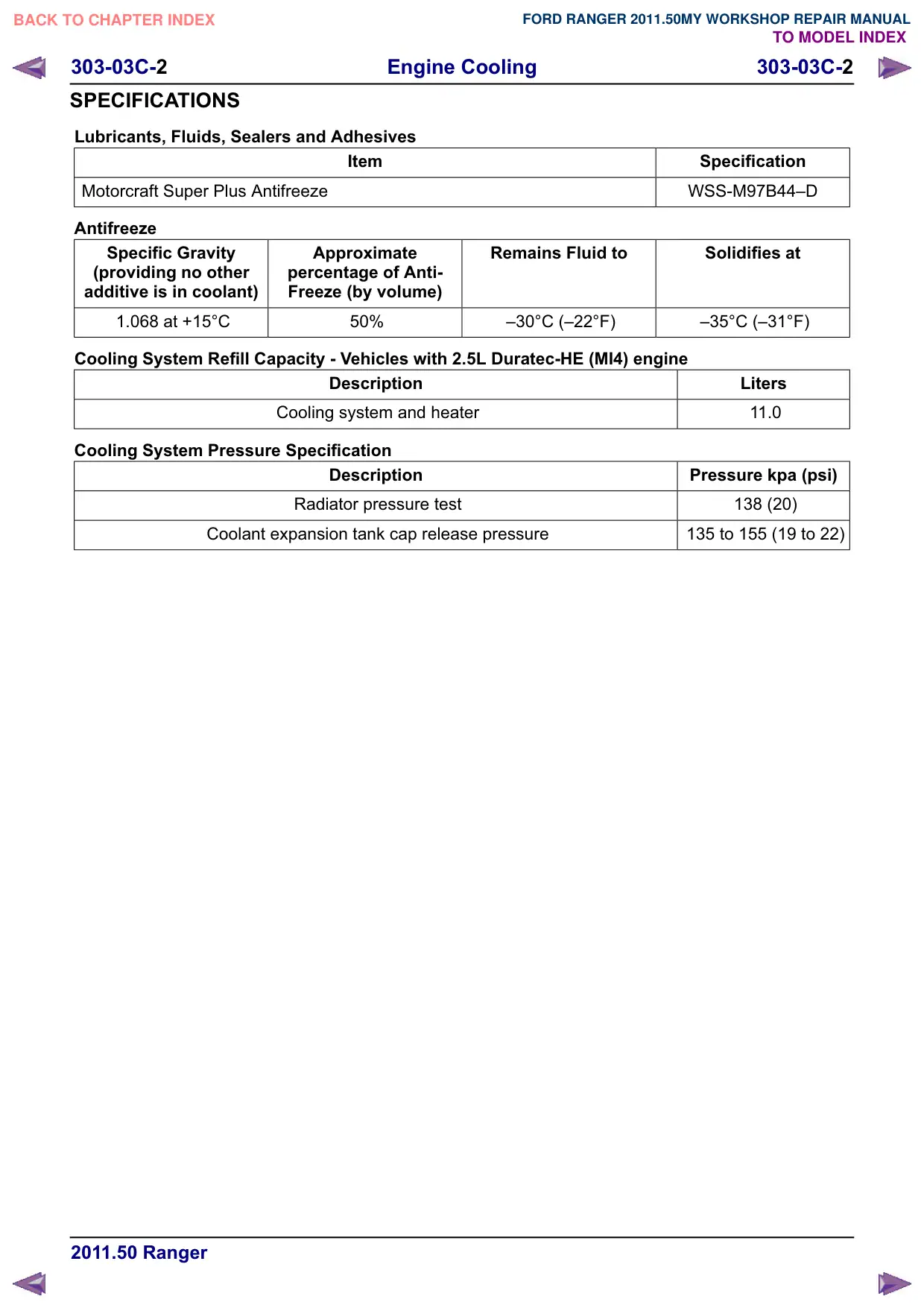
SPECIFICATIONS
Lubricants, Fluids, Sealers and Adhesives
Item
Motorcraft Super Plus Antifreeze
Antifreeze
Specific Gravity
Approximate
(providing no other
percentage of Anti-
additive is in coolant)
Freeze (by volume)
1.068 at +15°C
50%
Cooling System Refill Capacity - Vehicles with 2.5L Duratec-HE (MI4) engine
Description
Cooling system and heater
Cooling System Pressure Specification
Description
Radiator pressure test
Coolant expansion tank cap release pressure
Specification
WSS-M97B44œD
Remains Fluid to
Solidifies at
œ30°C (œ22°F)
œ35°C (œ31°F)
Liters
11.0
Pressure kpa (psi)
138 (20)
135 to 155 (19 to 22)
Engine Cooling
303-03C-3
303-03C-3
DESCRIPTION AND OPERATION
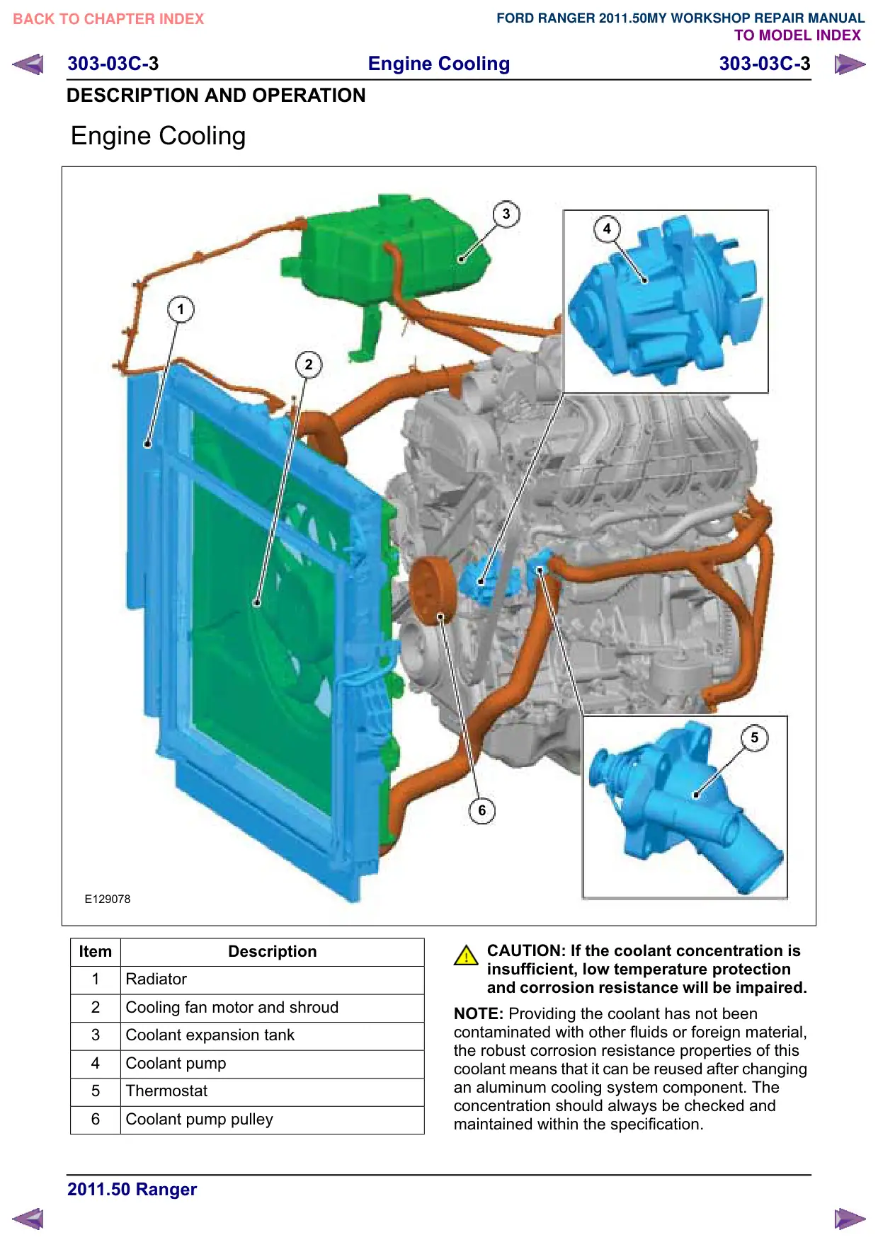
Engine Cooling
1
2
E129078
Item
Description
1
Radiator
2
Cooling fan motor and shroud
3
Coolant expansion tank
4
Coolant pump
5
Thermostat
6
Coolant pump pulley
3
4
5
6
CAUTION: If the coolant concentration is
insufficient, low temperature protection
and corrosion resistance will be impaired.
NOTE: Providing the coolant has not been
contaminated with other fluids or foreign material,
the robust corrosion resistance properties of this
coolant means that it can be reused after changing
an aluminum cooling system component. The
concentration should always be checked and
maintained within the specification.
Engine Cooling
303-03C-4
303-03C-4
DESCRIPTION AND OPERATION
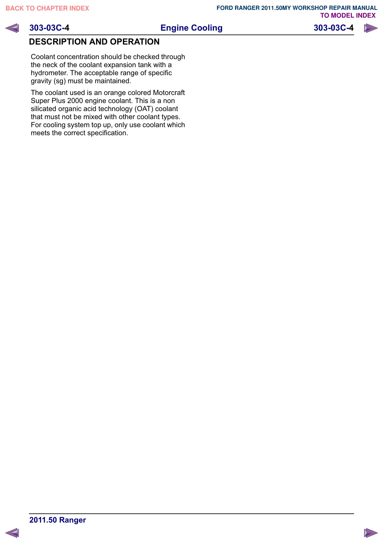
Coolant concentration should be checked through
the neck of the coolant expansion tank with a
hydrometer. The acceptable range of specific
gravity (sg) must be maintained.
The coolant used is an orange colored Motorcraft
Super Plus 2000 engine coolant. This is a non
silicated organic acid technology (OAT) coolant
that must not be mixed with other coolant types.
For cooling system top up, only use coolant which
meets the correct specification.
Engine Cooling
303-03C-5
303-03C-5
GENERAL PROCEDURES
Cooling System Draining, Filling and Bleeding(24 122 0)
Draining
WARNING: When releasing the cooling
system pressure, cover the coolant
expansion tank cap with a thick cloth.
1. Release the cooling system pressure by slowly
turning the coolant expansion tank cap between
2 and 3 turns.
x3
E139585
2.
E139584
3. Refer to: Lifting (100-02 Jacking and Lifting,
Description and Operation).
4.
x4
E130132
5. Remove the radiator drain plug and drain the
coolant.
E139586
6. Install the radiator drain plug.
7. Lower the vehicle.
Filling
1. Refill the coolant to the expansion tank to
maximum line (+15mm).
Bleeding
CAUTION: The fluid level must remain
between the MAX and MIN marks.
1. Run the engine for 5 minutes at idle rpm.
2. Install the coolant expansion tank cap.
3. Run the engine speed to 2500 RPM and
maintain it for approximately 15 minutes.
4. Run the engine for 5minutes at idle rpm.
5. Switch the engine off.
6. Check the cooling system for leaks.
Engine Cooling
303-03C-6
303-03C-6
GENERAL PROCEDURES
7. Refer to: Lifting (100-02 Jacking and Lifting,
Description and Operation).
8. Torque: 30 Nm
x4
E130132
9. Lower the vehicle.
10.Allow the engine to cool and maintain close to
room temperature.
11. Fill the coolant to the expansion tank max fill
line, if required.
Engine Cooling
303-03C-7
303-03C-7
GENERAL PROCEDURES
Cooling System Draining and Vacuum Filling
General Equipment
Cooling System Vacuum Tester and Refiller
Fluid Container
Draining
WARNING: When releasing the cooling
system pressure, cover the coolant
expansion tank cap with a thick cloth.
NOTE: Always follow the manufacturer's
instructions when handling the equipment.
1. Refer to: Engine Cooling System Health and
Safety Precautions (100-00 General
Information, Description and Operation).
2.
Release the cooling system pressure by slowly
turning the coolant expansion tank cap between
2 and 3 turns.
x3
E139585
3. Refer to: Lifting (100-02 Jacking and Lifting,
Description and Operation).
4.
x4
E130132
5.
WARNING: Be prepared to collect
escaping fluid.
Use a suitable coolant hose to drain the coolant.
General Equipment: Fluid Container
Loosen: 4 turn(s)
E139674
6. Install the radiator drain plug.
E139670
7. Torque: 30 Nm
x4
E130132
Engine Cooling
303-03C-8
303-03C-8
GENERAL PROCEDURES
Evacuating and Filling
1.
If the cooling system was completely drained,
fill the fluid container with the full cooling
system fill capacity plus 0.5L of additional
coolant.
If the cooling system was partially drained,
fill the fluid container with the removed and
spilled amount of coolant plus 1.0L of
additional coolant. When in doubt always use
the full cooling system fill capacity plus 0.5L
of additional coolant.
2. Remove the coolant expansion tank cap.
E139584
3.
1.
Close the valve, install the coolant hose and
place it into the fluid container.
General Equipment: Cooling System Vacuum
Tester and Refiller
2. Close the valve and connect the compressed
air hose.
1
2
E139671
4.
1.
General Equipment: Cooling System Vacuum
Tester and Refiller
2. Open the valve until the specificied vacuum
is achieved.
-0 .. 8 5 b a r
2
-0. 9 5 b a r
1
6-10bar
E139672
5.
Open the valve until the coolant reservoir
fluid level is at the MAX mark.
General Equipment: Cooling System Vacuum
Tester and Refiller
If no coolant is visible in the coolant
expansion tank, add 2.0L of coolant to the
fluid container and repeat the evacuating and
filling procedure.
E139673
6. Install the coolant expansion tank cap.
E139675
Engine Cooling
303-03C-
303-03C-
REMOVAL AND INSTALLATION
Thermostat(24 454 0)
Removal
NOTE: Removal steps in this procedure may
contain installation details.
1. Drain the cooling system.
Refer to: Cooling System Draining, Filling and
Bleeding (303-03 Engine Cooling, General
Procedures).
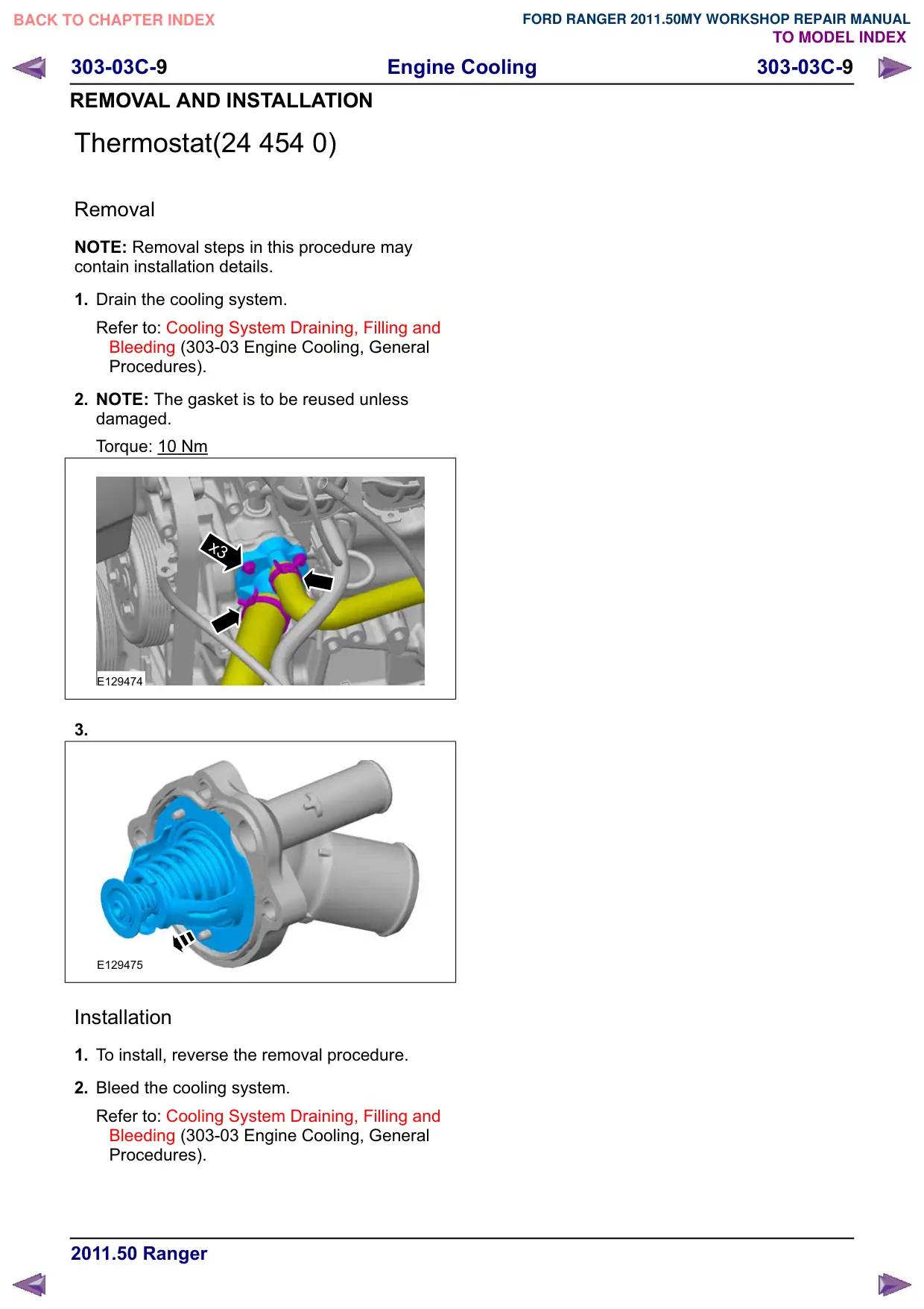
2. NOTE: The gasket is to be reused unless
damaged.
Torque: 10 Nm
x3
E129474
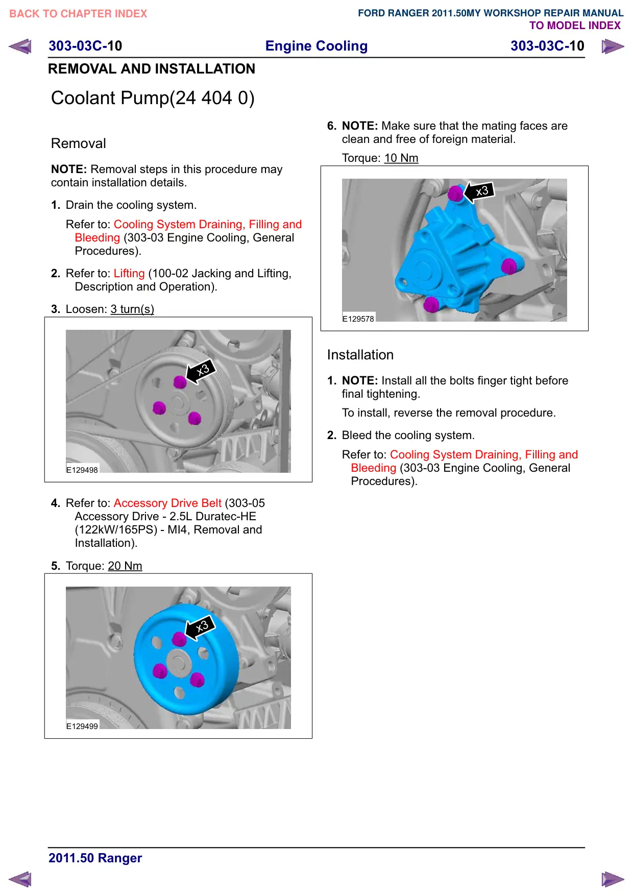
3.
E129475
Installation
1. To install, reverse the removal procedure.
2. Bleed the cooling system.
Refer to: Cooling System Draining, Filling and
Bleeding (303-03 Engine Cooling, General
Procedures).
Engine Cooling
303-03C-10
303-03C-10
REMOVAL AND INSTALLATION
Coolant Pump(24 404 0)
Removal
NOTE: Removal steps in this procedure may
contain installation details.
1. Drain the cooling system.
Refer to: Cooling System Draining, Filling and
Bleeding (303-03 Engine Cooling, General
Procedures).
2. Refer to: Lifting (100-02 Jacking and Lifting,
Description and Operation).
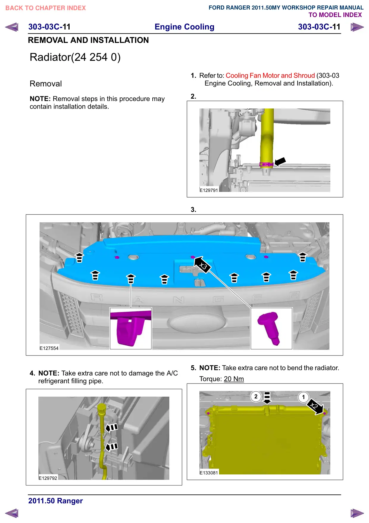
3. Loosen: 3 turn(s)
x3
E129498
4. Refer to: Accessory Drive Belt (303-05
Accessory Drive - 2.5L Duratec-HE
(122kW/165PS) - MI4, Removal and
Installation).
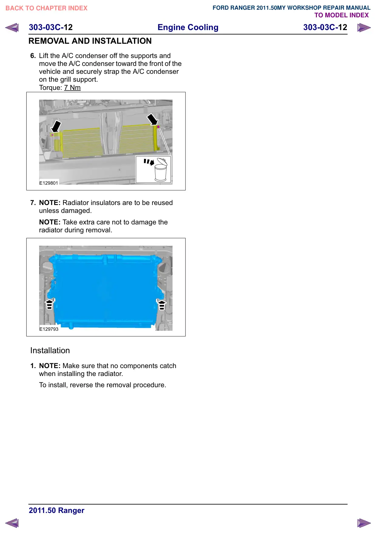
5. Torque: 20 Nm
x3
E129499
6. NOTE: Make sure that the mating faces are
clean and free of foreign material.
Torque: 10 Nm
x3
E129578
Installation
1. NOTE: Install all the bolts finger tight before
final tightening.
To install, reverse the removal procedure.
2. Bleed the cooling system.
Refer to: Cooling System Draining, Filling and
Bleeding (303-03 Engine Cooling, General
Procedures).
Engine Cooling
303-03C-11
303-03C-11
REMOVAL AND INSTALLATION
Radiator(24 254 0)
Removal
NOTE: Removal steps in this procedure may
contain installation details.
E127554
4. NOTE: Take extra care not to damage the A/C
refrigerant filling pipe.
E129792
1. Refer to: Cooling Fan Motor and Shroud (303-03
Engine Cooling, Removal and Installation).
2.
E129791
3.
x3
5. NOTE: Take extra care not to bend the radiator.
Torque: 20 Nm
2
1
x2
E133081
Engine Cooling
303-03C-12
303-03C-12
REMOVAL AND INSTALLATION
6. Lift the A/C condenser off the supports and
move the A/C condenser toward the front of the
vehicle and securely strap the A/C condenser
on the grill support.
Torque: 7 Nm
E129801
7. NOTE: Radiator insulators are to be reused
unless damaged.
NOTE: Take extra care not to damage the
radiator during removal.
E129793
Installation
1. NOTE: Make sure that no components catch
when installing the radiator.
To install, reverse the removal procedure.
303-03C-13
Engine Cooling
303-03C-13
REMOVAL AND INSTALLATION
Cooling Fan Motor and Shroud(24 222 0)
Removal
NOTE: Removal steps in this procedure may
contain installation details.
1. Drain the cooling system.
Refer to: Cooling System Draining, Filling and
Bleeding (303-03 Engine Cooling, General
Procedures).
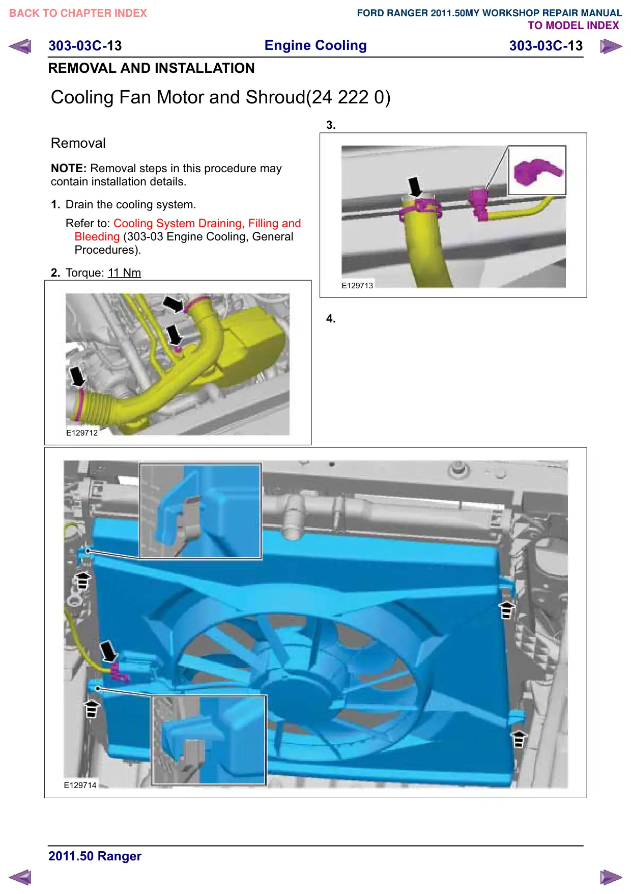
2. Torque: 1
1 Nm
E129712
E129714
3.
E129713
4.
Engine Cooling
303-03C-14
303-03C-14
REMOVAL AND INSTALLATION
Installation
1. To install, reverse the removal procedure.
2. Bleed the cooling system.
Refer to: Cooling System Draining, Filling and
Bleeding (303-03 Engine Cooling, General
Procedures).
Engine Cooling
303-03C-15
303-03C-15
REMOVAL AND INSTALLATION
Coolant Outlet Connector
Removal
NOTE: Removal steps in this procedure may
contain installation details.
1. Drain the cooling system.
Refer to: Cooling System Draining, Filling and
Bleeding (303-03 Engine Cooling, General
Procedures).
2. Refer to: Lifting (100-02 Jacking and Lifting,
Description and Operation).
3. Refer to: Cowl Panel Grille (501-02 Front End
Body Panels, Removal and Installation).
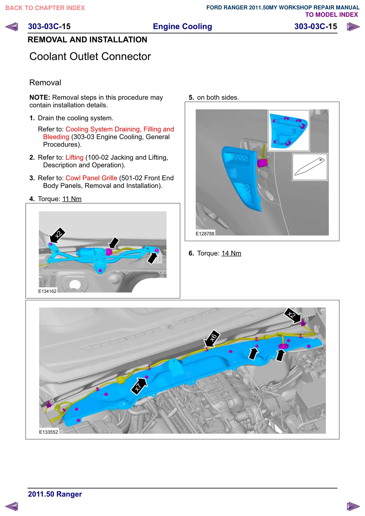
4. Torque: 11 Nm
x2
E134162
x7
E133552
5. on both sides.
E128788
6. Torque: 14 Nm
x2
x6
Engine Cooling
303-03C-16
303-03C-16
REMOVAL AND INSTALLATION
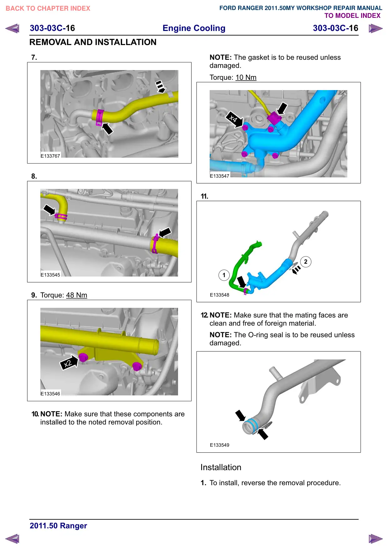
7.
E133767
8.
E133545
9. Torque: 48 Nm
x2
E133546
10.NOTE: Make sure that these components are
installed to the noted removal position.
NOTE: The gasket is to be reused unless
damaged.
Torque: 10 Nm
x4
E133547
11.
2
1
E133548
12.NOTE: Make sure that the mating faces are
clean and free of foreign material.
NOTE: The O-ring seal is to be reused unless
damaged.
E133549
Installation
1. To install, reverse the removal procedure.
Engine Cooling
303-03C-17
303-03C-17
REMOVAL AND INSTALLATION
2. Bleed the cooling system.
Refer to: Cooling System Draining, Filling and
Bleeding (303-03 Engine Cooling, General
Procedures).