Brake System - General Information
206-00-2
206-00-2
SPECIFICATIONS
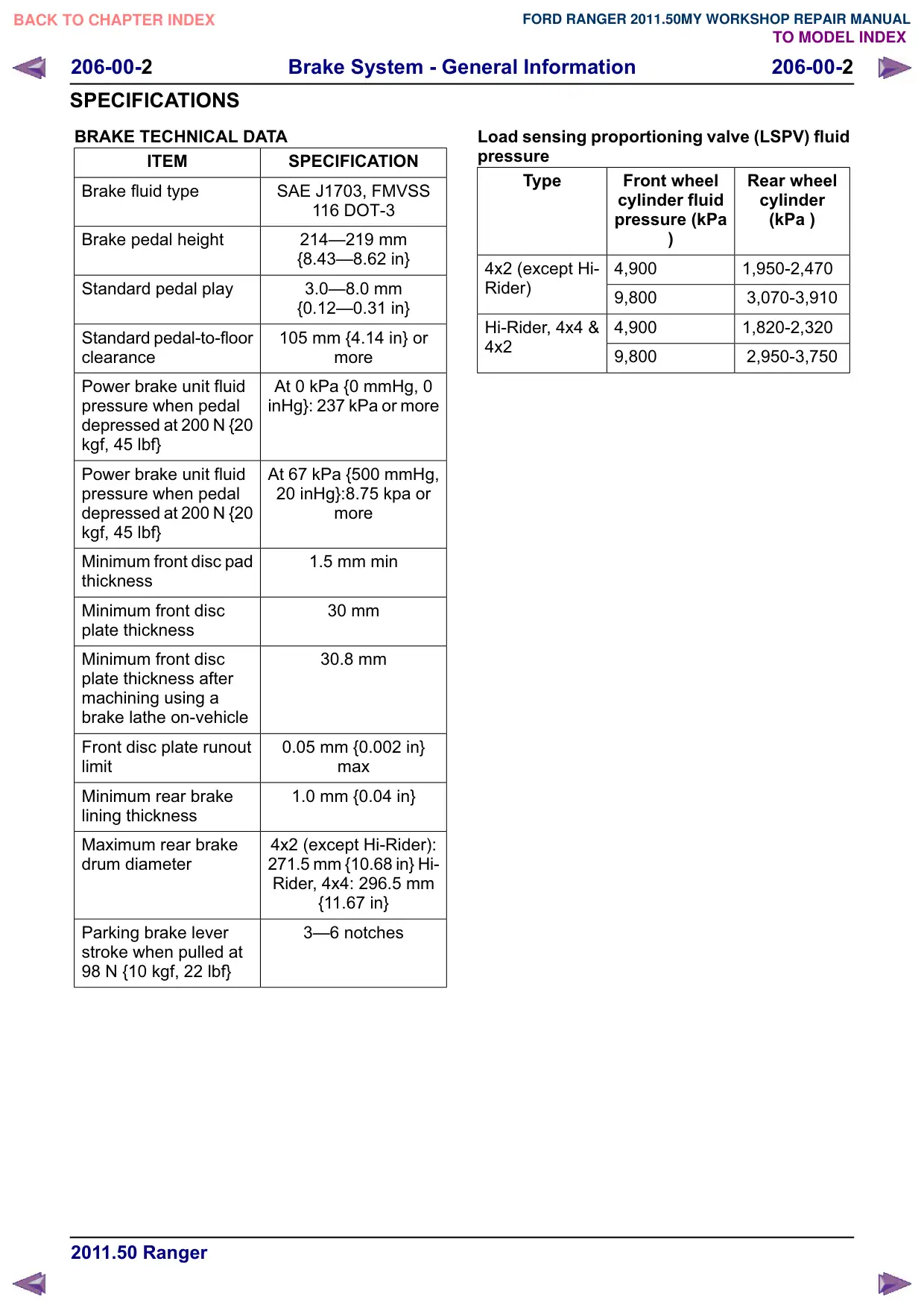
BRAKE TECHNICAL DATA
ITEM
SPECIFICATION
Brake fluid type
SAE J1703, FMVSS
116 DOT-3
Brake pedal height
214–219 mm
{8.43–8.62 in}
Standard pedal play
3.0–8.0 mm
{0.12–0.31 in}
Standard pedal-to-floor
105 mm {4.14 in} or
clearance
PRUH
Power brake unit fluid
At 0 kPa {0 mmHg, 0
pressure when pedal
inHg}: 237 kPa or more
depressed at 200 N {20
kgf, 45 lbf}
Power brake unit fluid
At 67 kPa {500 mmHg,
pressure when pedal
20 inHg}:8.75 kpa or
depressed at 200 N {20
PRUH
kgf, 45 lbf}
Minimum front disc pad
1.5 mm min
thickness
Minimum front disc
30 mm
plate thickness
Minimum front disc
30.8 mm
plate thickness after
machining using a
brake lathe on-vehicle
Front disc plate runout
0.05 mm {0.002 in}
limit
PD[
Minimum rear brake
1.0 mm {0.04 in}
lining thickness
Maximum rear brake
4x2 (except Hi-Rider):
drum diameter
271.5 mm {10.68 in} Hi-
Rider, 4x4: 296.5 mm
{11.67 in}
Parking brake lever
3–6 notches
stroke when pulled at
98 N {10 kgf, 22 lbf}
Load sensing proportioning valve (LSPV) fluid
pressure
Type
Front wheel
Rear wheel
cylinder fluid
cylinder
pressure (kPa
(kPa )
4x2 (except Hi-
4,900
1,950-2,470
Rider)
9,800
3,070-3,910
Hi-Rider, 4x4 &
4,900
1,820-2,320
4x2
9,800
2,950-3,750
Brake System - General Information
206-00-3
206-00-3
GENERAL PROCEDURES
Brake Load Sensor Proportioning Valve Adjustment(12 136 0)
1. Place the unloaded vehicle on level ground.
Unloaded: Fuel tank is full. Jack and tools
are in designated position.
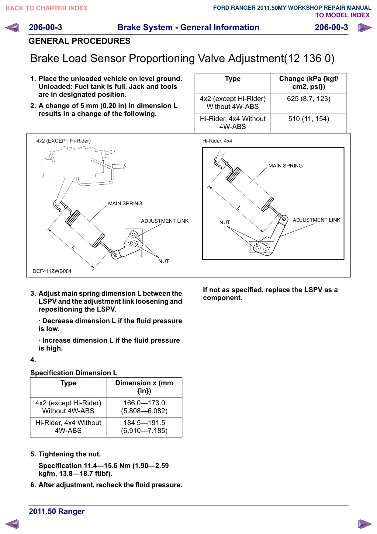
2. A change of 5 mm (0.20 in) in dimension L
results in a change of the following.
DCF411ZWB004
3. Adjust main spring dimension L between the
LSPV and the adjustment link loosening and
repositioning the LSPV.
‡ Decrease dimension L if the fluid pressure
is low.
‡ Increase dimension L if the fluid pressure
is high.
4.
Specification Dimension L
Type
Dimension x (mm
{in})
4x2 (except Hi-Rider)
166.0–173.0
Without 4W-ABS
(5.808–6.082)
Hi-Rider, 4x4 Without
184.5–191.5
4W-ABS
(6.910–7.185)
5. Tightening the nut.
Specification 11.4–15.6 Nm (1.90–2.59
kgfm, 13.8–18.7 ftlbf).
6. After adjustment, recheck the fluid pressure.
Type
Change (kPa {kgf/
cm2, psl})
4x2 (except Hi-Rider)
625 (8.7, 123)
Without 4W-ABS
Hi-Rider, 4x4 Without
510 (11, 154)
4W-ABS
If not as specified, replace the LSPV as a
component.
Brake System - General Information
206-00-4
206-00-4
GENERAL PROCEDURES
Front Brake Disc Runout Check
Special Tool(s) / General Equipment
205-044
Holding Fixture, Dial Indicator
Gauge
15008
205-069
Dial Indicator Gauge (Metric)
15046
205-070
Holding Fixture, Dial Indicator
Gauge
15022A
Calliper Gauge
Activation
1. Refer to: Wheel and Tire (204-04 Wheels and
Tires, Removal and Installation).
2.
2
1
E125507
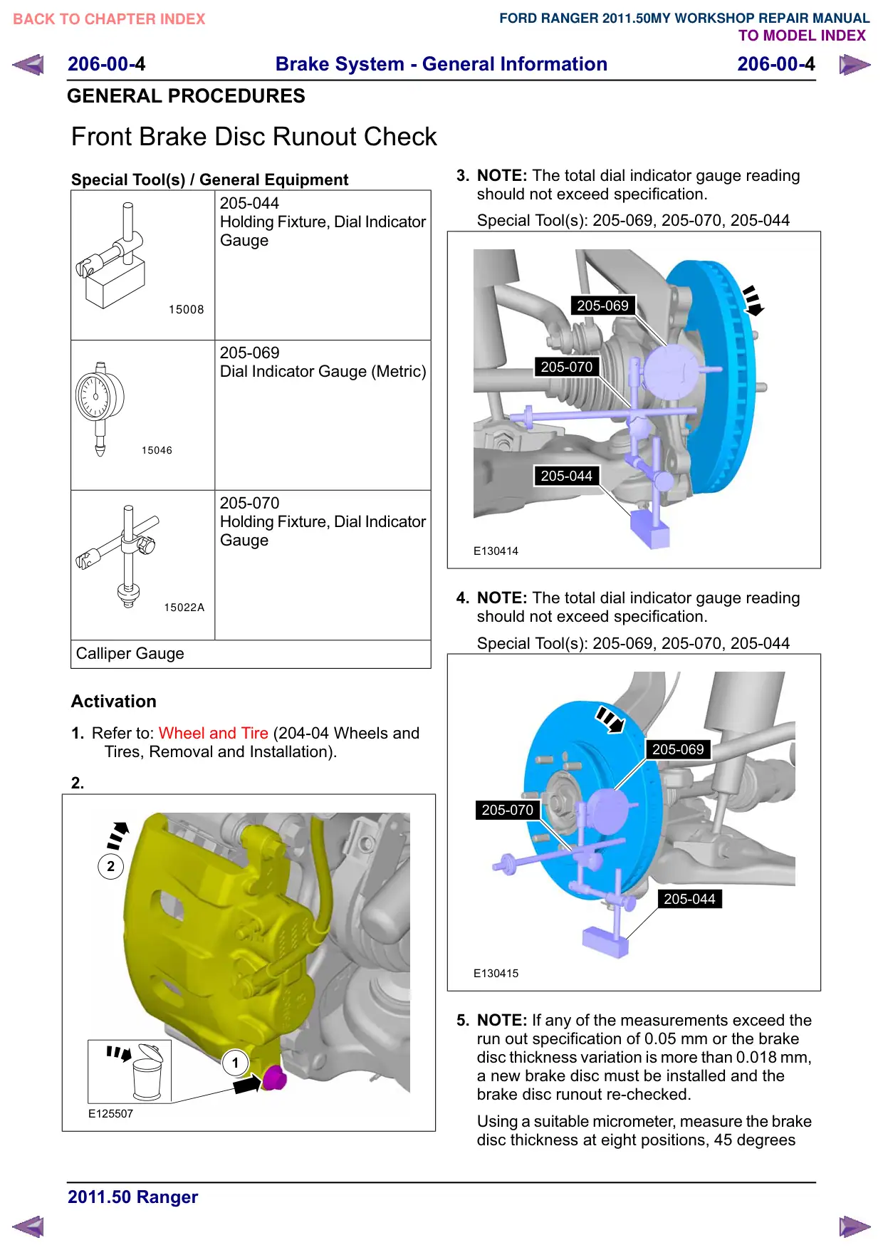
3. NOTE: The total dial indicator gauge reading
should not exceed specification.
Special Tool(s): 205-069, 205-070, 205-044
205-069
205-070
205-044
E130414
4. NOTE: The total dial indicator gauge reading
should not exceed specification.
Special Tool(s): 205-069, 205-070, 205-044
205-069
205-070
205-044
E130415
5. NOTE: If any of the measurements exceed the
run out specification of 0.05 mm or the brake
disc thickness variation is more than 0.018 mm,
a new brake disc must be installed and the
brake disc runout re-checked.
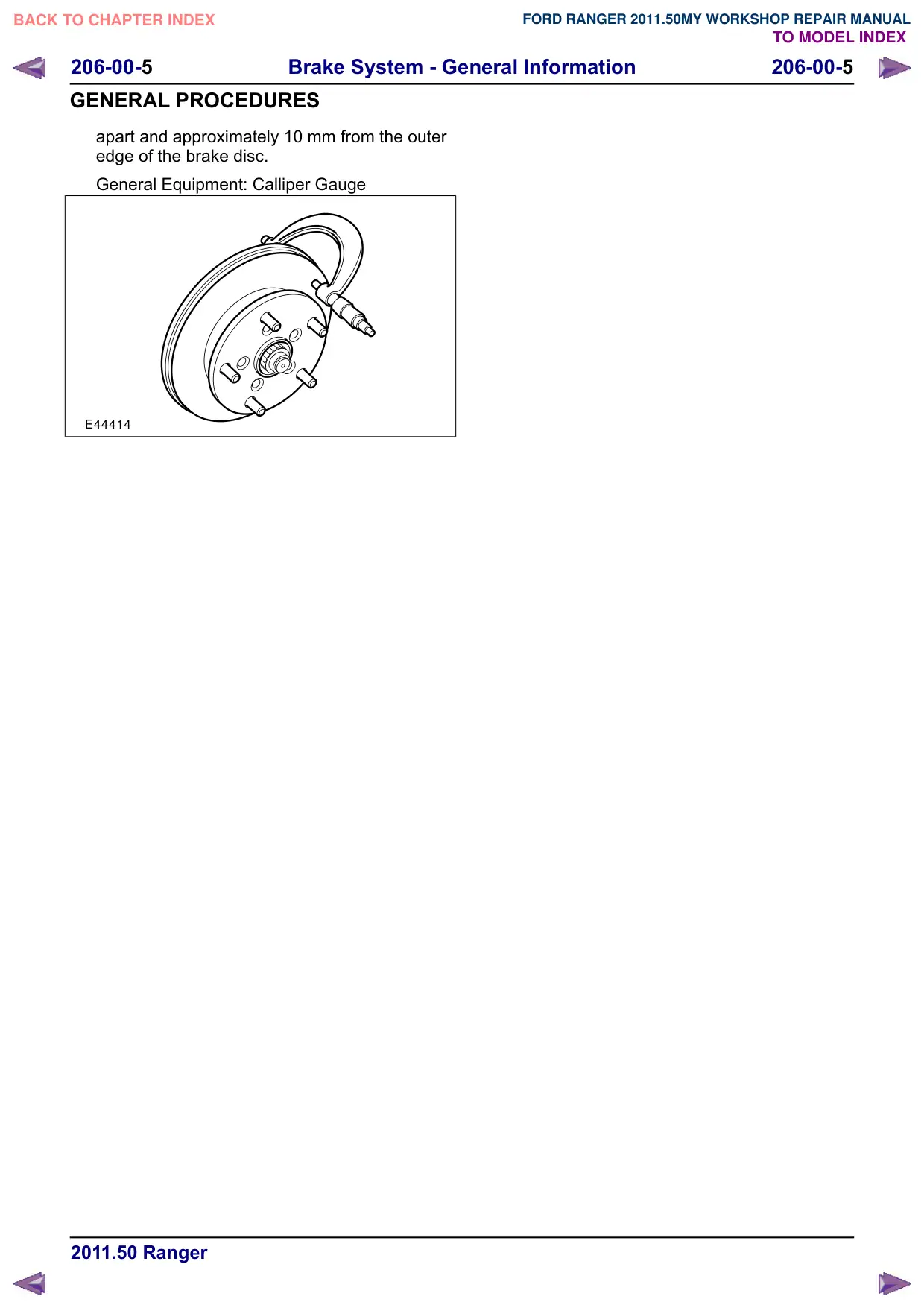
Using a suitable micrometer, measure the brake
disc thickness at eight positions, 45 degrees
Brake System - General Information
206-00-5
206-00-5
GENERAL PROCEDURES
apart and approximately 10 mm from the outer
edge of the brake disc.
General Equipment: Calliper Gauge
E44414
Brake System - General Information
206-00-6
206-00-6
GENERAL PROCEDURES
Brake System Leak Check
Check
1. NOTE: Brake fluid is water soluble and it is
possible that all evidence of fluid leakage
has been washed off if the vehicle has been
operated in rain or snow.
Check the brake fluid level. Add brake fluid
as necessary.
2. Apply the brakes several times and make
sure the pedal feel is not spongy. If
necessary, bleed the brake system.
For additional information, refer to Brake
System Bleeding in this section.
3. Check the brake fluid level and verify that
the fluid level is actually dropping.
4. NOTE: If the brake fluid level drops and no
external leak is evident, check for a brake
master cylinder bore end seal leak.
Locate and correct the external leak.
Brake System - General Information
206-00-7
206-00-7
GENERAL PROCEDURES
Brake System Bleeding(12 141 0)
General Equipment
Worldwide Diagnostic System (WDS)
Bleeding
All Vehicles
WARNING: Brake fluid contains polyglycol
ethers and polyglycols. Avoid contact with
the eyes. Wash hands thoroughly after
handling. If brake fluid contacts the eyes,
flush the eyes for 15 minutes with cold
running water. Get medical attention if
irritation persists. If taken internally, drink
water and induce vomiting. Get medical
attention immediately. Failure to follow
these instructions may result in personal
injury.
CAUTION: If brake fluid is spilt on the
paintwork, the affected area must be
immediately washed down with cold water.
NOTE: Make sure that the vehicle is standing on
a level surface.
NOTE: The system consists of separate circuits
for each front and diagonally opposite rear wheel.
Each circuit can be bled independently.
1.
CAUTION: The brake fluid reservoir must
remain full with new, clean brake fluid at all
times during bleeding.
Install the bleed tube to the bleed nipple.
2. Immerse the end of the bleed tube in a bleed
jar containing a small quantity of approved
brake fluid.
3. Position the bleed jar base at least 300 mm
above the bleed nipple to maintain fluid
pressure and prevent air leaking past the
threads of the bleed nipple.
4. Loosen the rear left bleed nipple by one-half
turn.
5. Operate the brake pedal fully (pumping brake
fluid and air into the bleed jar) and allow the
brake pedal to return to the rest position.
6. NOTE: Rear brakes only.
Rapidly operate the parking brake control
several times.
7. Fill the brake fluid reservoir to the MAX mark.
8. Continue operating the brake pedal until
air-free fluid is being pumped into the bleed
jar.
9. With the brake pedal fully depressed tighten
the bleed nipple.
10.
CAUTION: Make sure that the bleed
nipple cap is installed after bleeding the
brake line(s). This will prevent corrosion to
the bleed nipple. Failure to follow this
instruction may result in the bleed nipple
becoming seized.
Repeat the procedure for the remaining brake
lines in the following order:
1. Front left.
2. Front right.
3. Rear right.
Vehicles with anti-lock brakes
11. NOTE: This step is only necessary when
changing the brake fluid to remove the used
brake fluid from the hydraulic control unit
(HCU).
Using WDS, bleed the brake system.
Brake System - General Information
206-00-8
206-00-8
GENERAL PROCEDURES
Brake System Pressure Bleeding(12 141 0)
General Equipment
Worldwide Diagnostic System (WDS)
Brake/clutch system pressure bleeder/filler
Bleeding
All vehicles
WARNING: Brake fluid contains polyglycol
ethers and polyglycols. Avoid contact with
the eyes. Wash hands thoroughly after
handling. If brake fluid contacts the eyes,
flush the eyes for 15 minutes with cold
running water. Get medical attention if
irritation persists. If taken internally, drink
water and induce vomiting. Get medical
attention immediately. Failure to follow
these instructions may result in personal
injury.
CAUTION: If brake fluid is spilt on the
paintwork, the affected area must be
immediately washed down with cold water.
NOTE: Make sure that the vehicle is standing on
a level surface.
NOTE: The system consists of separate circuits
for each front and diagonally opposite rear wheel.
Each circuit can be bled independently.
1. Fill the brake fluid reservoir to the MAX mark.
2. CAUTIONS:
Make sure that the pressure within the
brake system does not exceed 1 bar.
Make sure that the pressure bleeding
equipment is filled with new brake fluid to
the correct specification.
Using the brake/clutch system pressure
bleeder/filler, pressure bleed the system in
accordance with the manufacturer's
instructions in the following order:
1. Rear left.
Rapidly operate the parking brake control
several times.
2. Front left.
3. Front right.
4. Rear right.
Rapidly operate the parking brake control
several times.
CAUTION: Make sure that the bleed nipple
cap is installed after bleeding the brake
line(s). This will prevent corrosion to the
bleed nipple. Failure to follow this
instruction may result in the bleed nipple
becoming seized.
3. Fill the brake fluid reservoir to the MAX mark
as necessary.
Vehicles with anti-lock brakes
4. NOTE: This step is only necessary when
changing the brake fluid to remove the used
brake fluid from the hydraulic control unit
(HCU).
Using :'6, bleed the brake system.