5 Body and Paint
5.1 Body
5.1.1 Body Structures - General
Information
CAUTION: Load carrying structures
should not be mounted onto an
existing load tray or load box.
When carrying out vehicle
conversions/modifications the following points
should be considered:
•
Make sure that the vehicle structural integrity
is maintained.
•
Do not drill into closed frame body members.
•
Make sure that the design for the body
alterations or additional structure disperse the
load evenly.
CAUTION: Uneven load distribution
couldresultinunacceptablehandling
and braking characteristics.
•
Re-paint metal edges after cutting or drilling.
All metal edges must comply with exterior
and interior protection legislation.
•
All fixings through the floor, sides or roof must
be sealed.
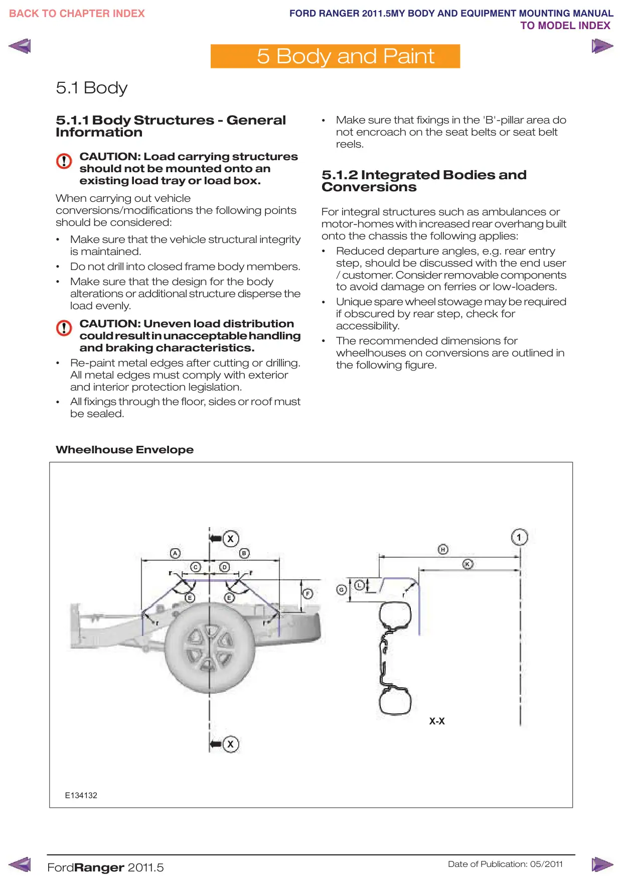
Wheelhouse Envelope
X
A
B
C
D
r
r
E
E
X
E134132
FordRanger 2011.5
•
Make sure that fixings in the 'B'-pillar area do
not encroach on the seat belts or seat belt
reels.
5.1.2 Integrated Bodies and
Conversions
For integral structures such as ambulances or
motor-homes with increased rear overhang built
onto the chassis the following applies:
•
Reduced departure angles, e.g. rear entry
step, should be discussed with the end user
/ customer. Consider removable components
to avoid damage on ferries or low-loaders.
•
Unique spare wheel stowage may be required
if obscured by rear step, check for
accessibility.
•
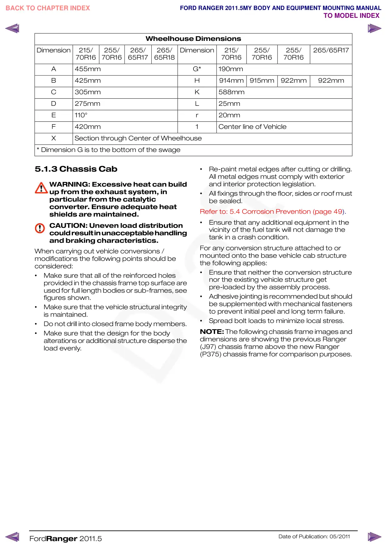
The recommended dimensions for
wheelhouses on conversions are outlined in
the following figure.
1
H
K
L
G
F
X-X
Date of Publication: 05/2011
Wheelhouse Dimensions
Dimension
215/
255/
265/
265/
Dimension
70R16
70R16
65R17
65R18
A
455mm
B
425mm
C
305mm
D
275mm
E
110°
F
420mm
X
Section through Center of Wheelhouse
* Dimension G is to the bottom of the swage
5.1.3 Chassis Cab
WARNING: Excessive heat can build
up from the exhaust system, in
particular from the catalytic
converter. Ensure adequate heat
shields are maintained.
CAUTION: Uneven load distribution
couldresultinunacceptablehandling
and braking characteristics.
When carrying out vehicle conversions /
modifications the following points should be
considered:
•
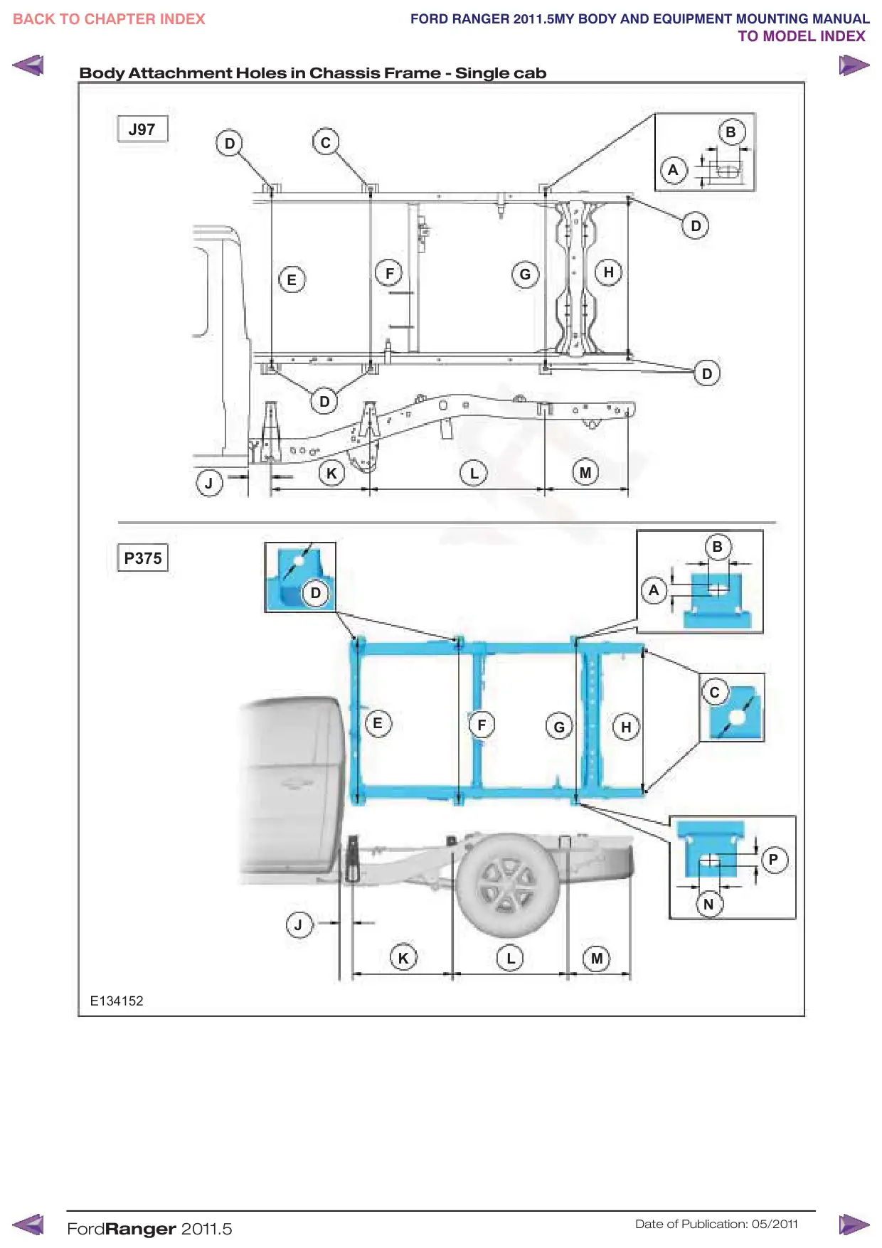
Make sure that all of the reinforced holes
provided in the chassis frame top surface are
used for full length bodies or sub-frames, see
figures shown.
•
Make sure that the vehicle structural integrity
is maintained.
•
Do not drill into closed frame body members.
•
Make sure that the design for the body
alterations or additional structure disperse the
load evenly.
FordRanger 2011.5
215/
255/
255/
265/65R17
70R16
70R16
70R16
G*
190mm
H
914mm
915mm
922mm
922mm
K
588mm
L
25mm
r
20mm
1
Center line of Vehicle
•
Re-paint metal edges after cutting or drilling.
All metal edges must comply with exterior
and interior protection legislation.
•
All fixings through the floor, sides or roof must
be sealed.
Refer to: 5.4 Corrosion Prevention (page 49).
•
Ensure that any additional equipment in the
vicinity of the fuel tank will not damage the
tank in a crash condition.
For any conversion structure attached to or
mounted onto the base vehicle cab structure
the following applies:
•
Ensure that neither the conversion structure
nor the existing vehicle structure get
pre-loaded by the assembly process.
•
Adhesive jointing is recommended but should
be supplemented with mechanical fasteners
to prevent initial peel and long term failure.
•
Spread bolt loads to minimize local stress.
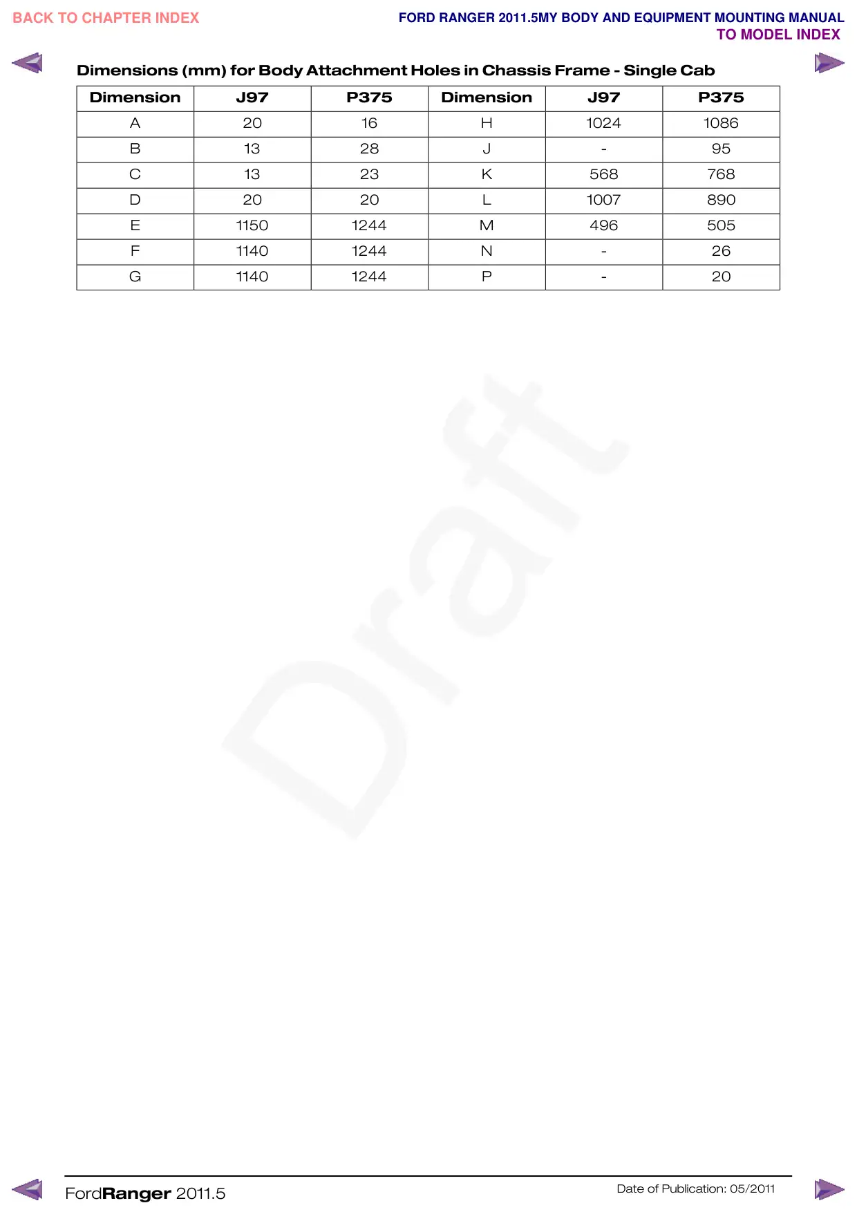
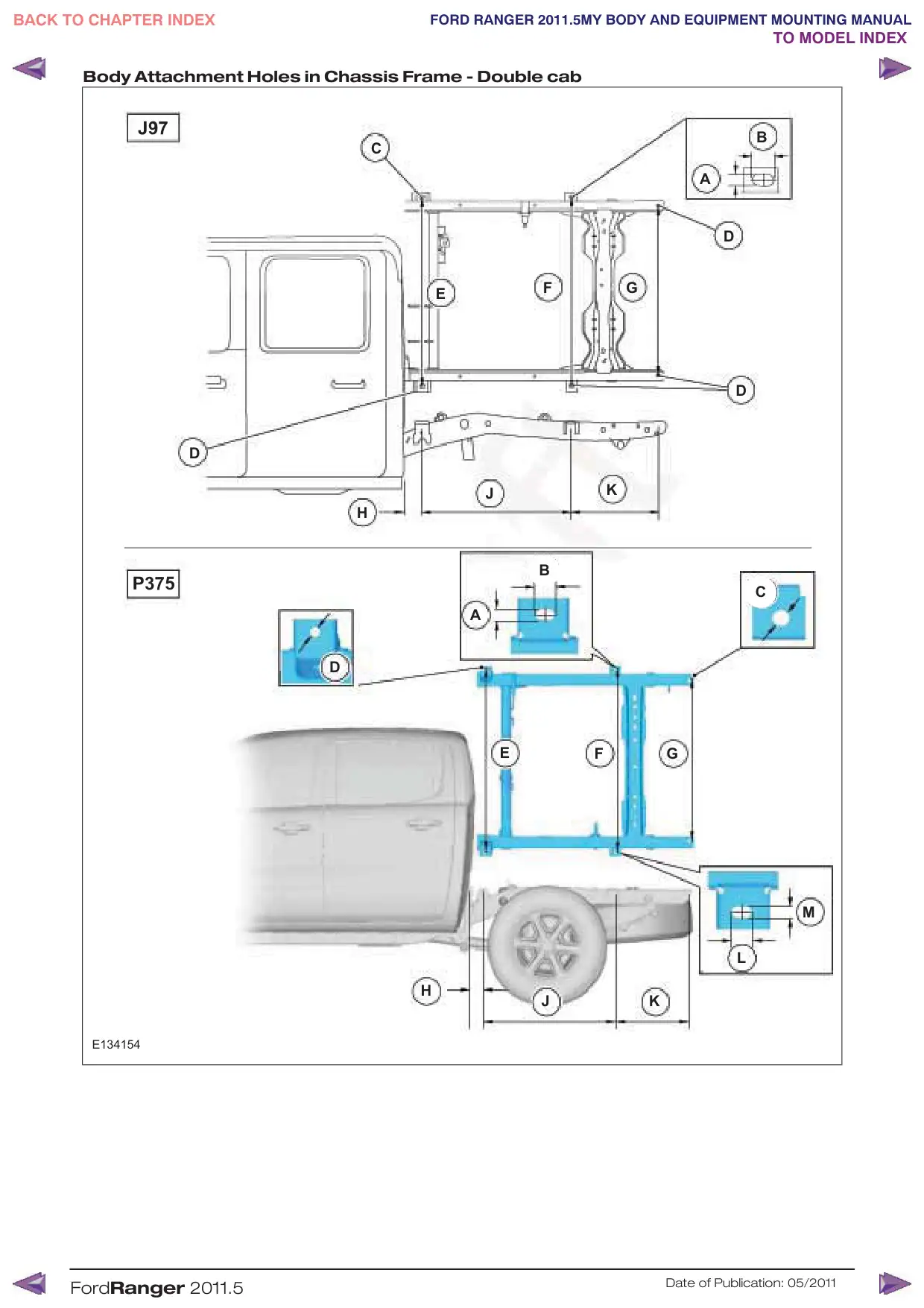
NOTE: The following chassis frame images and
dimensions are showing the previous Ranger
(J97) chassis frame above the new Ranger
(P375) chassis frame for comparison purposes.
Date of Publication: 05/2011
Body Attachment Holes in Chassis Frame - Single cab
J97
D
C
F
E
D
K
J
P375
D
E
J
K
E134152
FordRanger 2011.5
B
A
D
G
H
D
L
M
B
A
C
F
G
H
P
N
L
M
Date of Publication: 05/2011
Dimensions (mm) for Body Attachment Holes in Chassis Frame - Single Cab
Dimension
J97
P375
Dimension
J97
P375
A
20
16
B
13
28
C
13
23
D
20
20
E
1150
1244
F
1140
1244
G
1140
1244
FordRanger 2011.5
H
1024
1086
J
-
95
K
568
768
L
1007
890
M
496
505
N
-
26
P
-
20
Date of Publication: 05/2011
Body Attachment Holes in Chassis Frame - Double cab
C
D
H
D
H
E134154
FordRanger 2011.5
B
A
D
F
G
E
D
J
K
B
C
A
E
F
G
M
L
J
K
Date of Publication: 05/2011
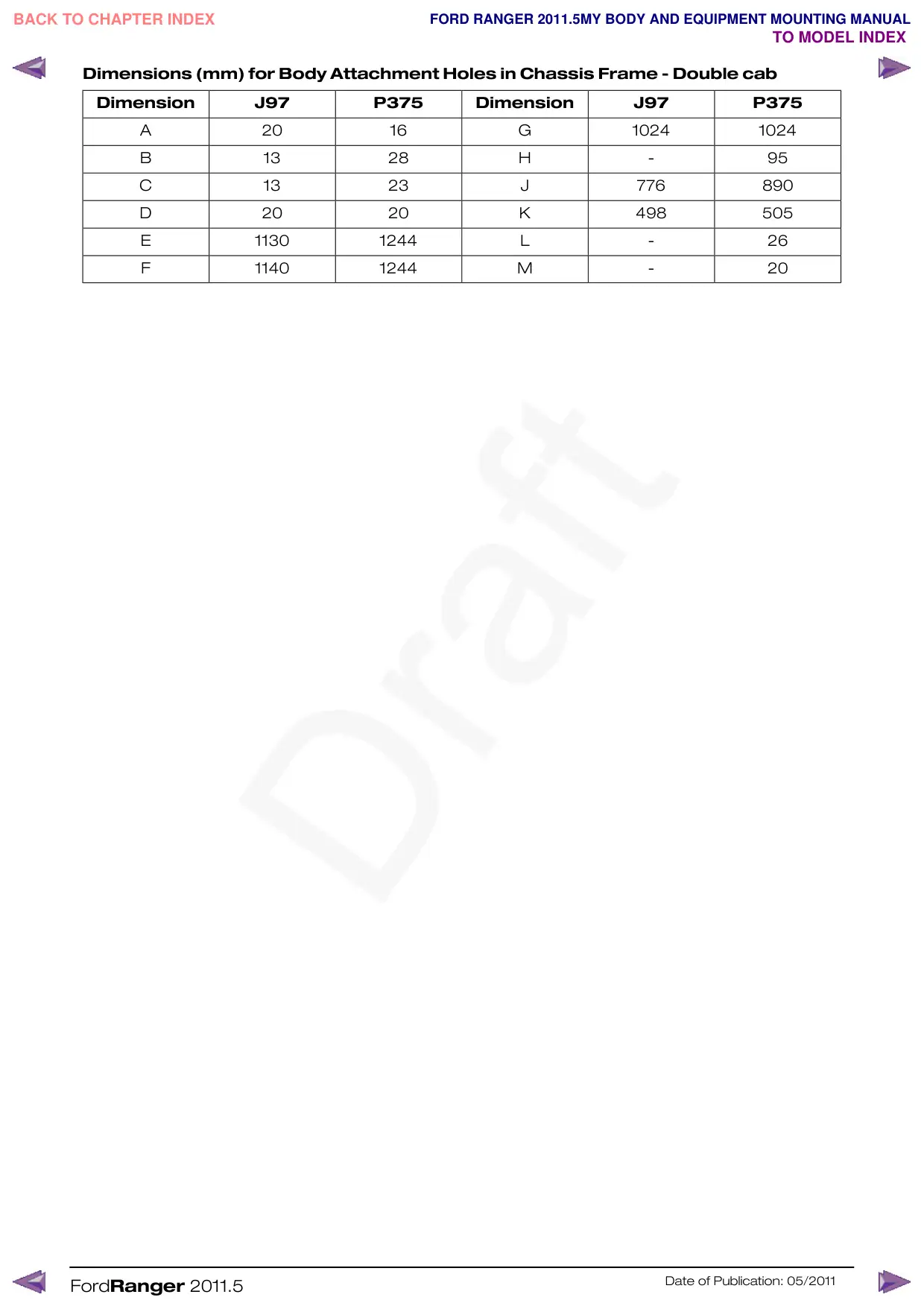
Dimensions (mm) for Body Attachment Holes in Chassis Frame - Double cab
Dimension
J97
P375
Dimension
J97
P375
A
20
16
B
13
28
C
13
23
D
20
20
E
1130
1244
F
1140
1244
FordRanger 2011.5
G
1024
1024
H
-
95
J
776
890
K
498
505
L
-
26
M
-
20
Date of Publication: 05/2011
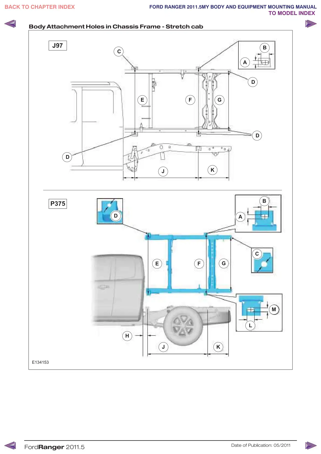
Body Attachment Holes in Chassis Frame - Stretch cab
C
E
D
D
H
E134153
FordRanger 2011.5
B
A
D
F
G
D
J
K
B
A
C
F
G
E
M
L
J
K
Date of Publication: 05/2011
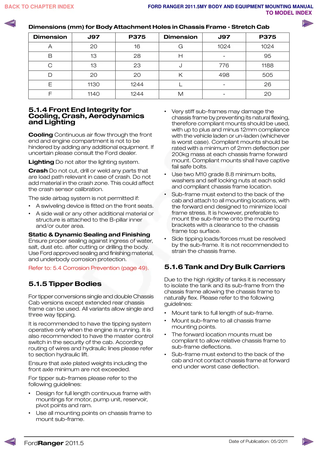
Dimensions (mm) for Body Attachment Holes in Chassis Frame - Stretch Cab
Dimension
J97
P375
Dimension
J97
P375
A
20
16
B
13
28
C
13
23
D
20
20
E
1130
1244
F
1140
1244
5.1.4 Front End Integrity for
Cooling, Crash, Aerodynamics
and Lighting
Cooling Continuous air flow through the front
end and engine compartment is not to be
hindered by adding any additional equipment. If
uncertain please consult the Ford dealer.
Lighting Do not alter the lighting system.
Crash Do not cut, drill or weld any parts that
are load path relevant in case of crash. Do not
add material in the crash zone. This could affect
the crash sensor calibration.
The side airbag system is not permitted if:
•
A swiveling device is fitted on the front seats.
•
A side wall or any other additional material or
structure is attached to the B-pillar inner
and/or outer area.
Static & Dynamic Sealing and Finishing
Ensure proper sealing against ingress of water,
salt, dust etc. after cutting or drilling the body.
Use Ford approved sealing and finishing material,
and underbody corrosion protection.
Refer to: 5.4 Corrosion Prevention (page 49).
5.1.5 Tipper Bodies
For tipper conversions single and double Chassis
Cab versions except extended rear chassis
frame can be used. All variants allow single and
three way tipping.
It is recommended to have the tipping system
operative only when the engine is running. It is
also recommended to have the master control
switch in the security of the cab. According
routing of wires and hydraulic lines please refer
to section hydraulic lift.
Ensure that axle plated weights including the
front axle minimum are not exceeded.
For tipper sub-frames please refer to the
following guidelines:
•
Design for full length continuous frame with
mountings for motor, pump unit, reservoir,
pivot points and ram.
•
Use all mounting points on chassis frame to
mount sub-frame.
FordRanger 2011.5
G
1024
1024
H
-
95
J
776
1188
K
498
505
L
-
26
M
-
20
•
Very stiff sub-frames may damage the
chassis frame by preventing its natural flexing,
therefore compliant mounts should be used,
with up to plus and minus 12mm compliance
with the vehicle laden or un-laden (whichever
is worst case). Compliant mounts should be
rated with a minimum of 2mm deflection per
200kg mass at each chassis frame forward
mount. Compliant mounts shall have captive
fail safe bolts.
•
Use two M10 grade 8.8 minimum bolts,
washers and self locking nuts at each solid
and compliant chassis frame location.
•
Sub-frame must extend to the back of the
cab and attach to all mounting locations, with
the forward end designed to minimize local
frame stress. It is however, preferable to
mount the sub-frame onto the mounting
brackets with a clearance to the chassis
frame top surface.
•
Side tipping loads/forces must be resolved
by the sub-frame. It is not recommended to
strain the chassis frame.
5.1.6 Tank and Dry Bulk Carriers
Due to the high rigidity of tanks it is necessary
to isolate the tank and its sub-frame from the
chassis frame allowing the chassis frame to
naturally flex. Please refer to the following
guidelines:
•
Mount tank to full length of sub-frame.
•
Mount sub-frame to all chassis frame
mounting points.
•
The forward location mounts must be
compliant to allow relative chassis frame to
sub-frame deflections.
Sub-frame must extend to the back of the
•
cab and not contact chassis frame at forward
end under worst case deflection.
Date of Publication: 05/2011
•
Compliant mounts should be used, with up
•
The load is evenly distributed (converter to
to plus and minus 12mm compliance with the
ensure owner’s information book identifies
vehicle laden or un-laden (whichever is worst
this limitation).
case). Compliant mounts should be rated with
a minimum of 2mm deflection per 200kg
mass at each chassis frame forward mount.
Compliant mounts shall have captive fail safe
bolts.
Use two M10 grade 8.8 minimum bolts,
•
washers and self lock nuts per chassis frame
mount bracket at each solid and compliant
location.
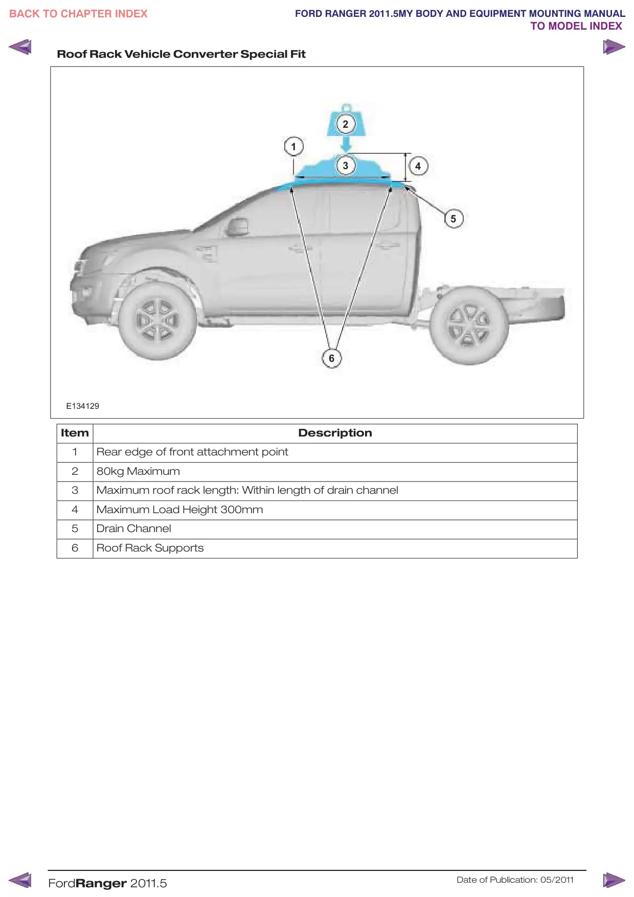
5.1.7 Roof Racks
Roof racks may be fitted to all variants as
illustrated in figure, providing the following is
satisfied:
•
The carried load does not exceed 80kg (Body
Builder to ensure owner’s hand book identifies
this limitation).
•
The carried load does not exceed 300mm
load height (converter to ensure owner’s
information book identifies this limitation).
FordRanger 2011.5
•
The rack and subsequent carried load is
supported in the roof drip rails irrespective of
rack retaining method.
Double Cab / Stretch Cab
The forgoing limitations are based on ensuring
body structure integrity, vehicle handling, braking
and plated axle weights. Such considerations
must also be applied to any double cab and
stretch cab applications, in particular steering,
braking and front axle plated weight and the
extra continuous loads on the “A” pillar, which
should not exceed 60 kg total incremental load.
Ensure that the planned loaded vehicle operates
within its designed Center of Gravity condition.
For details please consult the Ford dealer.
Date of Publication: 05/2011
Roof Rack Vehicle Converter Special Fit
1
E134129
Item
1
Rear edge of front attachment point
2
80kg Maximum
3
Maximum roof rack length: Within length of drain channel
4
Maximum Load Height 300mm
5
Drain Channel
6
Roof Rack Supports
FordRanger 2011.5
2
3
4
5
6
Description
Date of Publication: 05/2011
5.2 Air Bag Supplemental Restraint System (SRS)
5.2.1 Air Bags
Front Seats
Side airbags are not compatible with swiveling
front seats.
Do not specify the base vehicle with side airbags
when planning to retrofit a swiveling device on
the front seats and/or an armrest on the outer
side of the front seats, this may affect the
function and/or deployment of the side airbags.
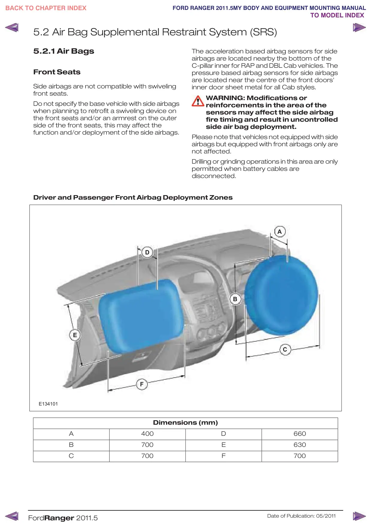
Driver and Passenger Front Airbag Deployment Zones
D
E
F
E134101
Dimensions (mm)
A
400
B
700
C
700
FordRanger 2011.5
The acceleration based airbag sensors for side
airbags are located nearby the bottom of the
C-pillar inner for RAP and DBL Cab vehicles. The
pressure based airbag sensors for side airbags
are located near the centre of the front doors'
inner door sheet metal for all Cab styles.
WARNING: Modifications or
reinforcements in the area of the
sensors may affect the side airbag
fire timing and result in uncontrolled
side air bag deployment.
Please note that vehicles not equipped with side
airbags but equipped with front airbags only are
not affected.
Drilling or grinding operations in this area are only
permitted when battery cables are
disconnected.
A
B
C
D
660
E
630
F
700
Date of Publication: 05/2011
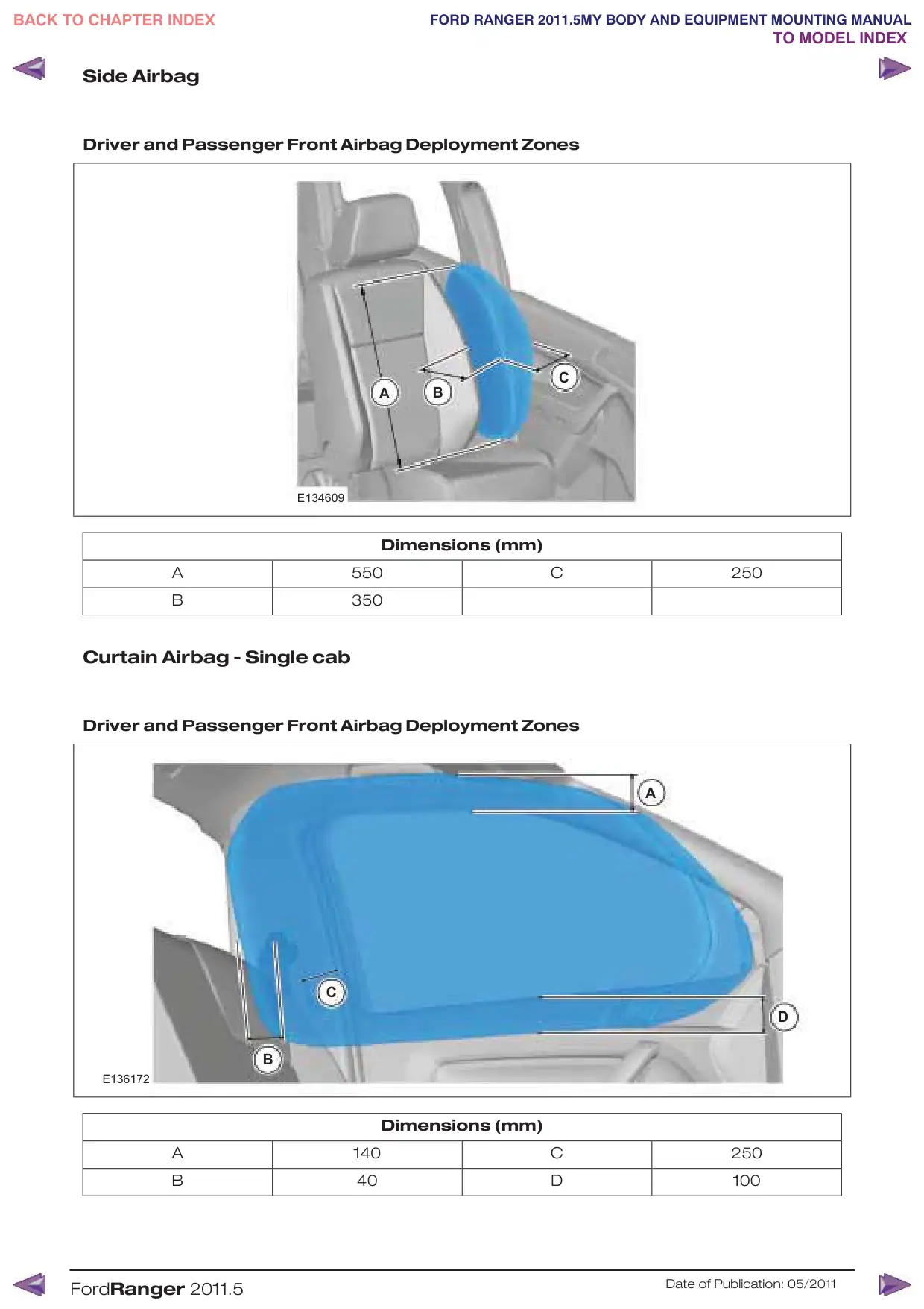
Side Airbag
Driver and Passenger Front Airbag Deployment Zones
A
E134609
Dimensions (mm)
A
550
B
350
Curtain Airbag - Single cab
Driver and Passenger Front Airbag Deployment Zones
C
B
E136172
Dimensions (mm)
A
140
B
40
FordRanger 2011.5
C
B
C
250
A
D
C
250
D
100
Date of Publication: 05/2011
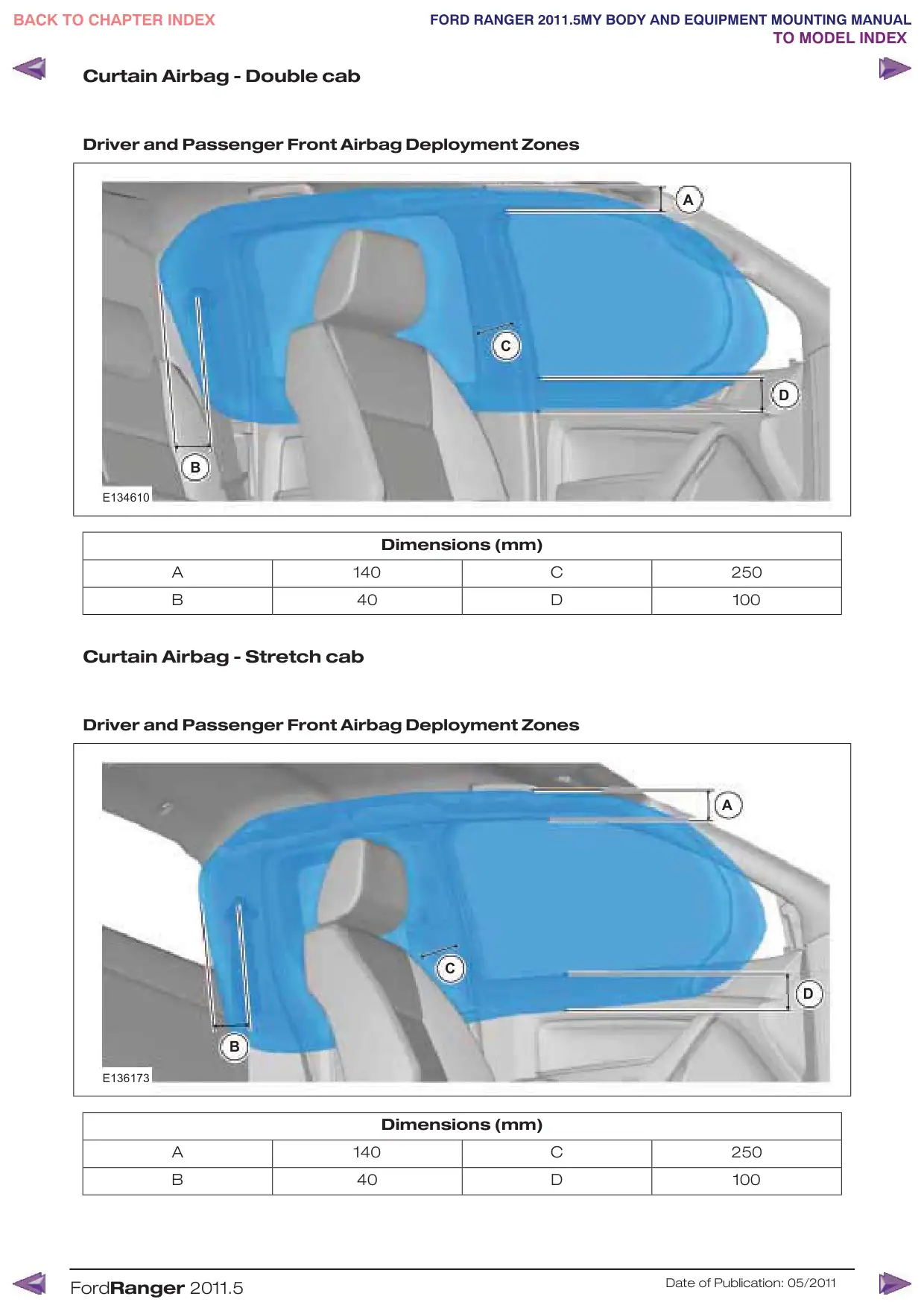
Curtain Airbag - Double cab
Driver and Passenger Front Airbag Deployment Zones
B
E134610
Dimensions (mm)
A
140
B
40
Curtain Airbag - Stretch cab
Driver and Passenger Front Airbag Deployment Zones
B
E136173
Dimensions (mm)
A
140
B
40
FordRanger 2011.5
A
C
D
C
250
D
100
A
C
D
C
250
D
100
Date of Publication: 05/2011
5.3 Safety Belt System
WARNING: Follow removal and
installation procedures for the seat
belt system to ensure correct
function of the restraints system.
The removal and reinstallation of the seat belt,
restrainer or any component of the seat belt
system should be avoided. However if removal
and re-installation of the system is required
during the conversion, follow the removal and
installation guidelines of the seat belt system as
described in the workshop manual. Please
consult your local National Sales Company
representative for further information.
When removing the seat belt system, a seat belt
webbing forked retainer should be applied to
the webbing 200mm below the webbing button
stop. This prevents a situation where all the
webbing runs back into the retractor and the
retractor becomes locked.
When reinstalling, fit the retractor to the body
first and gently pull the webbing out of the
retractor to allow fitment of the D loop. Then
remove the forked retainer. If the retractor is
locked, allow a small amount of webbing to reel
back into the retractor to allow the webbing lock
to release. Do not attempt to release the
retractor by pulling on the webbing with
significant force or by manually interfering with
the locking mechanism.
FordRanger 2011.5
Date of Publication: 05/2011
5.4 Corrosion Prevention
5.4.1 General
Avoid drilling into closed frame body members
to avoid the risk of corrosion from swarf.
If drilling is required, however:
•
Re-paint metal edges and protect against
corrosion after cutting or drilling operations.
•
Endeavor to remove all swarf from inside the
side member and treat to prevent corrosion.
•
Apply corrosion protection inside and outside
of the chassis frame.
5.4.2 Repairing Damaged Paint
After cutting or reworking any sheet metal on
the vehicle the damaged paint must be repaired.
Ensure all materials are compatible with the
relevant Ford specifications and maintain the
original performance where possible.
5.4.3 Under Body Protection and
Material
WARNING: Do not over-coat or
contaminate surfaces of
components such as brakes or
catalytic converters.
Ensure all materials are compatible with the
relevant Ford specifications and maintain the
original performance where possible.
Some proprietary products affect the original
coatings. For specifications of corrosion
protection materials, please consult your local
National Sales Company representative.
5.4.4 Painting Road Wheels
WARNING: Do not paint wheel clamp
surfaces in contact with other
wheels, brake drum or disc, hub and
holes or surface under wheel nuts.
Any further treatment in these areas
may affect the wheel clamp
performance and the vehicle safety.
Mask the wheel when changing the
color or repairing paint.
5.4.5 Contact Corrosion
When using different materials with a different
electrochemical potential, ensure that materials
are isolated from each other to prevent contact
corrosion caused by a potential difference.
Use appropriate isolation materials.
Where possible, choose materials with low level
of electrochemical potential difference.
FordRanger 2011.5
Date of Publication: 05/2011
5.5 Frame and Body Mounting
5.5.1 Mounting Points and Tubing
Holes on frame are a result of the production
process. They are not designed for fixing
additional equipment. Always use chassis
mounts as shown in sub frame for low floor or
other equipment. If additional fixings are required
please follow the recommendation given in the
figure shown. This does not apply to areas of
load applications such as spring fixings or
damper fixings.
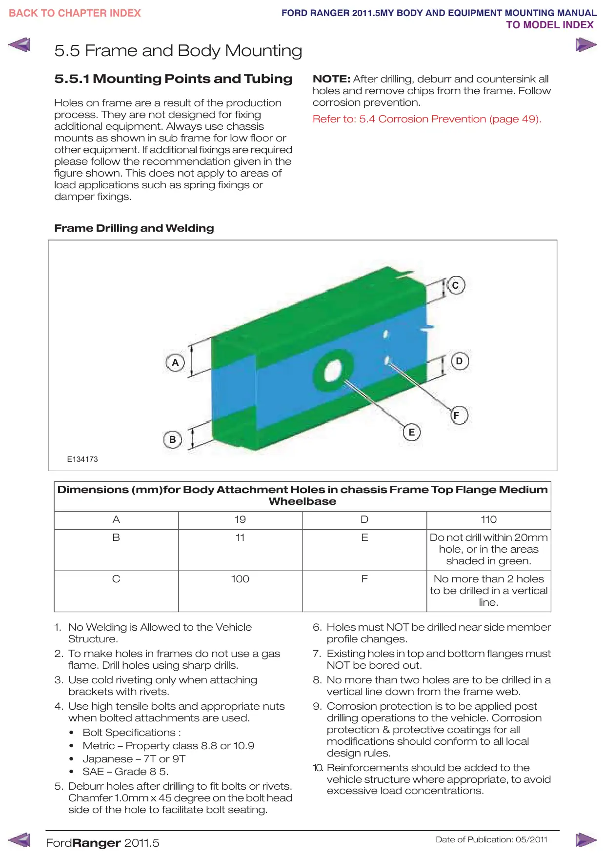
Frame Drilling and Welding
A
B
E134173
Dimensions (mm)for Body Attachment Holes in chassis Frame Top Flange Medium
Wheelbase
A
19
B
11
C
100
1. No Welding is Allowed to the Vehicle
Structure.
2. To make holes in frames do not use a gas
flame. Drill holes using sharp drills.
3. Use cold riveting only when attaching
brackets with rivets.
4. Use high tensile bolts and appropriate nuts
when bolted attachments are used.
•
Bolt Specifications :
•
Metric – Property class 8.8 or 10.9
•
Japanese – 7T or 9T
•
SAE – Grade 8 5.
5. Deburr holes after drilling to fit bolts or rivets.
Chamfer 1.0mm x 45 degree on the bolt head
side of the hole to facilitate bolt seating.
FordRanger 2011.5
NOTE: After drilling, deburr and countersink all
holes and remove chips from the frame. Follow
corrosion prevention.
Refer to: 5.4 Corrosion Prevention (page 49).
C
D
F
E
D
110
E
Do not drill within 20mm
hole, or in the areas
shaded in green.
F
No more than 2 holes
to be drilled in a vertical
line.
6. Holes must NOT be drilled near side member
profile changes.
7. Existing holes in top and bottom flanges must
NOT be bored out.
8. No more than two holes are to be drilled in a
vertical line down from the frame web.
9. Corrosion protection is to be applied post
drilling operations to the vehicle. Corrosion
protection & protective coatings for all
modifications should conform to all local
design rules.
10. Reinforcements should be added to the
vehicle structure where appropriate, to avoid
excessive load concentrations.
Date of Publication: 05/2011
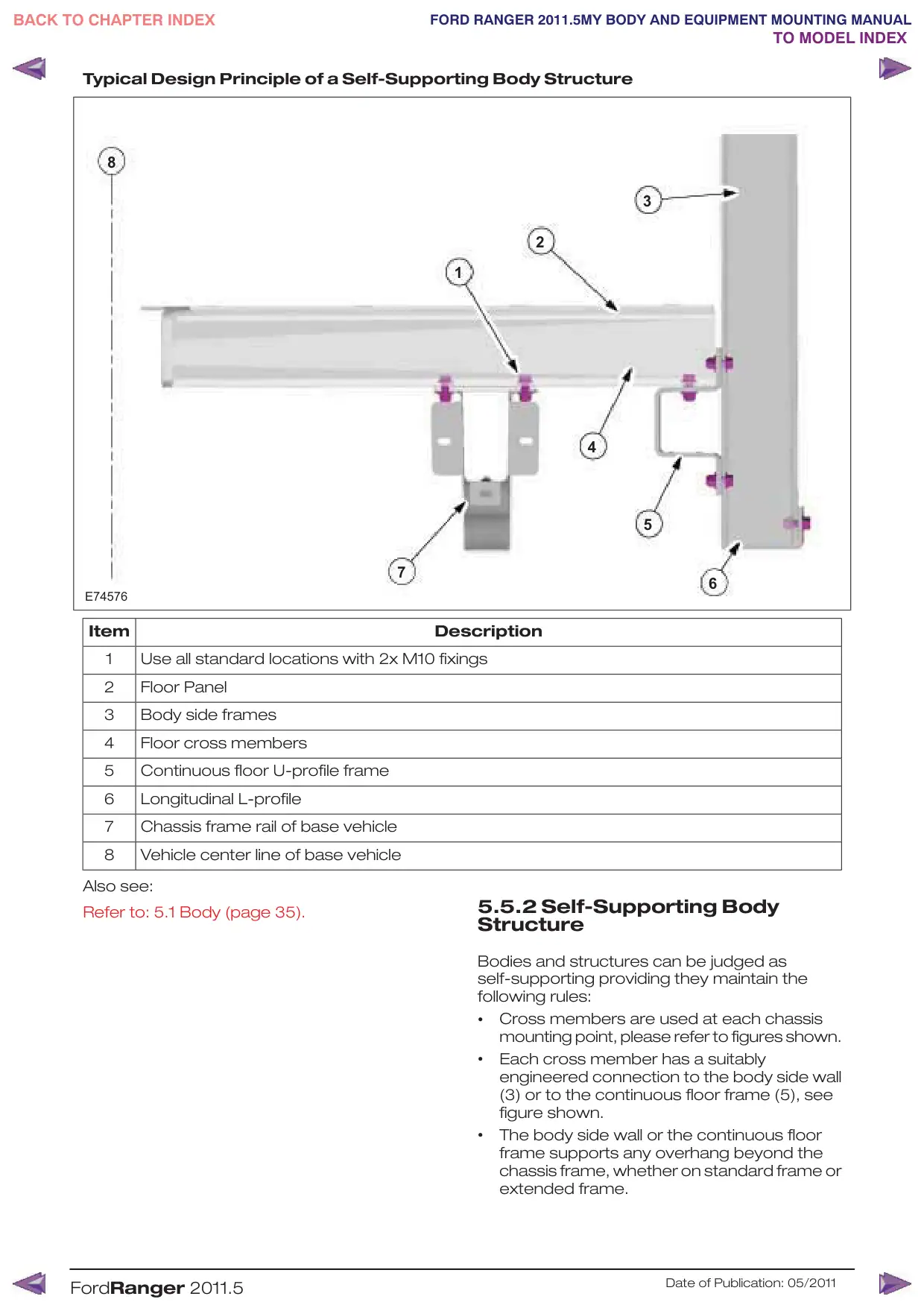
Typical Design Principle of a Self-Supporting Body Structure
8
7
E74576
Item
1
Use all standard locations with 2x M10 fixings
2
Floor Panel
3
Body side frames
4
Floor cross members
5
Continuous floor U-profile frame
6
Longitudinal L-profile
7
Chassis frame rail of base vehicle
8
Vehicle center line of base vehicle
Also see:
Refer to: 5.1 Body (page 35).
FordRanger 2011.5
3
2
1
4
5
6
Description
5.5.2 Self-Supporting Body
Structure
Bodies and structures can be judged as
self-supporting providing they maintain the
following rules:
•
Cross members are used at each chassis
mounting point, please refer to figures shown.
•
Each cross member has a suitably
engineered connection to the body side wall
(3) or to the continuous floor frame (5), see
figure shown.
•
The body side wall or the continuous floor
frame supports any overhang beyond the
chassis frame, whether on standard frame or
extended frame.
Date of Publication: 05/2011
Alternatively, the self-supporting body structure
•
Holes should be in groups of two (2), either
can also be designed as shown in figure shown.
vertically spaced at 30 to 35mm from chassis
frame top and/or bottom surface, or
•
This concept is based on a self-supporting
structure where the floor is mounted directly
onto the top surface of the chassis frame.
•
See figure shown for a generic vehicle cross
section where the cross members and
opposing out riggers are flush with the surface
of the chassis frame side members.
•
It is important to the overall function of the
vehicle structure that the out riggers are each
connected to a continuous longitudinal floor
side frame or a structural body side structure
assembly.
Low floor-re-work for guidance only:
•
Engineer unique cross members and
out-riggers spaced at approximately 600mm
maximum pitch.
Out-rigger moment to be re-acted with
•
cross-member between chassis frame with
common through bolts where possible.
•
Drill frame and add spacer tubes.
Refer to: 5.5 Frame and Body Mounting (page
50).
•
Out-rigger outboard ends should be attached
to load bearing body side / floor edge frame
or body side structure (including over wheel
support).
•
Structural wheel box should maintain
longitudinal continuity with a rigid attachment
to the floor edge frame or to the body side
structure.
•
Floor boards should be substantially attached
to cross members and outriggers, but not to
the chassis frame top surface.
•
Low floor exhaust heat shields.
5.5.3 Frame Drilling and Tube
Reinforcing
The chassis frame may be drilled and reinforcing
spacer tubes may be welded in place, providing
the following is applied:
•
Adhere to all details shown in figure.
•
Drill and weld only side walls of the chassis
frame.
•
Locate and drill holes accurately, using a drill
guide to ensure holes are square to frame
vertical center line (note: allow for side
member draft angle).
Drill undersize and ream out to size.
•
•
Endeavor to remove all swarf from inside side
member, and treat to prevent corrosion.
•
Fully weld each end of the tube and grind flat
and square, in groups if applicable. Be aware
of side member draft angle.
•
Apply corrosion protection inside and outside
of the chassis frame.
Refer to: 5.4 Corrosion Prevention (page 49).
FordRanger 2011.5
horizontally at 50mm minimum pitch, 30 to
35mm from top and/or bottom chassis frame
surface.
•
Always use M10 bolts with grade 8.8
minimum.
•
Do not position tubes at the medium chassis
frame height, this may create “oil canning” of
the deep section side walls.
•
Where possible, the outrigger moments
should be resolved by matching inner cross
members between the chassis side members
inline with the outriggers.
•
A diameter of 16.5mm is the maximum
allowable hole size in the chassis frame side
wall, irrespective of the usage.
Avoid drilling into closed frame body members
to avoid the risk of corrosion from swarf.
Refer to: 5.4 Corrosion Prevention (page 49).
Drilling and welding of frames and body structure
have to be conducted following the program
guidelines. Please consult the Ford dealer for
details.
5.5.4 Ancillary Equipment - Sub
Frame Mounting
Typical sub-frames and longitudinal members
for flatbed and low or drop-side bodies or
equipment exceeding the standard or Regular
Production Order frame length should adhere
to the following guidelines:
Flat-beds and low bodies mounted on integral
•
longitudinal members (channel or box section
metal – not wood) must use both sides of all
frame mounting brackets.
•
Longitudinal members must be relieved at
the front end if they are to contact the chassis
frame top surface, to minimize stress
concentrations. It is preferable however, to
mount the longitudinal onto the mounting
brackets, with a clearance to the chassis
frame top surface.
•
Each set of brackets must use two (2) x M10
bolts grade 8.8 minimum.
•
Minimum floor heights will require wheel arch
boxes to clear the rear tires, see Vehicle Data
sheets for relevant tire jounce.
5.5.5 Area for Fitting Additional
Body Attachments to the Rear of
the Bumper.
NOTE: With the vehicle on level ground and with
all measurements taken rear ward of the bumper
bar edge: The area designated for the fitting of
attachment is defined as 220mm horizontally by
95mm vertical downward to the road surface,
with a max width of 1390mm about vehicle
center line.
Date of Publication: 05/2011
It is not the manufactures recommendation to
fit additional body attachments (Tow bars, Steps,
Bicycle racks & Carriers) outside of the
designated area.
5.5.6 Water Tank on Camper
Vehicles
NOTE: It is recommended that a decal or
label is fitted adjacent to the filler
aperture identifying the correct fluid to
be used, for example: 'Water only' for
water tanks.
FordRanger 2011.5
Date of Publication: 05/2011
A
H
About This Manual..................................................4
Hardware—Specifications..................................23
Index
Additional External Lamps..................................34
Aids for Vehicle Entry and Exit............................16
Air Bags..................................................................45
Air Bag Supplemental Restraint System
(SRS)....................................................................45
Alternative Type Approval.....................................5
Ancillary Equipment - Sub Frame Mounting....52
Area for Fitting Additional Body Attachments to
the Rear of the Bumper....................................52
B
Battery and Cables..............................................32
Battery Information..............................................32
Body.......................................................................35
Body Structures - General Information............35
C
Center of Gravity..................................................26
Chassis Cab Body - Basic Dimensions and
Weights.................................................................19
Chassis Cab..........................................................36
Commercial and Legal Aspects...........................5
Contact Corrosion...............................................49
Conversion Affect on Fuel Economy and
Performance........................................................10
Conversion Affects on Parking Aids..................16
Conversion Homologation....................................7
Corrosion Prevention..........................................49
D
Drilling and Welding................................................6
Driver Field of View...............................................16
Driver Reach Zones..............................................16
E
Electrically operated Door Mirrors.....................34
Electromagnetic Compatibility (EMC).................8
Exterior Lighting....................................................34
F
Frame and Body Mounting................................50
Frame Drilling and Tube Reinforcing.................52
Front, Rear and Side Under-run Protection.....22
Front End Integrity for Cooling, Crash,
Aerodynamics and Lighting..............................42
G
General Component Package Guidelines........16
General..................................................................49
General Product Safety Requirement.................5
Generator and Alternator...................................33
54
How to Use This Manual.......................................4
I
Important Safety Instructions...............................4
Integrated Bodies and Conversions.................35
Introduction.............................................................4
J
Jacking....................................................................11
K
Kerb Weights.........................................................21
L
Lamps – Hazard / Direction Indication..............34
Legal and Vehicle Type Approval.........................5
Legal Obligations and Liabilities............................5
Lifting.......................................................................13
Load Distribution—Specifications......................24
Load Distribution Calculations - Driver and
Passenger Weight Distribution........................24
M
Minimum Requirements for Brake system and
Load Apportioning Valves...................................6
Mounting Points and Tubing..............................50
N
Noise, Vibration and Harshness (NVH)..............14
P
Package and Ergonomics—Specifications.......17
Package and Ergonomics...................................16
Painting Road Wheels.........................................49
Product Liability.......................................................6
R
Recommended Body Dimensions.....................17
Repairing Damaged Paint...................................49
Restraints System..................................................6
Reversing Lamps.................................................34
Road Safety.............................................................6
Roof Racks............................................................43
S
Safety Belt System...............................................48
Self-Supporting Body Structure.........................51
Suggested Antenna Location..............................9
Suspension System..............................................31
T
Tank and Dry Bulk Carriers................................42
Terminology............................................................5
Tipper Bodies.......................................................42
Towing capacities...............................................29
Towing Requirements........................................29
Towing Specifications.........................................30
Towing...................................................................29
U
Under Body Protection and Material...............49
V
Vehicle Duty Cycle Guidelines...........................10
Vehicle Ride and Handling Attributes................10
Vehicle Transportation Aids and Vehicle
Storage................................................................15
W
Warnings, Cautions and Notes in This
Manual...................................................................4
Warranty on Ford Vehicles...................................5
Water Tank on Camper Vehicles......................53
Index
55