5.1.4 Integridade da dianteira para
5.1.4 Front End Integrity for
Texto da página
Link desta página: https://ranger.mbrace.com.br/implementos/32
Imagem: https://ranger.mbrace.com.br/img/implementos/32.webp
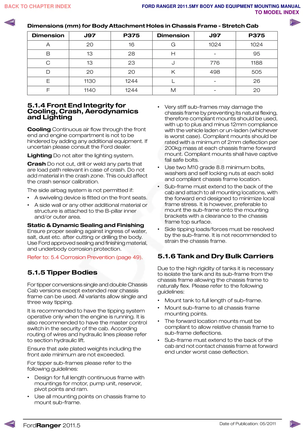
Dimensions (mm) for Body Attachment Holes in Chassis Frame - Stretch Cab
Dimension
J97
P375
Dimension
J97
P375
A
20
16
B
13
28
C
13
23
D
20
20
E
1130
1244
F
1140
1244
5.1.4 Front End Integrity for
Cooling, Crash, Aerodynamics
and Lighting
Cooling Continuous air flow through the front
end and engine compartment is not to be
hindered by adding any additional equipment. If
uncertain please consult the Ford dealer.
Lighting Do not alter the lighting system.
Crash Do not cut, drill or weld any parts that
are load path relevant in case of crash. Do not
add material in the crash zone. This could affect
the crash sensor calibration.
The side airbag system is not permitted if:
•
A swiveling device is fitted on the front seats.
•
A side wall or any other additional material or
structure is attached to the B-pillar inner
and/or outer area.
Static & Dynamic Sealing and Finishing
Ensure proper sealing against ingress of water,
salt, dust etc. after cutting or drilling the body.
Use Ford approved sealing and finishing material,
and underbody corrosion protection.
Refer to: 5.4 Corrosion Prevention (page 49).
5.1.5 Tipper Bodies
For tipper conversions single and double Chassis
Cab versions except extended rear chassis
frame can be used. All variants allow single and
three way tipping.
It is recommended to have the tipping system
operative only when the engine is running. It is
also recommended to have the master control
switch in the security of the cab. According
routing of wires and hydraulic lines please refer
to section hydraulic lift.
Ensure that axle plated weights including the
front axle minimum are not exceeded.
For tipper sub-frames please refer to the
following guidelines:
•
Design for full length continuous frame with
mountings for motor, pump unit, reservoir,
pivot points and ram.
•
Use all mounting points on chassis frame to
mount sub-frame.
FordRanger 2011.5
G
1024
1024
H
-
95
J
776
1188
K
498
505
L
-
26
M
-
20
•
Very stiff sub-frames may damage the
chassis frame by preventing its natural flexing,
therefore compliant mounts should be used,
with up to plus and minus 12mm compliance
with the vehicle laden or un-laden (whichever
is worst case). Compliant mounts should be
rated with a minimum of 2mm deflection per
200kg mass at each chassis frame forward
mount. Compliant mounts shall have captive
fail safe bolts.
•
Use two M10 grade 8.8 minimum bolts,
washers and self locking nuts at each solid
and compliant chassis frame location.
•
Sub-frame must extend to the back of the
cab and attach to all mounting locations, with
the forward end designed to minimize local
frame stress. It is however, preferable to
mount the sub-frame onto the mounting
brackets with a clearance to the chassis
frame top surface.
•
Side tipping loads/forces must be resolved
by the sub-frame. It is not recommended to
strain the chassis frame.
5.1.6 Tank and Dry Bulk Carriers
Due to the high rigidity of tanks it is necessary
to isolate the tank and its sub-frame from the
chassis frame allowing the chassis frame to
naturally flex. Please refer to the following
guidelines:
•
Mount tank to full length of sub-frame.
•
Mount sub-frame to all chassis frame
mounting points.
•
The forward location mounts must be
compliant to allow relative chassis frame to
sub-frame deflections.
Sub-frame must extend to the back of the
•
cab and not contact chassis frame at forward
end under worst case deflection.
Date of Publication: 05/2011