100-00-1
General Information
100-00-1
.
SECTION 100-00 General Information
VEHICLE APPLICATION: 2012.0Ranger
CONTENTS
DESCRIPTION AND OPERATION
About This Manual..............................................................................................................
How to Use This Manual....................................................................................................
Circuit Code........................................................................................................................
Wire Insulation Specification (Temperature).......................................................................
Connector Code - Component, GND and Splice................................................................
Connector Code - Harness Connectors.............................................................................
Wire Color Code.................................................................................................................
Symbols Glossary...............................................................................................................
PAGE
100-00-2
100-00-2
100-00-2
100-00-6
100-00-6
100-00-7
100-00-7
100-00-8
100-00-2
General Information
100-00-2
DESCRIPTION AND OPERATION
About This Manual
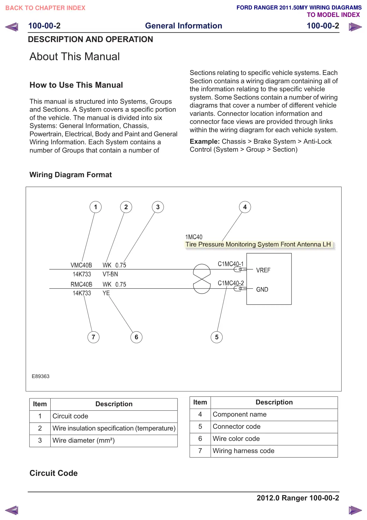
How to Use This Manual
This manual is structured into Systems, Groups
and Sections. A System covers a specific portion
of the vehicle. The manual is divided into six
Systems: General Information, Chassis,
Powertrain, Electrical, Body and Paint and General
Wiring Information. Each System contains a
number of Groups that contain a number of
Wiring Diagram Format
1
2
3
7
6
E89363
Item
Description
1
Circuit code
2
Wire insulation specification (temperature)
3
Wire diameter (mm²)
Circuit Code
Sections relating to specific vehicle systems. Each
Section contains a wiring diagram containing all of
the information relating to the specific vehicle
system. Some Sections contain a number of wiring
diagrams that cover a number of different vehicle
variants. Connector location information and
connector face views are provided through links
within the wiring diagram for each vehicle system.
Example: Chassis > Brake System > Anti-Lock
Control (System > Group > Section)
4
5
Item
Description
4
Component name
5
Connector code
6
Wire color code
7
Wiring harness code
2012.0 Ranger 100-00-2
100-00-3
General Information
100-00-3
DESCRIPTION AND OPERATION
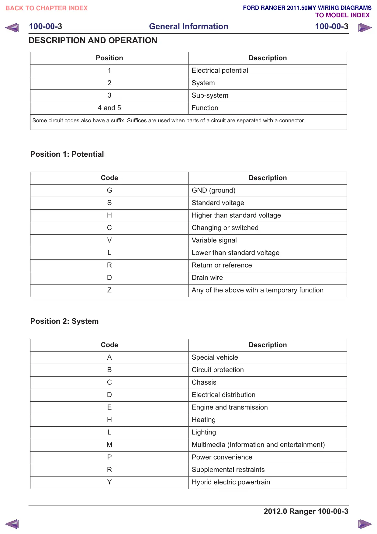
Position
1
2
3
4 and 5
Some circuit codes also have a suffix. Suffices are used when parts of a circuit are separated with a connector.
Position 1: Potential
Code
G
S
H
C
V
L
R
D
Z
Position 2: System
Code
A
B
C
D
E
H
L
M
P
R
Y
Description
Electrical potential
System
Sub-system
Function
Description
GND (ground)
Standard voltage
Higher than standard voltage
Changing or switched
Variable signal
Lower than standard voltage
Return or reference
Drain wire
Any of the above with a temporary function
Description
Special vehicle
Circuit protection
Chassis
Electrical distribution
Engine and transmission
Heating
Lighting
Multimedia (Information and entertainment)
Power convenience
Supplemental restraints
Hybrid electric powertrain
2012.0 Ranger 100-00-3
100-00-4
General Information
100-00-4
DESCRIPTION AND OPERATION
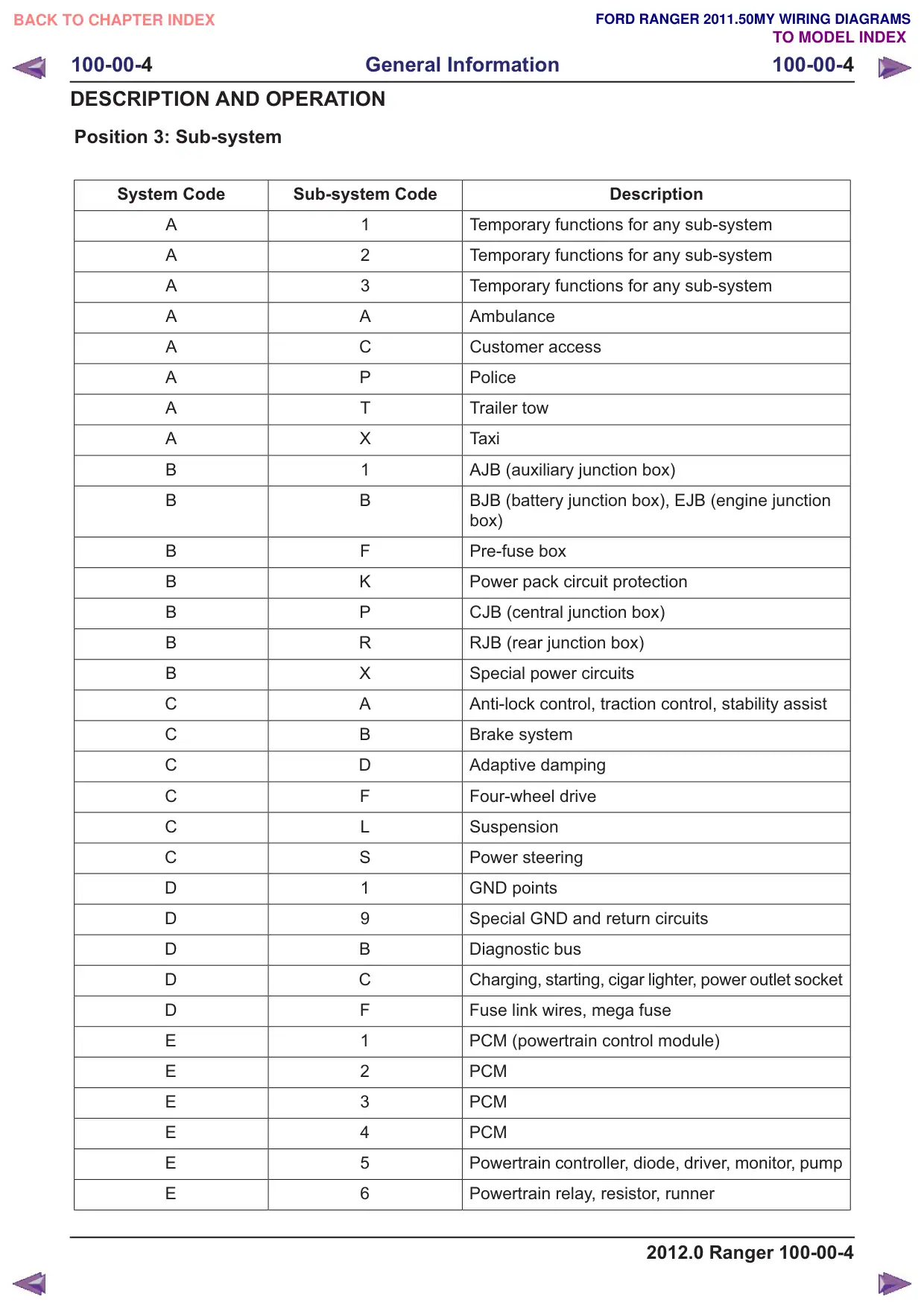
Position 3: Sub-system
System Code
Sub-system Code
A
1
A
2
A
3
A
A
A
C
A
P
A
T
A
X
B
1
B
B
B
F
B
K
B
P
B
R
B
X
C
A
C
B
C
D
C
F
C
L
C
S
D
1
D
9
D
B
D
C
D
F
E
1
E
2
E
3
E
4
E
5
E
6
Description
Temporary functions for any sub-system
Temporary functions for any sub-system
Temporary functions for any sub-system
Ambulance
Customer access
Police
Trailer tow
Taxi
AJB (auxiliary junction box)
BJB (battery junction box), EJB (engine junction
box)
Pre-fuse box
Power pack circuit protection
CJB (central junction box)
RJB (rear junction box)
Special power circuits
Anti-lock control, traction control, stability assist
Brake system
Adaptive damping
Four-wheel drive
Suspension
Power steering
GND points
Special GND and return circuits
Diagnostic bus
Charging, starting, cigar lighter, power outlet socket
Fuse link wires, mega fuse
PCM (powertrain control module)
PCM
PCM
PCM
Powertrain controller, diode, driver, monitor, pump
Powertrain relay, resistor, runner
2012.0 Ranger 100-00-4
100-00-5
General Information
100-00-5
DESCRIPTION AND OPERATION
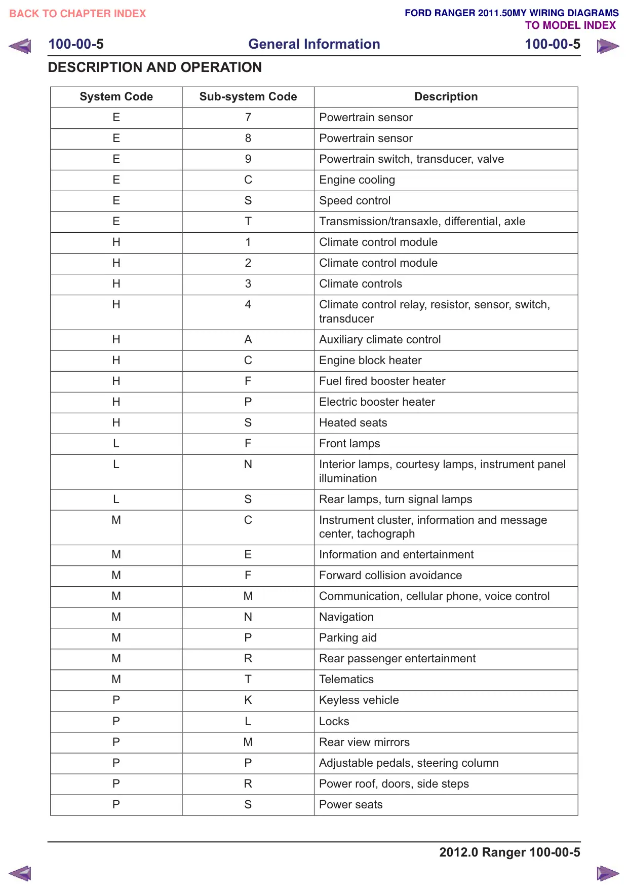
System Code
Sub-system Code
E
7
E
8
E
9
E
C
E
S
E
T
H
1
H
2
H
3
H
4
H
A
H
C
H
F
H
P
H
S
L
F
L
N
L
S
M
C
M
E
M
F
M
M
M
N
M
P
M
R
M
T
P
K
P
L
P
M
P
P
P
R
P
S
Description
Powertrain sensor
Powertrain sensor
Powertrain switch, transducer, valve
Engine cooling
Speed control
Transmission/transaxle, differential, axle
Climate control module
Climate control module
Climate controls
Climate control relay, resistor, sensor, switch,
transducer
Auxiliary climate control
Engine block heater
Fuel fired booster heater
Electric booster heater
Heated seats
Front lamps
Interior lamps, courtesy lamps, instrument panel
illumination
Rear lamps, turn signal lamps
Instrument cluster, information and message
center, tachograph
Information and entertainment
Forward collision avoidance
Communication, cellular phone, voice control
Navigation
Parking aid
Rear passenger entertainment
Telematics
Keyless vehicle
Locks
Rear view mirrors
Adjustable pedals, steering column
Power roof, doors, side steps
Power seats
2012.0 Ranger 100-00-5
100-00-6
General Information
100-00-6
DESCRIPTION AND OPERATION
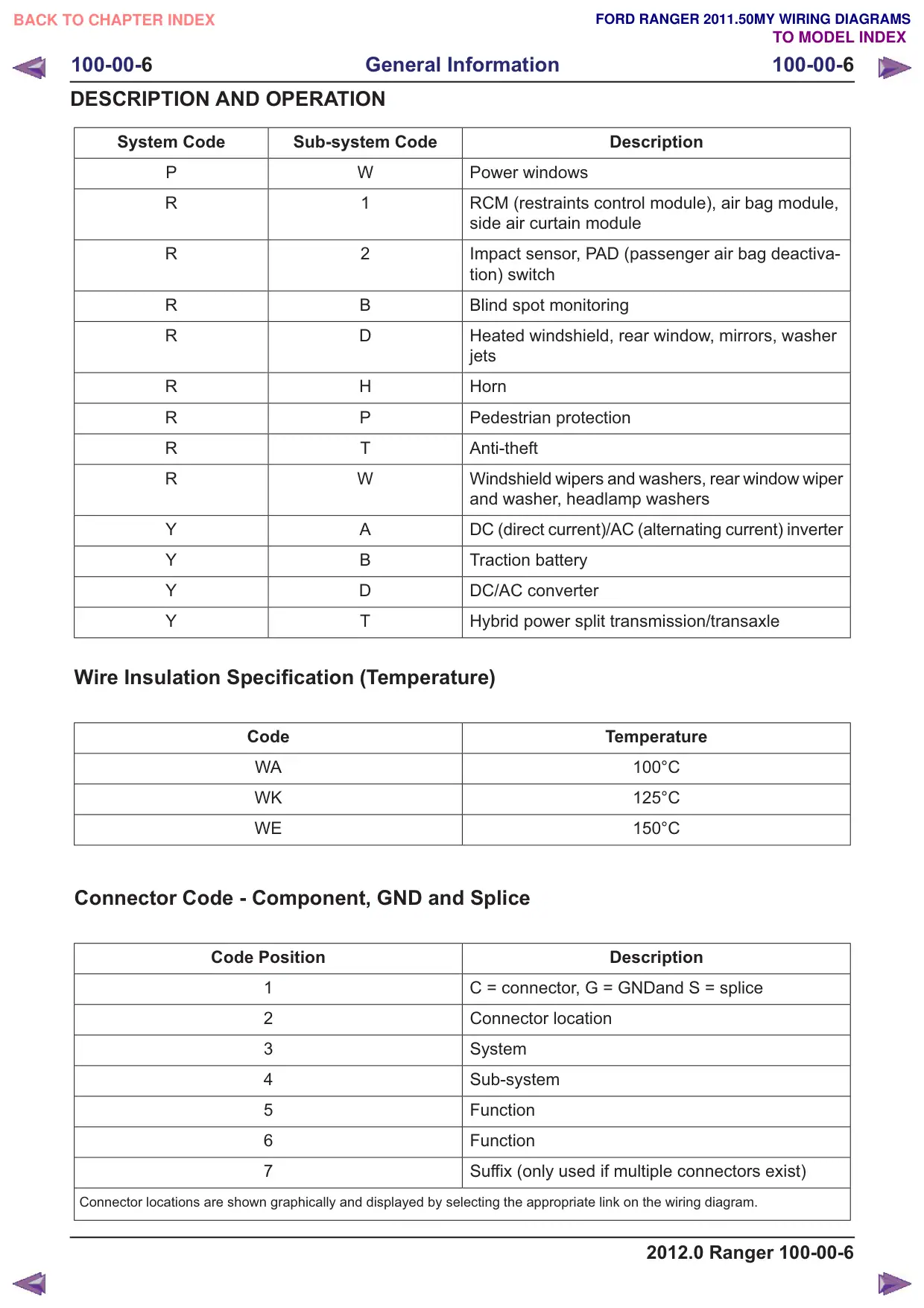
System Code
Sub-system Code
P
W
R
1
R
2
R
B
R
D
R
H
R
P
R
T
R
W
Y
A
Y
B
Y
D
Y
T
Wire Insulation Specification (Temperature)
Code
WA
WK
WE
Connector Code - Component, GND and Splice
Code Position
1
2
3
4
5
6
7
Connector locations are shown graphically and displayed by selecting the appropriate link on the wiring diagram.
Description
Power windows
RCM (restraints control module), air bag module,
side air curtain module
Impact sensor, PAD (passenger air bag deactiva-
tion) switch
Blind spot monitoring
Heated windshield, rear window, mirrors, washer
jets
Horn
Pedestrian protection
Anti-theft
Windshield wipers and washers, rear window wiper
and washer, headlamp washers
DC (direct current)/AC (alternating current) inverter
Traction battery
DC/AC converter
Hybrid power split transmission/transaxle
Temperature
100°C
125°C
150°C
Description
C = connector, G = GNDand S = splice
Connector location
System
Sub-system
Function
Function
Suffix (only used if multiple connectors exist)
2012.0 Ranger 100-00-6
100-00-7
General Information
100-00-7
DESCRIPTION AND OPERATION
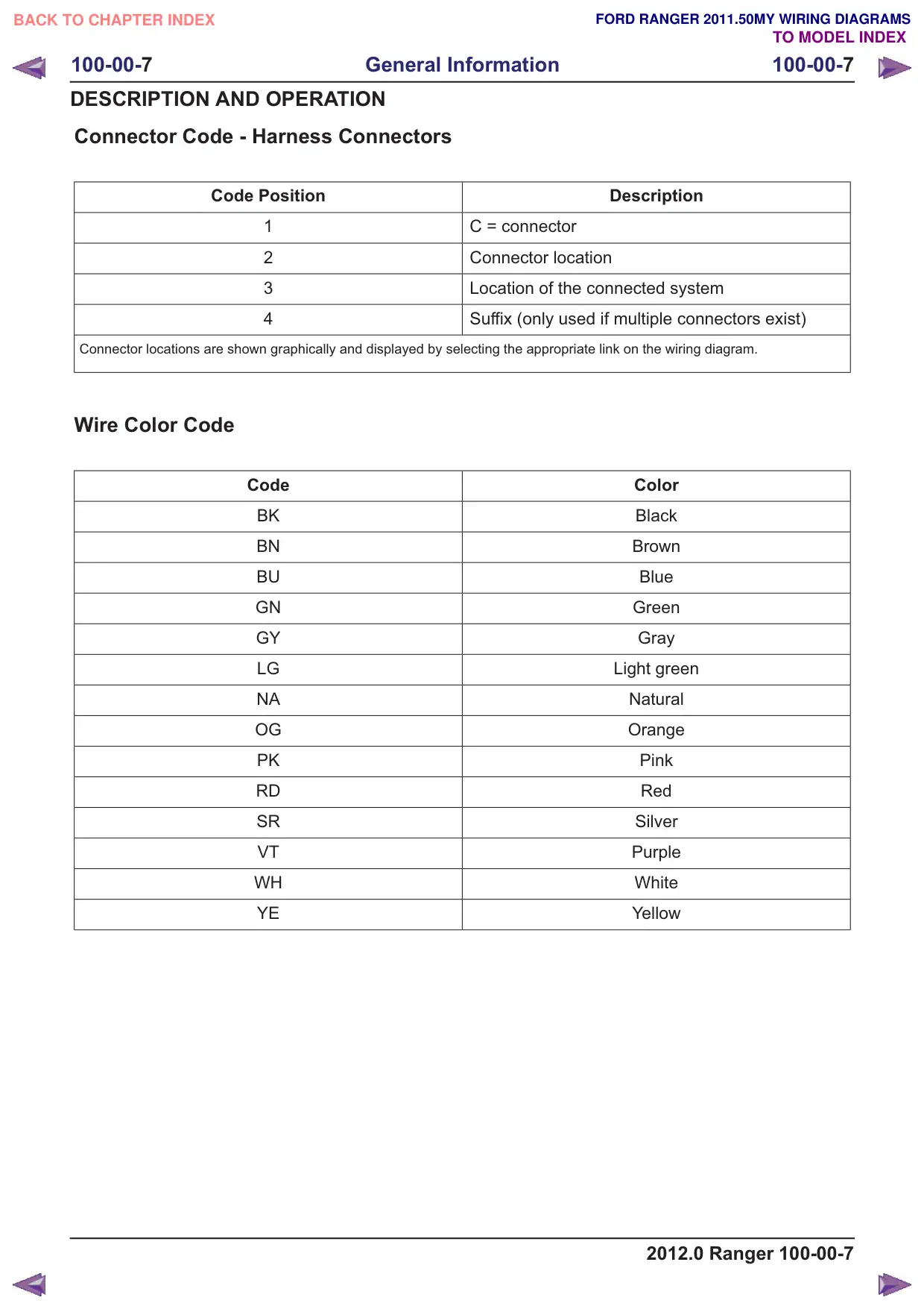
Connector Code - Harness Connectors
Code Position
1
2
3
4
Connector locations are shown graphically and displayed by selecting the appropriate link on the wiring diagram.
Wire Color Code
Code
BK
BN
BU
GN
GY
LG
NA
OG
PK
RD
SR
VT
WH
YE
Description
C = connector
Connector location
Location of the connected system
Suffix (only used if multiple connectors exist)
Color
Black
Brown
Blue
Green
Gray
Light green
Natural
Orange
Pink
Red
Silver
Purple
White
Yellow
2012.0 Ranger 100-00-7
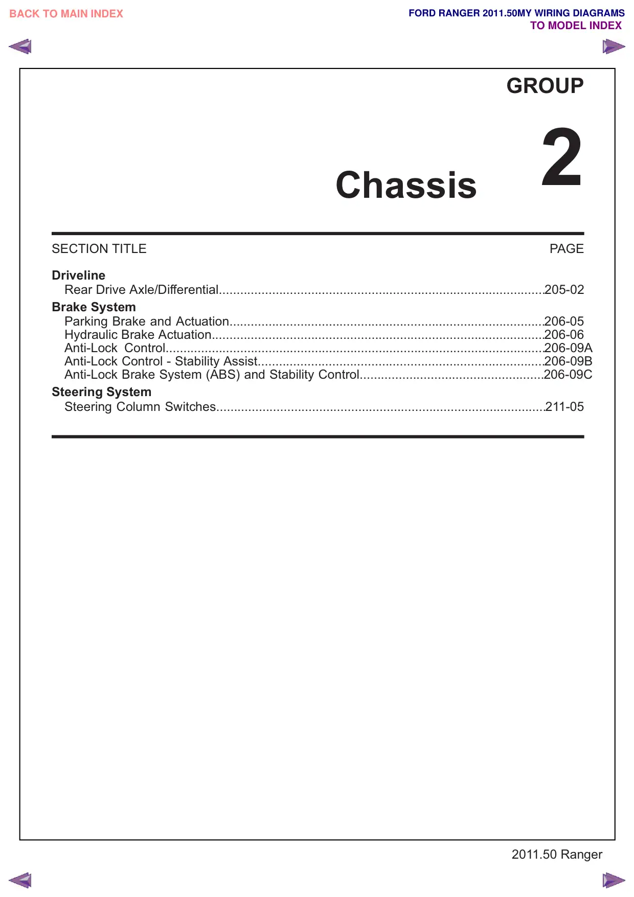
SECTION TITLE
Driveline
Rear Drive Axle/Differential............................................................................................205-02
Brake System
Parking Brake and Actuation.........................................................................................206-05
Hydraulic Brake Actuation..............................................................................................206-06
Anti-Lock Control...........................................................................................................206-09A
Anti-Lock Control - Stability Assist.................................................................................206-09B
Anti-Lock Brake System (ABS) and Stability Control....................................................206-09C
Steering System
Steering Column Switches.............................................................................................211-05
GROUP
Chassis 2
PAGE