501-14-5
Handles, Locks, Latches and Entry Systems
501-14-5
DESCRIPTION AND OPERATION
General
When one of the buttons on the remote control is
pressed, a coded HF radio signal is sent from the
transmitter in the mechanical key. This signal is
received by the RF receiver located in the BCM
(body control module), which decodes the signal.
If the coded signal is valid, the BCM will operate
the latches.
Unlocking is confirmed by one long flash of the turn
signal lamps, when the unlocking is completed.
There are various circumstances in which remote
unlocking is not possible:
The radio transmitter or receiver is overloaded
because of radio interference.
The key (electronics) is damaged.
The battery in the key is discharged.
The overload protection of the door latches is
active (after too many operations).
As well as remote keyless entry, the vehicle can
be locked and unlocked using the lock cylinder in
the driver's door. If RKE is not fitted, the vehicle
can also been unlocked using the lock cylinder in
the passenger's door. The lock cylinder is
mechanically connected to a switch, which is linked
to the BCM.
Double Locking
The double locking system has the same
functionality of central locking but also prevents
the doors from being opened from inside using the
interior door handles.
The double locking function is actuated if one of
the following conditions is satisfied:
A key is inserted into a door cylinder lock and
turned to the "locking" position twice within 3
seconds.
The locking button on the remote transmitter is
pressed twice within 3 seconds.
Confirmation that the vehicle is double locked is
also given by two short flashes of the turn signal
lamps, when the double locking process is
completed. The ordinary central locking in this case
will be signaled by a single short flash of the turn
signal lamps.
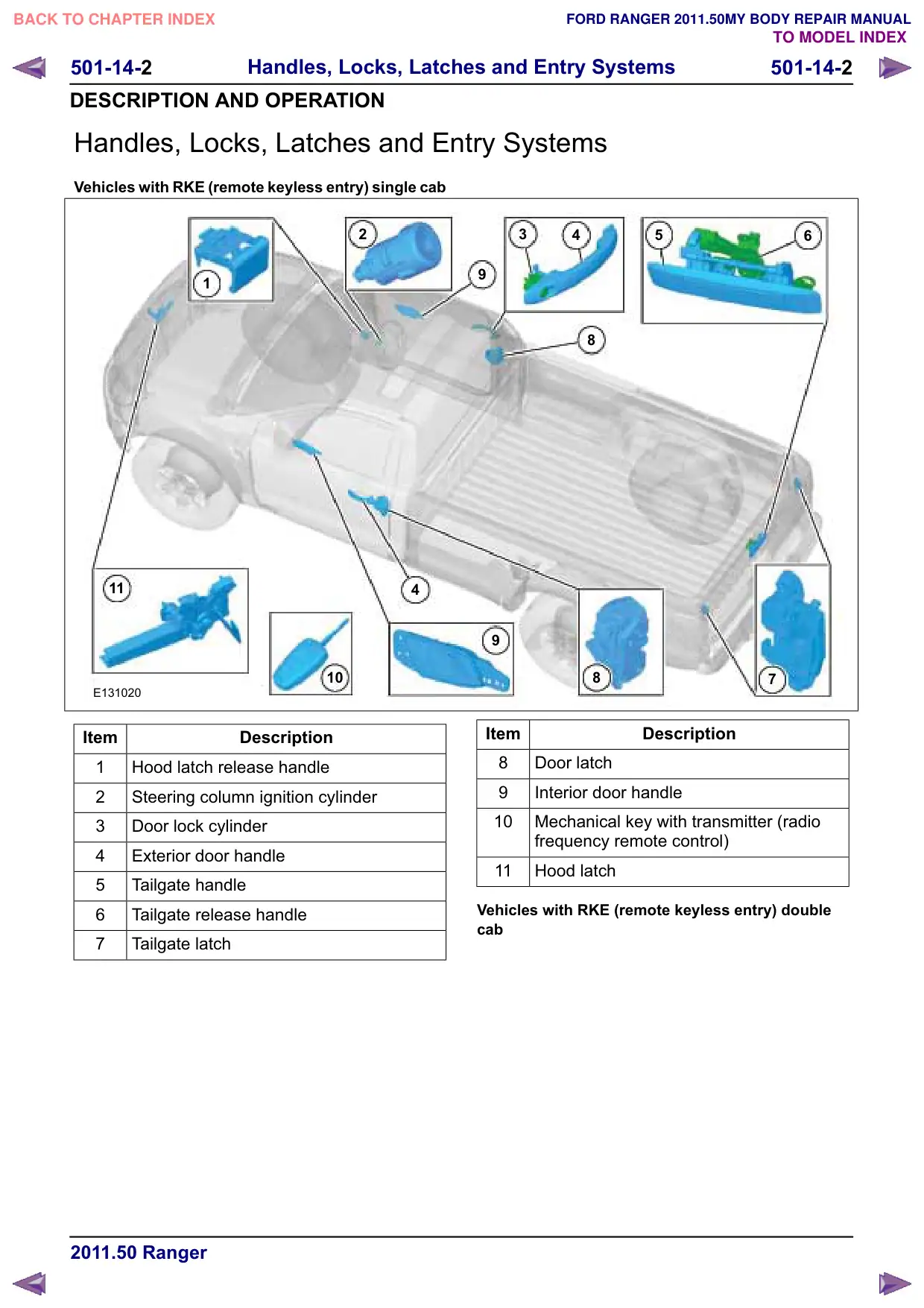
Door latch for single cab
The front door entry system contains a latch that
is fastened to the inside of the door frame and is
controlled by the exterior and interior door handles.
The latch contains the door ajar switch and door
lock actuator. The front doors are locked/unlocked
by the Remote Keyless Entry (RKE) transmitter,
lock/unlock button inside the vehicle or the driver
door lock cylinder.
The door latches have electric motors to operate
the locking and double locking function. The electric
motors are actuated directly by the BCM.
When the door latch is locked, the exterior door
handle is disengaged from the door latch.
A control switch is incorporated in the door latch
in the driver's door. This control switch monitors
the position of the door latch and reports the
information to the BCM. This information is sent to
the BCM for use in warning systems, locking
functions and anti-theft alarm systems.
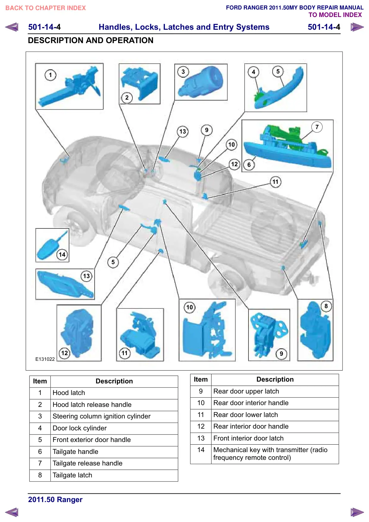
Door latch for double cab
The front door entry system contains a latch that
is fastened to the inside of the door frame and is
controlled by the exterior and interior door handles.
The latch contains the door ajar switch and door
lock actuator. The front doors are locked/unlocked
by the Remote Keyless Entry (RKE) transmitter,
lock/unlock button inside the vehicle or the driver
door lock cylinder.
The rear door entry system contains a latch that is
fastened to the inside of the door frame and is
controlled by the exterior and interior door handles.
The latch contains the door ajar switch and door
lock actuator. The rear doors can be
locked/unlocked by the RKE transmitter,
lock/unlock button inside the vehicle. The rear
doors have a child safety lock feature, which is a
manual lock on the inside of the rear door frame.
When the child safety feature is on, the rear doors
cannot be opened from the interior door handle.
The door latches have electric motors to operate
the locking and double locking function. The electric
motors are actuated directly by the BCM.
When the door latch is locked, the exterior door
handle is disengaged from the door latch.
A control switch is incorporated in the driver's door
latch. This control switch monitors the position of
the door latch and reports the information to the
BCM. This information is sent to the BCM for use
in warning systems, locking functions and anti-theft
alarm systems.
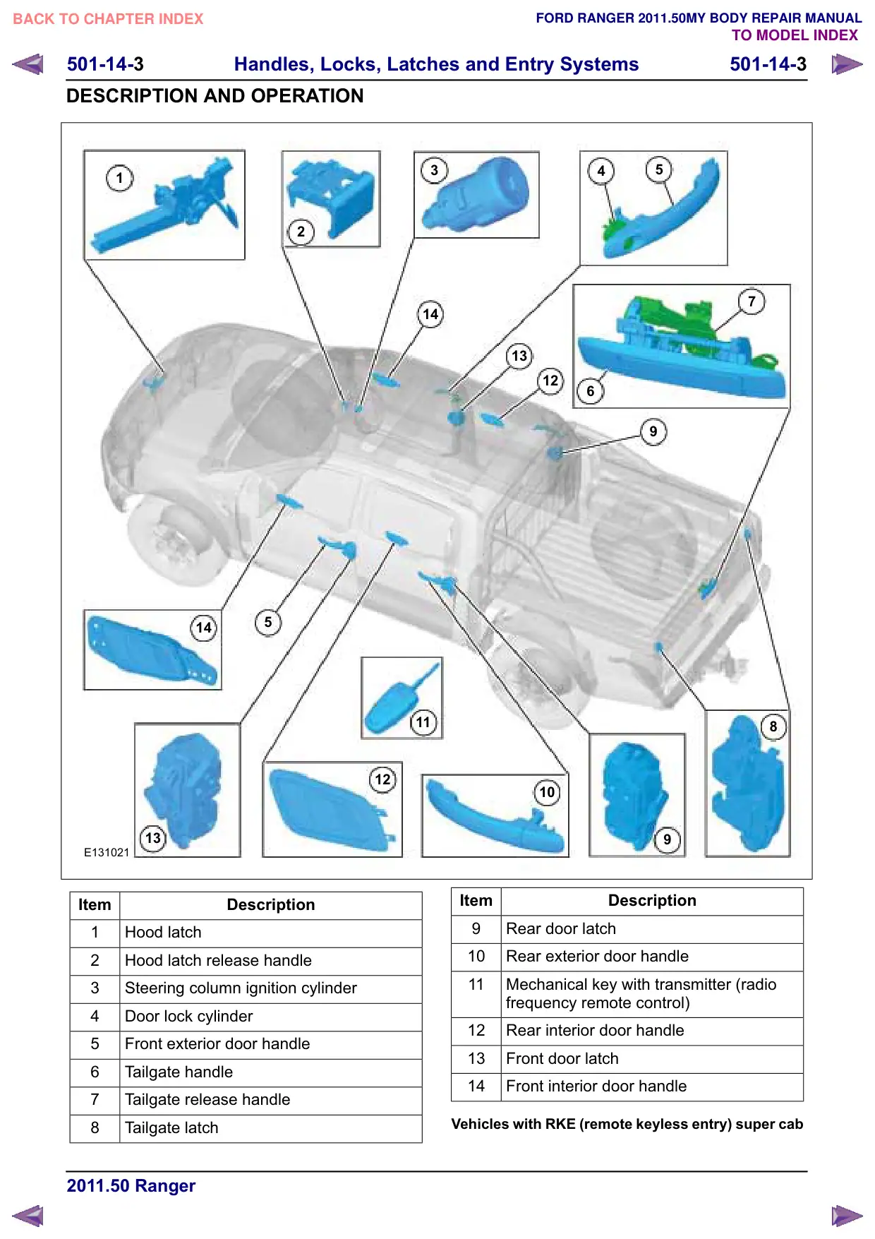
Door latch for super cab
The front door entry system contains a latch that
is fastened to the inside of the door frame and is
controlled by the exterior and interior door handles.
501-14-6
Handles, Locks, Latches and Entry Systems
501-14-6
DESCRIPTION AND OPERATION
The latch contains the door ajar switch and door
lock actuator. The front doors are locked/unlocked
by the Remote Keyless Entry (RKE) transmitter,
lock/unlock button inside the vehicle or the driver
door lock cylinder.
The front door latches have electric motors to
operate the locking and double locking function.
The electric motors are actuated directly by the
BCM.
When the front door latch is locked, the exterior
door handle is disengaged from the door latch.
A control switch is incorporated in the driver's door
latch. This control switch monitors the position of
the door latch and reports the information to the
BCM. This information is sent to the BCM for use
in warning systems, locking functions and anti-theft
alarm systems.
The rear door entry system contains a latch that is
fastened to the inside of the door frame and is
controlled by the exterior and interior door handles.
The latch contains the door ajar switch . No lock
actuators or mechanisms are fitted to the rear
doors, as the front door must be open in order to
access the rear door latch.
Tailgate latch
The lock cylinder is optional. If equipped, the
tailgate release handle is integrated with a lock
cylinder. The tailgate is not linked to the central
locking system.
Hood Latch
The hood latch system contains a latch fastened
to the body and a hood latch striker attached to the
hood. The latch is controlled by the hood latch
release handle and cable.
501-14-7
Handles, Locks, Latches and Entry Systems
501-14-7
GENERAL PROCEDURES
Remote Keyless Entry (RKE) Transmitter Programming
Programming
1. To programme new remote controls turn the
ignition key to position II four times within six
seconds.
2. Turn the ignition to position 0. A tone sounds to
indicate that it is now possible to programme
the remote controls for ten seconds.
3. Press any button on a new remote control. A
tone will sound as confirmation.
4. Repeat this last step for all your remote controls,
including your original. Do not remove the key
from the ignition when pressing the button on
this remote control.
5. Switch the ignition back on (position II) or wait
for ten seconds without programming another
remote control to end the key programming.
Only the remote controls which you have just
programmed are now able to lock and unlock
the vehicle.
501-14-8
Handles, Locks, Latches and Entry Systems
501-14-8
REMOVAL AND INSTALLATION
Ignition Lock Cylinder
General Equipment
Punch
Removal
NOTE: Removal steps in this procedure may
contain installation details.
1. Refer to: Passive Anti-Theft System (PATS)
Transceiver (419-01 Anti-Theft - Passive,
Removal and Installation).
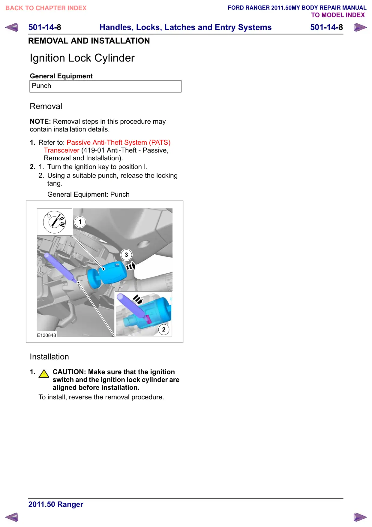
2.
1.
Turn the ignition key to position I.
2. Using a suitable punch, release the locking
tang.
General Equipment: Punch
1
3
2
E130848
Installation
1.
CAUTION: Make sure that the ignition
switch and the ignition lock cylinder are
aligned before installation.
To install, reverse the removal procedure.
501-14-
Handles, Locks, Latches and Entry Systems
501-14-
REMOVAL AND INSTALLATION
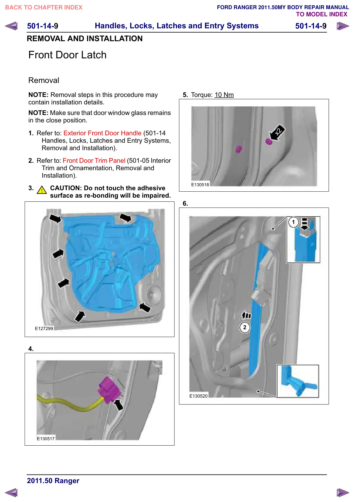
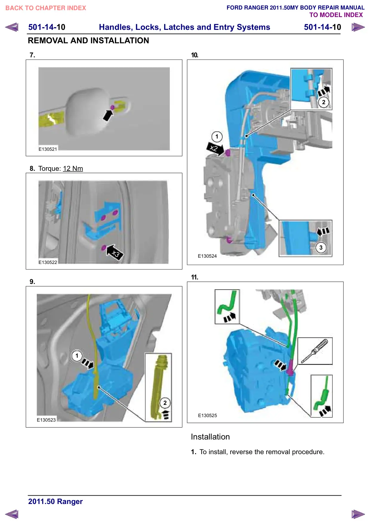
Front Door Latch
Removal
NOTE: Removal steps in this procedure may
contain installation details.
NOTE: Make sure that door window glass remains
in the close position.
1. Refer to: Exterior Front Door Handle (501-14
Handles, Locks, Latches and Entry Systems,
Removal and Installation).
2. Refer to: Front Door Trim Panel (501-05 Interior
Trim and Ornamentation, Removal and
Installation).
3.
CAUTION: Do not touch the adhesive
surface as re-bonding will be impaired.
E127299
4.
E130517
5. Torque: 10 Nm
x2
E130518
6.
1
2
E130520
501-14-11
Handles, Locks, Latches and Entry Systems
501-14-11
REMOVAL AND INSTALLATION
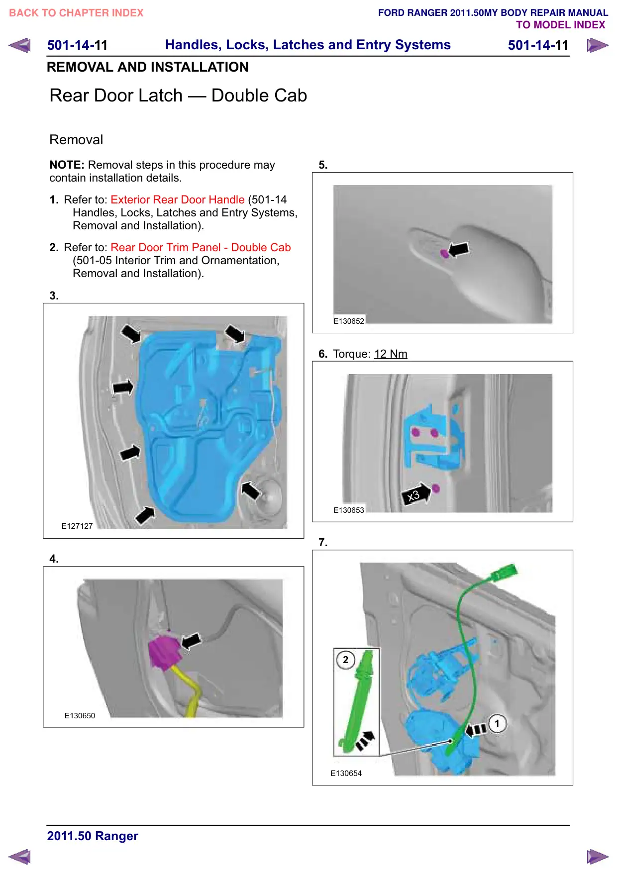
Rear Door Latch – Double Cab
Removal
NOTE: Removal steps in this procedure may
contain installation details.
1. Refer to: Exterior Rear Door Handle (501-14
Handles, Locks, Latches and Entry Systems,
Removal and Installation).
2. Refer to: Rear Door Trim Panel - Double Cab
(501-05 Interior Trim and Ornamentation,
Removal and Installation).
3.
E127127
4.
E130650
5.
E130652
6. Torque: 12 Nm
x3
E130653
7.
2
1
E130654
501-14-12
Handles, Locks, Latches and Entry Systems
501-14-12
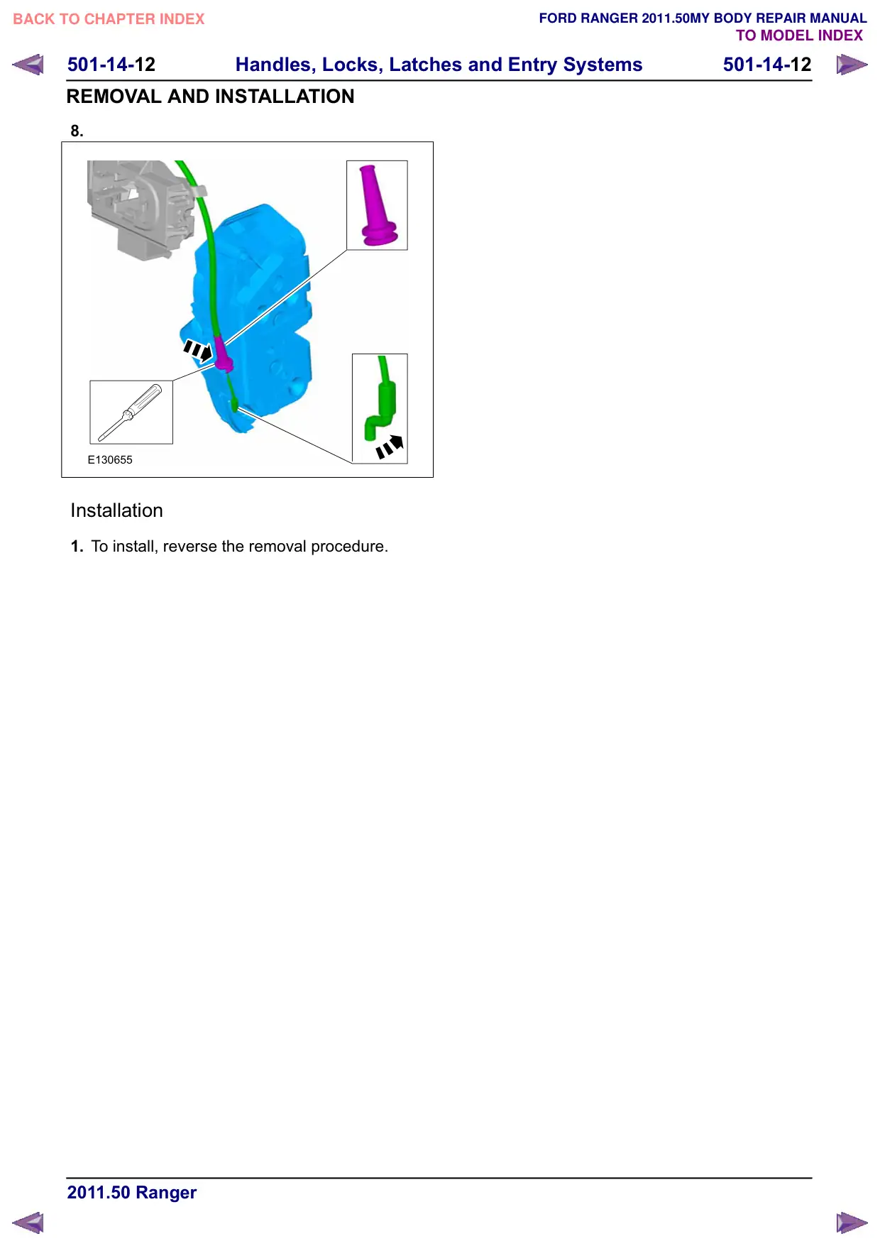
REMOVAL AND INSTALLATION
8.
E130655
Installation
1. To install, reverse the removal procedure.
501-14-13
Handles, Locks, Latches and Entry Systems
501-14-13
REMOVAL AND INSTALLATION
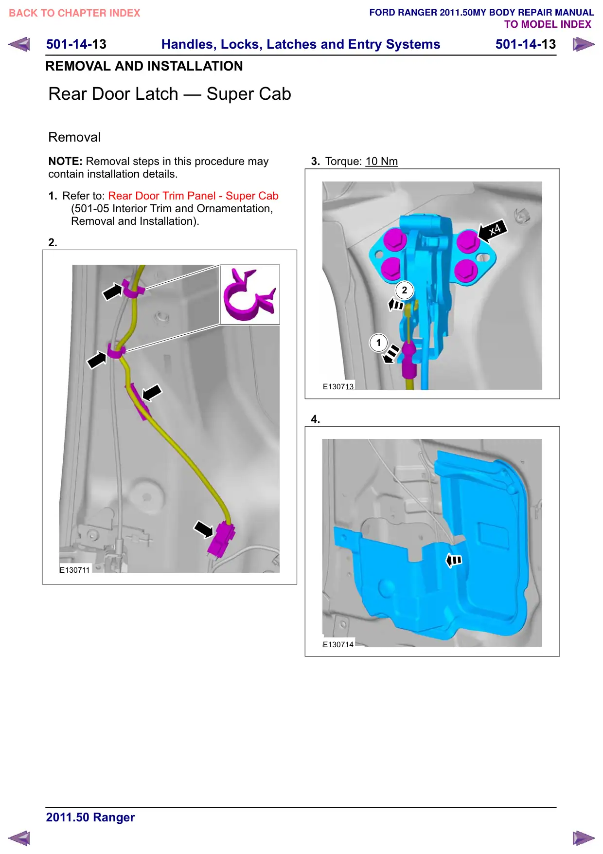
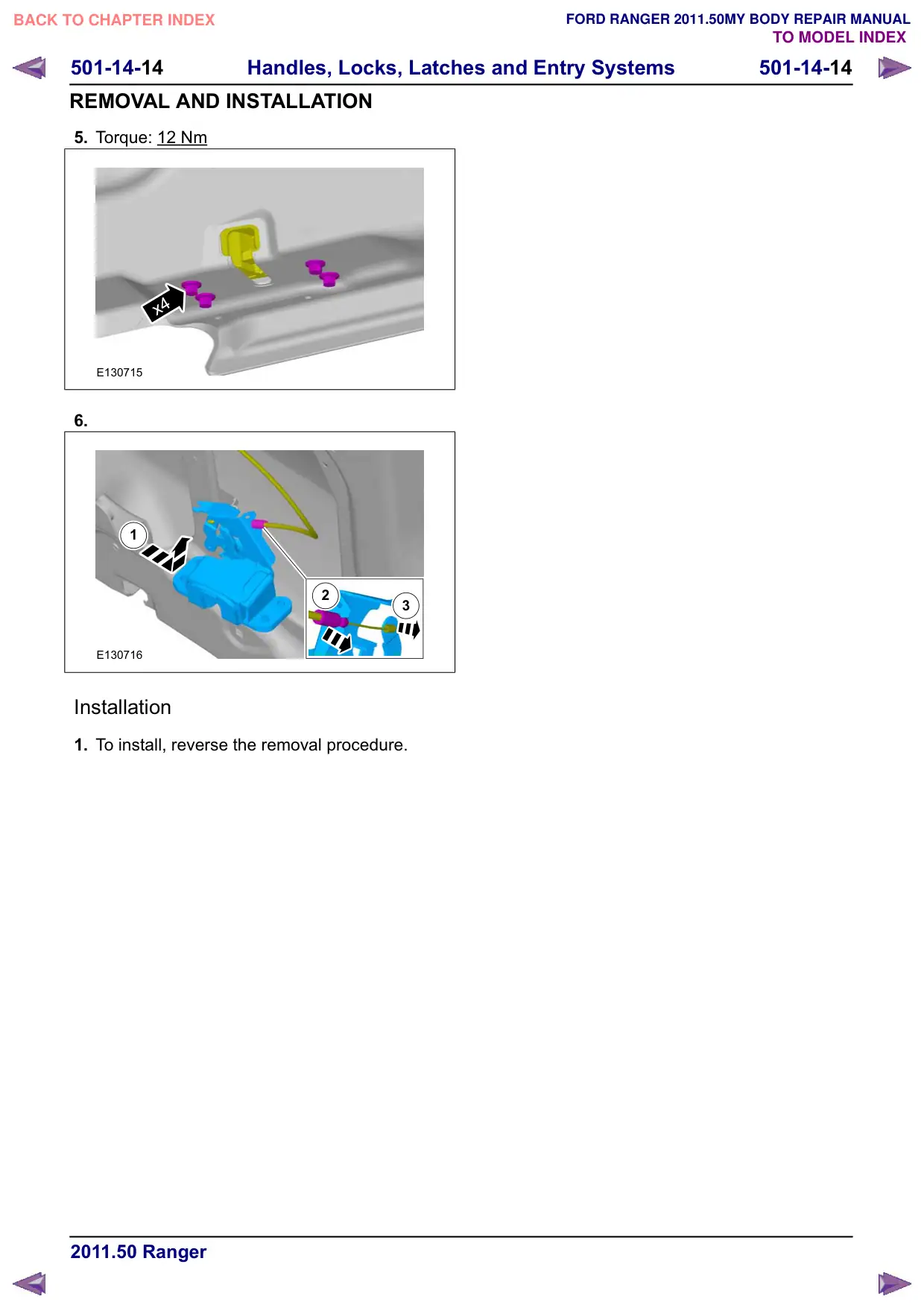
Rear Door Latch – Super Cab
Removal
NOTE: Removal steps in this procedure may
contain installation details.
1. Refer to: Rear Door Trim Panel - Super Cab
(501-05 Interior Trim and Ornamentation,
Removal and Installation).
2.
E130711
3. Torque: 10 Nm
x4
2
1
E130713
4.
E130714
501-14-15
Handles, Locks, Latches and Entry Systems
501-14-15
REMOVAL AND INSTALLATION
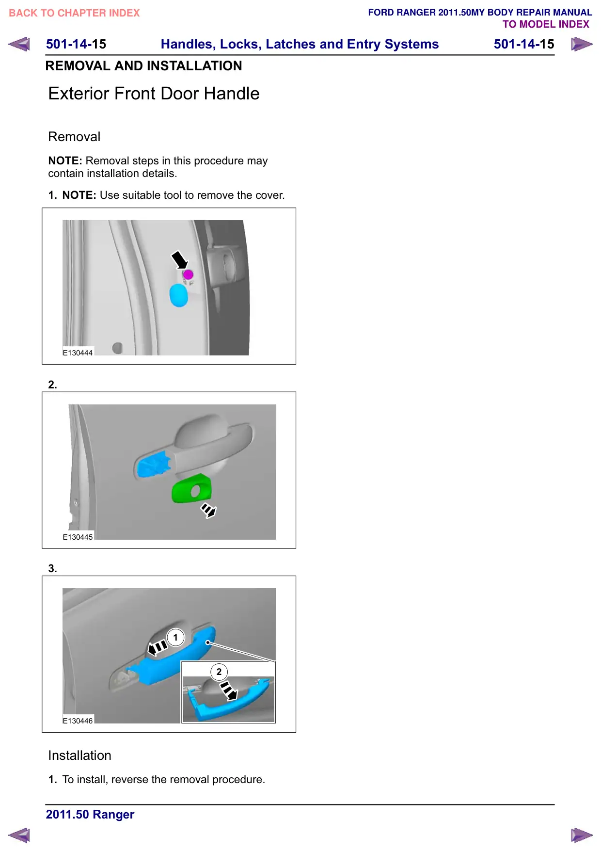
Exterior Front Door Handle
Removal
NOTE: Removal steps in this procedure may
contain installation details.
1. NOTE: Use suitable tool to remove the cover.
E130444
2.
E130445
3.
1
2
E130446
Installation
1. To install, reverse the removal procedure.
501-14-16
Handles, Locks, Latches and Entry Systems
501-14-16
REMOVAL AND INSTALLATION
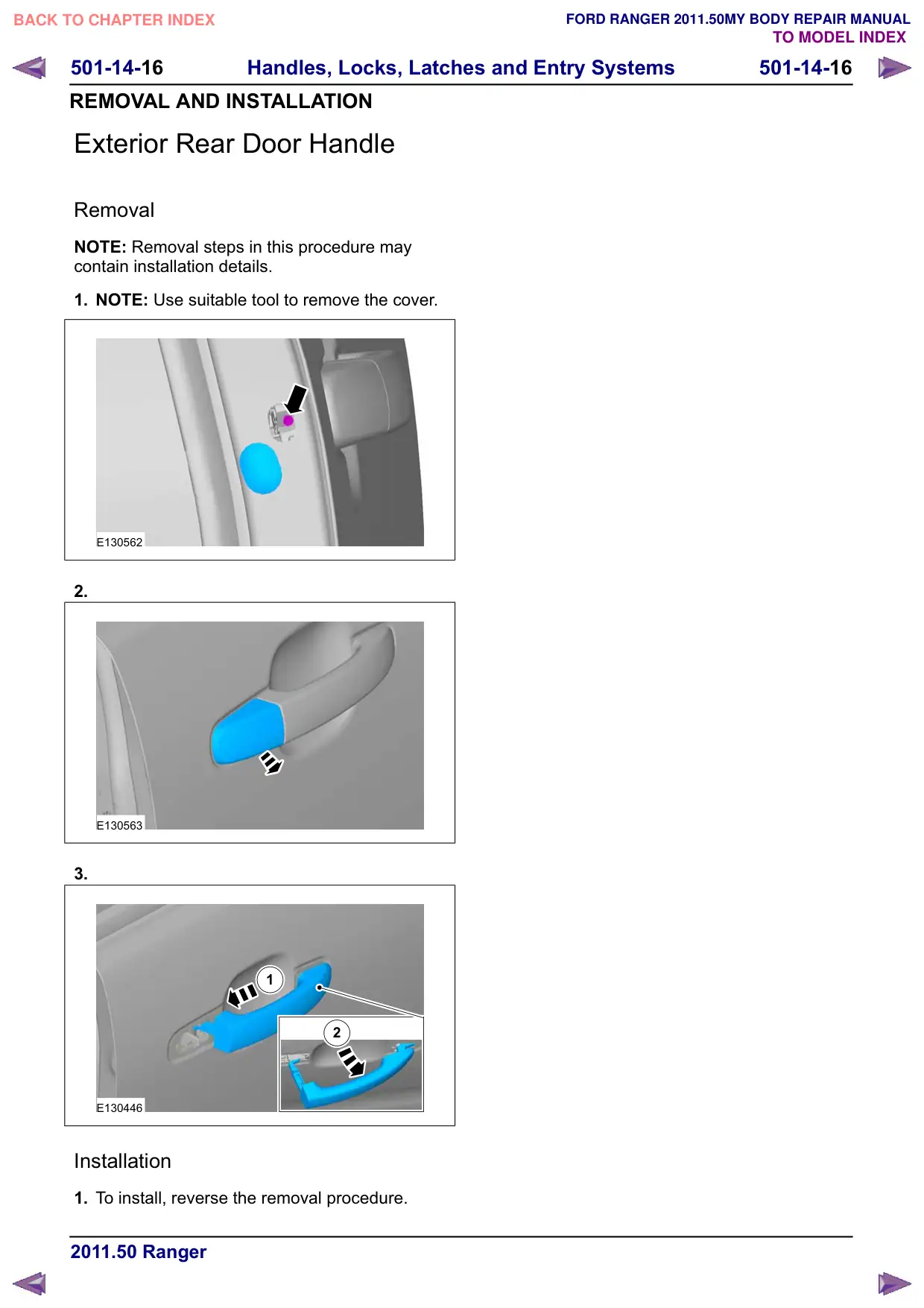
Exterior Rear Door Handle
Removal
NOTE: Removal steps in this procedure may
contain installation details.
1. NOTE: Use suitable tool to remove the cover.
E130562
2.
E130563
3.
1
2
E130446
Installation
1. To install, reverse the removal procedure.
501-14-17
Handles, Locks, Latches and Entry Systems
501-14-17
REMOVAL AND INSTALLATION
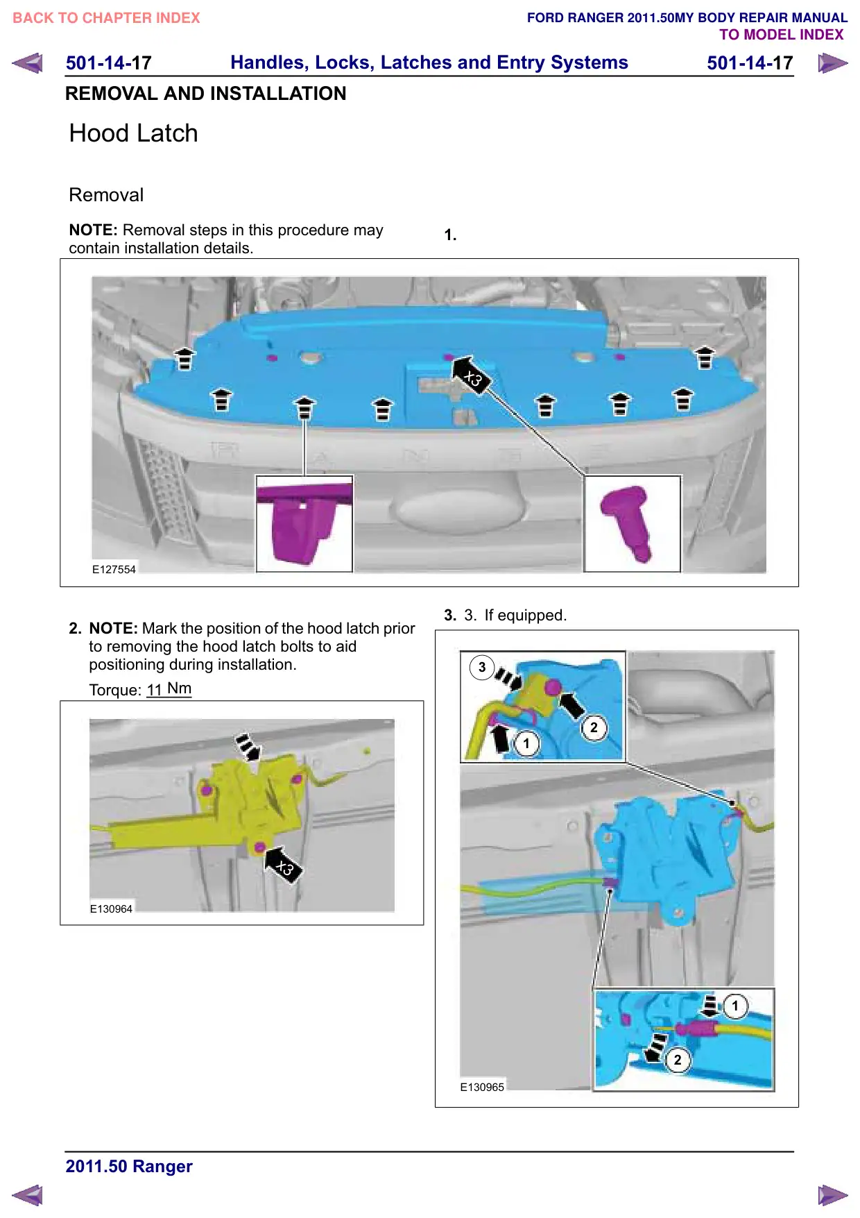
Hood Latch
Removal
NOTE: Removal steps in this procedure may
contain installation details.
E127554
2. NOTE: Mark the position of the hood latch prior
to removing the hood latch bolts to aid
positioning during installation.
Torque: 1
1
Nm
x3
E130964
1.
x3
3.
3.
If equipped.
3
2
1
1
2
E130965
501-14-18
Handles, Locks, Latches and Entry Systems
501-14-18
REMOVAL AND INSTALLATION
Installation
1.
CAUTION: Make sure that the clearance
on either side of the hood is equal and
no strain is placed on the hood latch.
NOTE: Check the latch adjustment to make sure
the latch was installed and aligned correctly.
To install, reverse the removal procedure.
501-14-21
Handles, Locks, Latches and Entry Systems
501-14-21
DISASSEMBLY AND ASSEMBLY
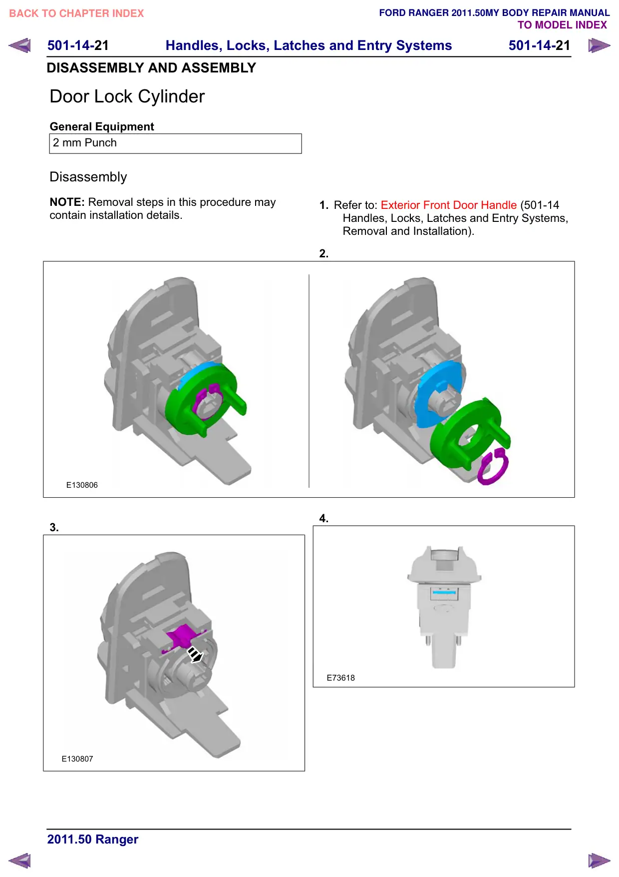
Door Lock Cylinder
General Equipment
2 mm Punch
Disassembly
NOTE: Removal steps in this procedure may
contain installation details.
E130806
3.
E130807
1. Refer to: Exterior Front Door Handle (501-14
Handles, Locks, Latches and Entry Systems,
Removal and Installation).
2.
4.
E73618
501-14-22
Handles, Locks, Latches and Entry Systems
501-14-22
DISASSEMBLY AND ASSEMBLY
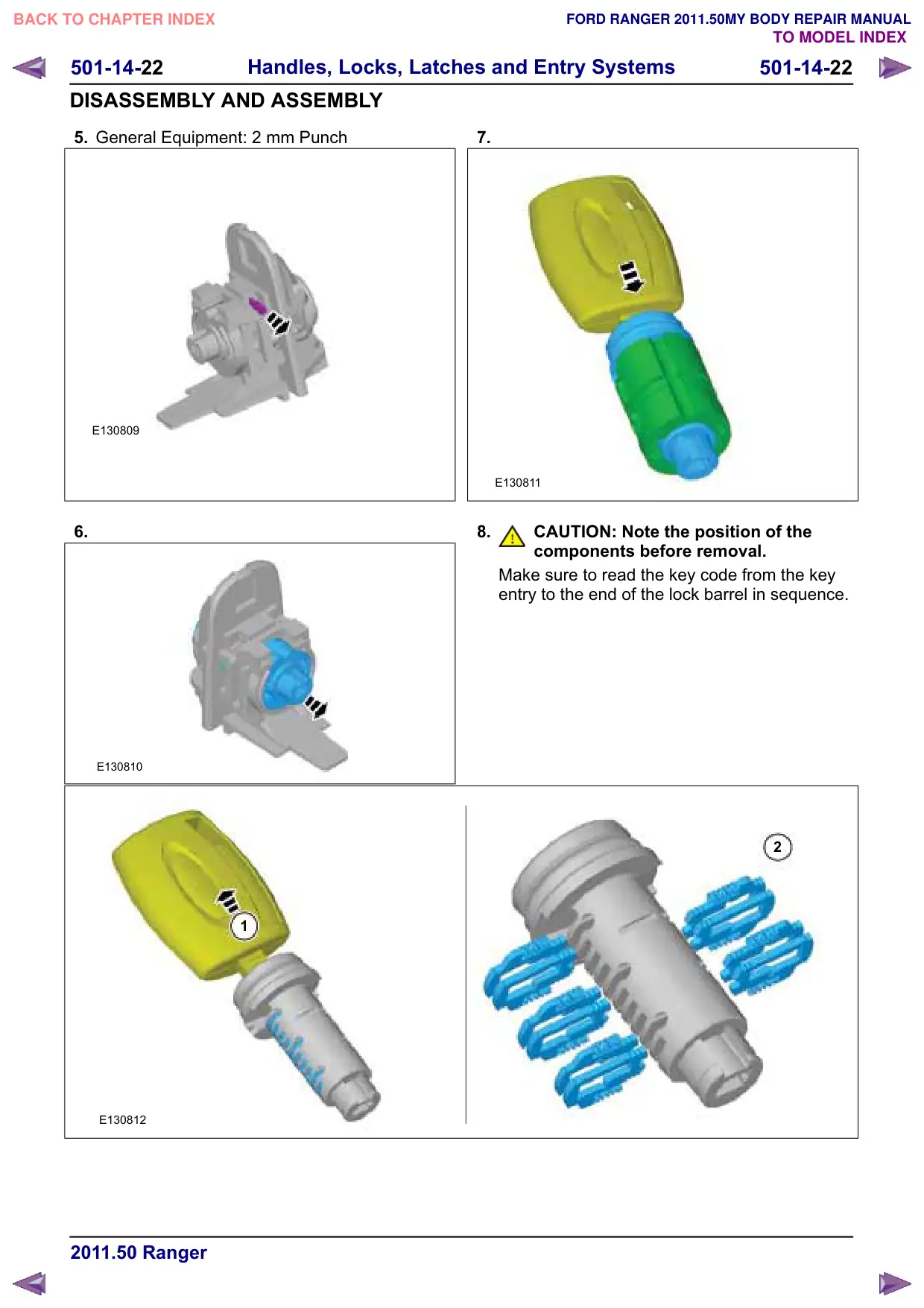
5. General Equipment: 2 mm Punch
E130809
6.
E130810
1
E130812
7.
E130811
8.
CAUTION: Note the position of the
components before removal.
Make sure to read the key code from the key
entry to the end of the lock barrel in sequence.
2
501-14-23
Handles, Locks, Latches and Entry Systems
501-14-23
DISASSEMBLY AND ASSEMBLY
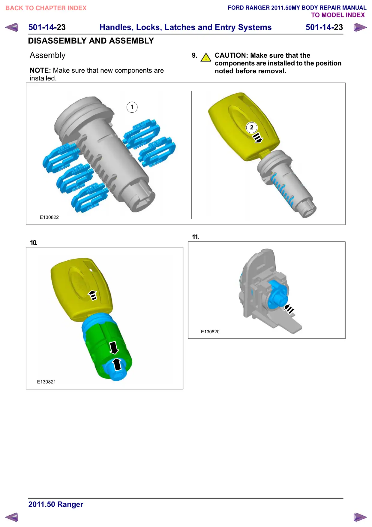
Assembly
NOTE: Make sure that new components are
installed.
1
E130822
10.
E130821
9.
CAUTION: Make sure that the
components are installed to the position
noted before removal.
2
11.
E130820
501-14-24
Handles, Locks, Latches and Entry Systems
501-14-24
DISASSEMBLY AND ASSEMBLY
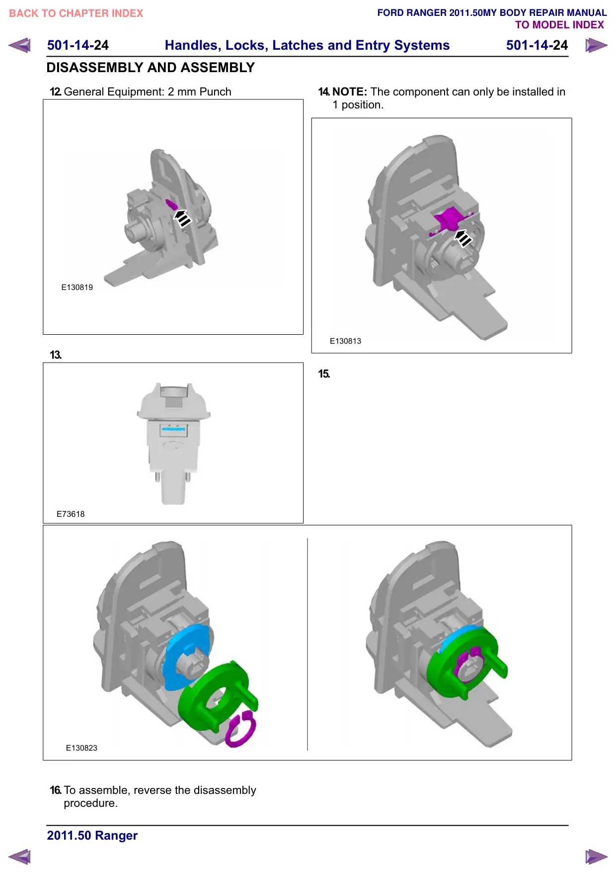
12.General Equipment: 2 mm Punch
E130819
13.
E73618
E130823
16.To assemble, reverse the disassembly
procedure.
14.NOTE: The component can only be installed in
1 position.
E130813
15.