419-10-3
Multifunction Electronic Modules
419-10-3
DESCRIPTION AND OPERATION
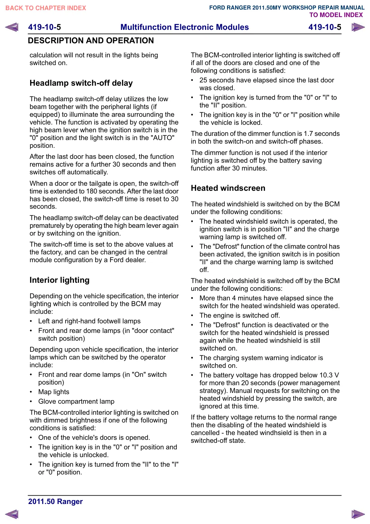
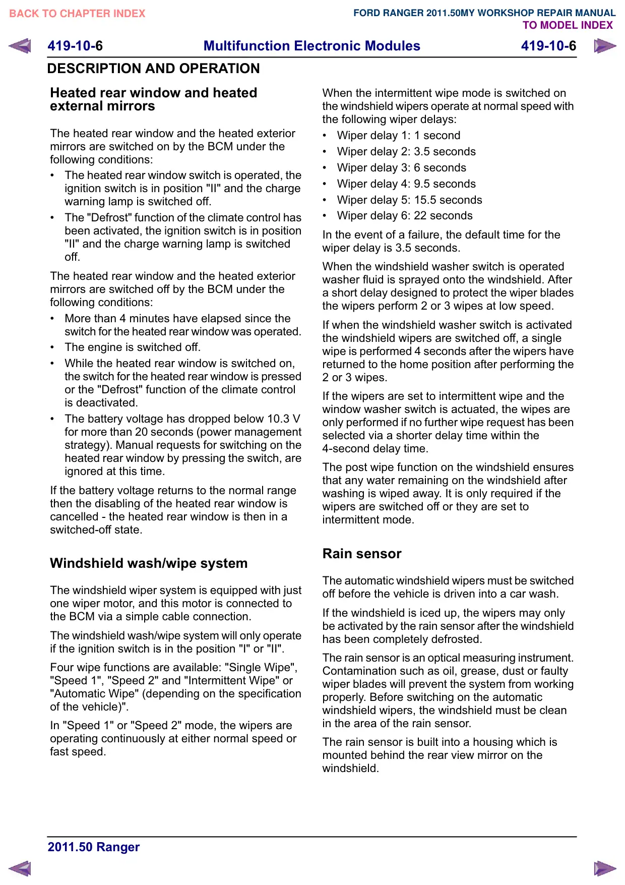
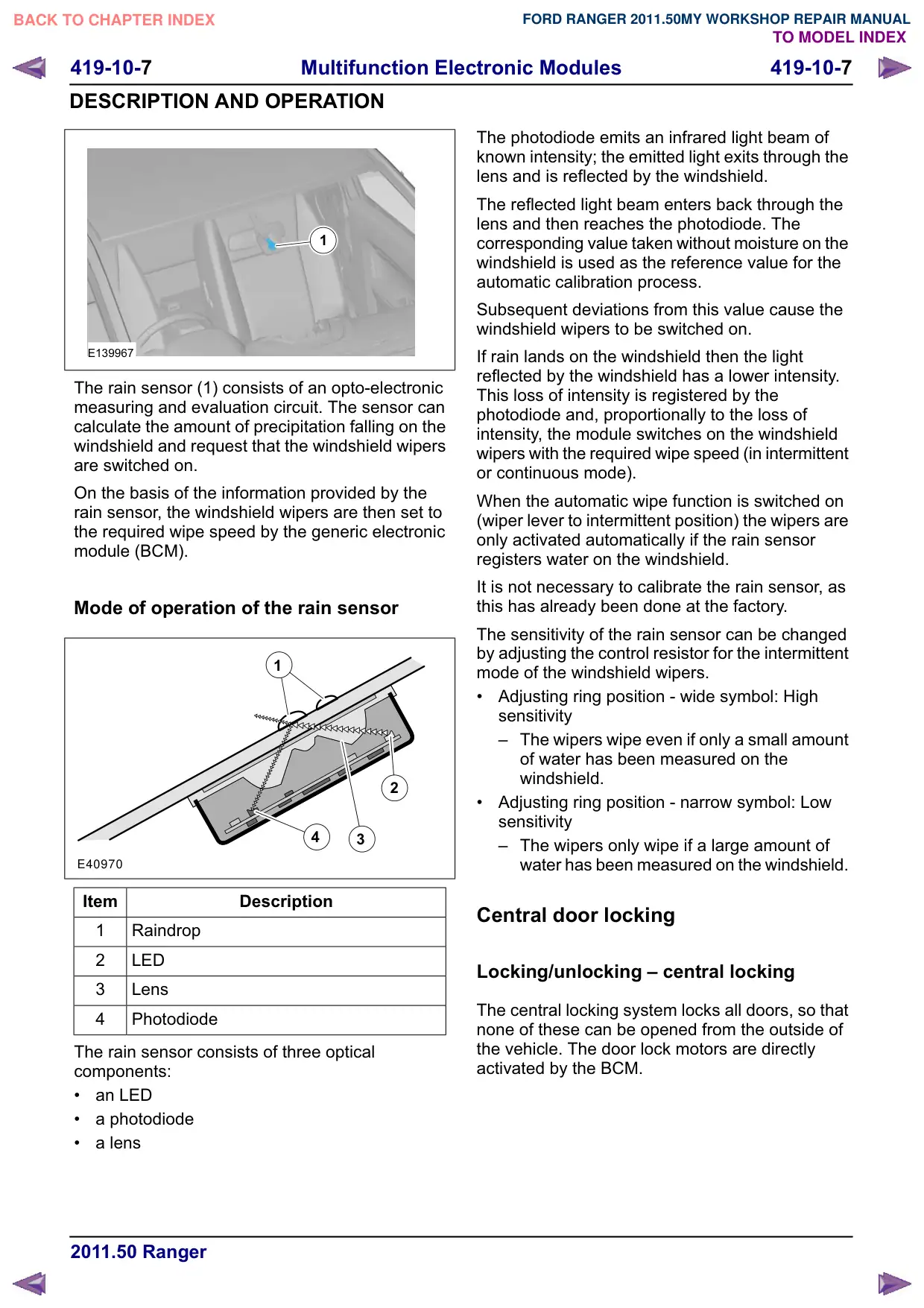
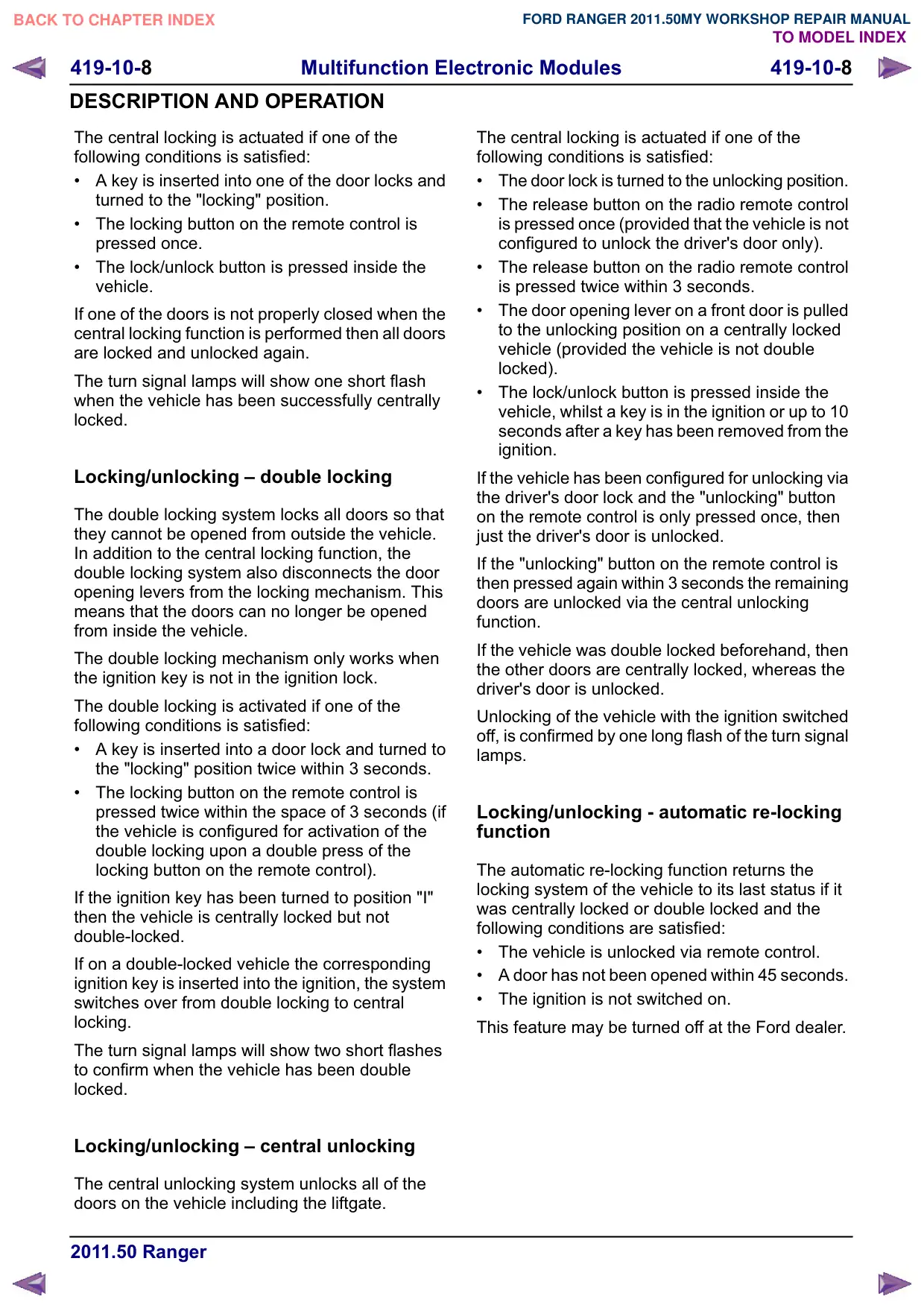
Item
Description
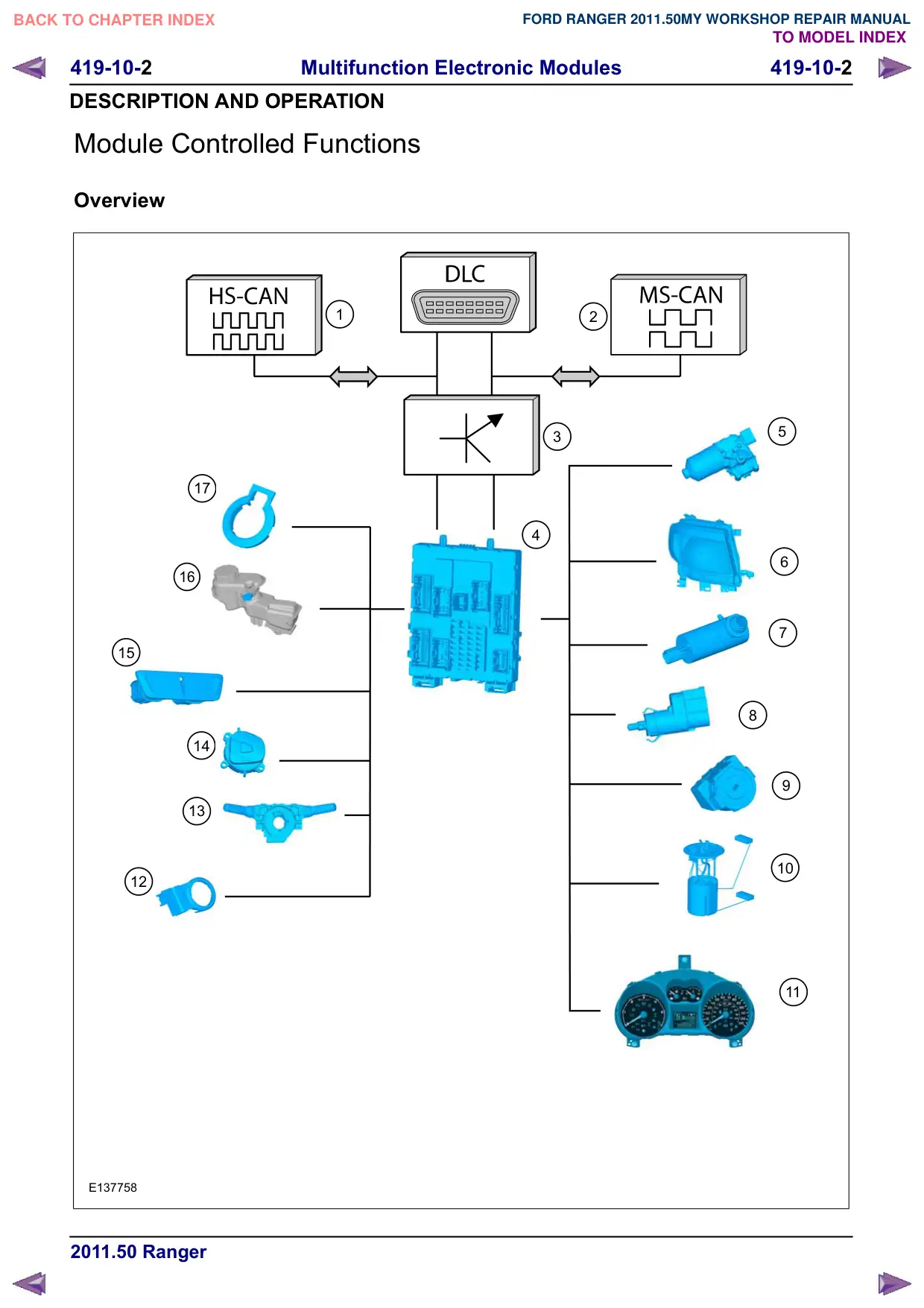
1
HS CAN bus
2
MS CAN bus
3
Gateway (BCM)
4
%&0
5
Front window wiper motors
6
Headlamp
7
Window washer pump
8
Stoplamp switch
Ignition lock
10
Fuel level sensor
11
Instrument cluster
12
PATS transceiver (vehicles without
keyless vehicle module only)
13
Multifunction switch
14
Speed control switch
15
Hazard flasher switch
16
Brake fluid level switch
17
Light/rain sensor
Body control module (BCM)
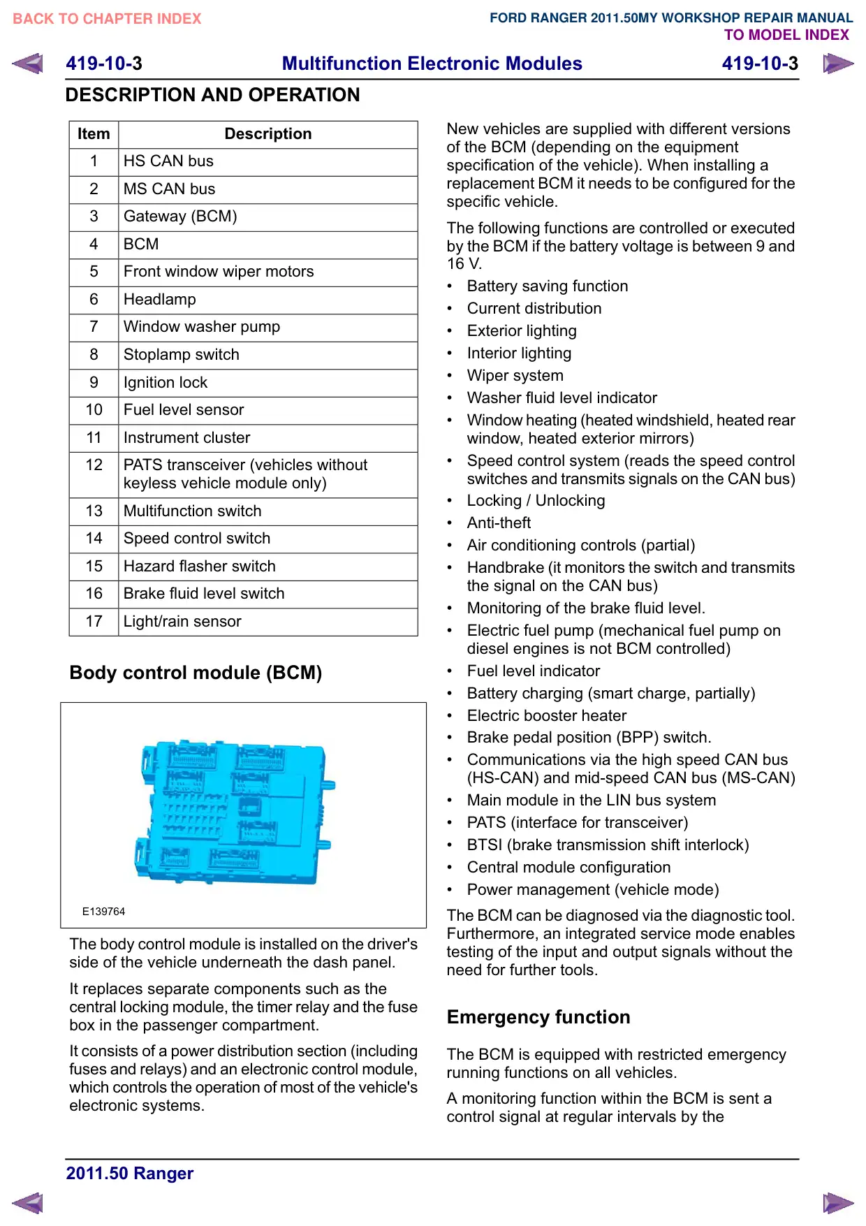
E139764
The body control module is installed on the driver's
side of the vehicle underneath the dash panel.
It replaces separate components such as the
central locking module, the timer relay and the fuse
box in the passenger compartment.
It consists of a power distribution section (including
fuses and relays) and an electronic control module,
which controls the operation of most of the vehicle's
electronic systems.
New vehicles are supplied with different versions
of the BCM (depending on the equipment
specification of the vehicle). When installing a
replacement BCM it needs to be configured for the
specific vehicle.
The following functions are controlled or executed
by the BCM if the battery voltage is between 9 and
16 V.
Battery saving function
Current distribution
Exterior lighting
Interior lighting
Wiper system
Washer fluid level indicator
Window heating (heated windshield, heated rear
window, heated exterior mirrors)
Speed control system (reads the speed control
switches and transmits signals on the CAN bus)
Locking / Unlocking
Anti-theft
Air conditioning controls (partial)
Handbrake (it monitors the switch and transmits
the signal on the CAN bus)
Monitoring of the brake fluid level.
Electric fuel pump (mechanical fuel pump on
diesel engines is not BCM controlled)
Fuel level indicator
Battery charging (smart charge, partially)
Electric booster heater
Brake pedal position (BPP) switch.
Communications via the high speed CAN bus
(HS-CAN) and mid-speed CAN bus (MS-CAN)
Main module in the LIN bus system
PATS (interface for transceiver)
BTSI (brake transmission shift interlock)
Central module configuration
Power management (vehicle mode)
The BCM can be diagnosed via the diagnostic tool.
Furthermore, an integrated service mode enables
testing of the input and output signals without the
need for further tools.
Emergency function
The BCM is equipped with restricted emergency
running functions on all vehicles.
A monitoring function within the BCM is sent a
control signal at regular intervals by the
419-10-4
Multifunction Electronic Modules
419-10-4
DESCRIPTION AND OPERATION
microcontroller. If this control signal is not sent, the
BCM goes into emergency running mode after a
specified time.
In this case, vehicle electrical functions will be
restricted to the following:
Stop light will function normally.
Horn will function normally.
Dipped beam and position lamps will be
switched on permanently, irrespective of light
switch position.
Windscreen wipers will perform continuous
wiping at normal wipe speed, irrespective of
wiper switch position.
The emergency running mode is switched off when
the ignition is switched to "0". When the ignition is
switched on again, the BCM will try to recover. If
recovery fails, the vehicle cannot be started.
Light switch
If the ignition lock is in position "0" for more than 3
minutes then the front fog lamps, rear fog lamp
and the main beam headlamps are deactivated
when the ignition is next switched on (if they were
previously activated).
Combined rain sensor/light sensor
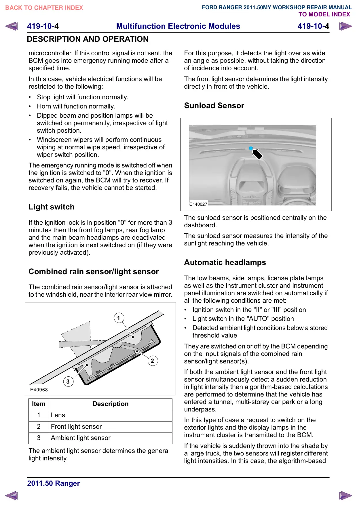
The combined rain sensor/light sensor is attached
to the windshield, near the interior rear view mirror.
1
2
3
E40968
Item
Description
1
Lens
2
Front light sensor
3
Ambient light sensor
The ambient light sensor determines the general
light intensity.
For this purpose, it detects the light over as wide
an angle as possible, without taking the direction
of incidence into account.
The front light sensor determines the light intensity
directly in front of the vehicle.
Sunload Sensor
E140027
The sunload sensor is positioned centrally on the
dashboard.
The sunload sensor measures the intensity of the
sunlight reaching the vehicle.
Automatic headlamps
The low beams, side lamps, license plate lamps
as well as the instrument cluster and instrument
panel illumination are switched on automatically if
all the following conditions are met:
Ignition switch in the "II" or "III" position
Light switch in the "AUTO" position
Detected ambient light conditions below a stored
threshold value
They are switched on or off by the BCM depending
on the input signals of the combined rain
sensor/light sensor(s).
If both the ambient light sensor and the front light
sensor simultaneously detect a sudden reduction
in light intensity then algorithm-based calculations
are performed to determine that the vehicle has
entered a tunnel, multi-storey car park or a long
underpass.
In this type of case a request to switch on the
exterior lights and the display lamps in the
instrument cluster is transmitted to the BCM.
If the vehicle is suddenly thrown into the shade by
a large truck, the two sensors will register different
light intensities. In this case, the algorithm-based
419-10-5
Multifunction Electronic Modules
419-10-5
DESCRIPTION AND OPERATION
calculation will not result in the lights being
switched on.
Headlamp switch-off delay
The headlamp switch-off delay utilizes the low
beam together with the peripheral lights (if
equipped) to illuminate the area surrounding the
vehicle. The function is activated by operating the
high beam lever when the ignition switch is in the
"0" position and the light switch is in the "AUTO"
position.
After the last door has been closed, the function
remains active for a further 30 seconds and then
switches off automatically.
When a door or the tailgate is open, the switch-off
time is extended to 180 seconds. After the last door
has been closed, the switch-off time is reset to 30
seconds.
The headlamp switch-off delay can be deactivated
prematurely by operating the high beam lever again
or by switching on the ignition.
The switch-off time is set to the above values at
the factory, and can be changed in the central
module configuration by a Ford dealer.
Interior lighting
Depending on the vehicle specification, the interior
lighting which is controlled by the BCM may
include:
Left and right-hand footwell lamps
Front and rear dome lamps (in "door contact"
switch position)
Depending upon vehicle specification, the interior
lamps which can be switched by the operator
include:
Front and rear dome lamps (in "On" switch
position)
Map lights
Glove compartment lamp
The BCM-controlled interior lighting is switched on
with dimmed brightness if one of the following
conditions is satisfied:
One of the vehicle's doors is opened.
The ignition key is in the "0" or "I" position and
the vehicle is unlocked.
The ignition key is turned from the "II" to the "I"
or "0" position.
The BCM-controlled interior lighting is switched off
if all of the doors are closed and one of the
following conditions is satisfied:
25 seconds have elapsed since the last door
was closed.
The ignition key is turned from the "0" or "I" to
the "II" position.
The ignition key is in the "0" or "I" position while
the vehicle is locked.
The duration of the dimmer function is 1.7 seconds
in both the switch-on and switch-off phases.
The dimmer function is not used if the interior
lighting is switched off by the battery saving
function after 30 minutes.
Heated windscreen
The heated windshield is switched on by the BCM
under the following conditions:
The heated windshield switch is operated, the
ignition switch is in position "II" and the charge
warning lamp is switched off.
The "Defrost" function of the climate control has
been activated, the ignition switch is in position
"II" and the charge warning lamp is switched
off.
The heated windshield is switched off by the BCM
under the following conditions:
More than 4 minutes have elapsed since the
switch for the heated windshield was operated.
The engine is switched off.
The "Defrost" function is deactivated or the
switch for the heated windshield is pressed
again while the heated windshield is still
switched on.
The charging system warning indicator is
switched on.
The battery voltage has dropped below 10.3 V
for more than 20 seconds (power management
strategy). Manual requests for switching on the
heated windshield by pressing the switch, are
ignored at this time.
If the battery voltage returns to the normal range
then the disabling of the heated windshield is
cancelled - the heated windhsield is then in a
switched-off state.
419-10-6
Multifunction Electronic Modules
419-10-6
DESCRIPTION AND OPERATION
Heated rear window and heated
external mirrors
The heated rear window and the heated exterior
mirrors are switched on by the BCM under the
following conditions:
The heated rear window switch is operated, the
ignition switch is in position "II" and the charge
warning lamp is switched off.
The "Defrost" function of the climate control has
been activated, the ignition switch is in position
"II" and the charge warning lamp is switched
off.
The heated rear window and the heated exterior
mirrors are switched off by the BCM under the
following conditions:
More than 4 minutes have elapsed since the
switch for the heated rear window was operated.
The engine is switched off.
While the heated rear window is switched on,
the switch for the heated rear window is pressed
or the "Defrost" function of the climate control
is deactivated.
The battery voltage has dropped below 10.3 V
for more than 20 seconds (power management
strategy). Manual requests for switching on the
heated rear window by pressing the switch, are
ignored at this time.
If the battery voltage returns to the normal range
then the disabling of the heated rear window is
cancelled - the heated rear window is then in a
switched-off state.
Windshield wash/wipe system
The windshield wiper system is equipped with just
one wiper motor, and this motor is connected to
the BCM via a simple cable connection.
The windshield wash/wipe system will only operate
if the ignition switch is in the position "I" or "II".
Four wipe functions are available: "Single Wipe",
"Speed 1", "Speed 2" and "Intermittent Wipe" or
"Automatic Wipe" (depending on the specification
of the vehicle)".
In "Speed 1" or "Speed 2" mode, the wipers are
operating continuously at either normal speed or
fast speed.
When the intermittent wipe mode is switched on
the windshield wipers operate at normal speed with
the following wiper delays:
Wiper delay 1: 1 second
Wiper delay 2: 3.5 seconds
Wiper delay 3: 6 seconds
Wiper delay 4: 9.5 seconds
Wiper delay 5: 15.5 seconds
Wiper delay 6: 22 seconds
In the event of a failure, the default time for the
wiper delay is 3.5 seconds.
When the windshield washer switch is operated
washer fluid is sprayed onto the windshield. After
a short delay designed to protect the wiper blades
the wipers perform 2 or 3 wipes at low speed.
If when the windshield washer switch is activated
the windshield wipers are switched off, a single
wipe is performed 4 seconds after the wipers have
returned to the home position after performing the
2 or 3 wipes.
If the wipers are set to intermittent wipe and the
window washer switch is actuated, the wipes are
only performed if no further wipe request has been
selected via a shorter delay time within the
4-second delay time.
The post wipe function on the windshield ensures
that any water remaining on the windshield after
washing is wiped away. It is only required if the
wipers are switched off or they are set to
intermittent mode.
Rain sensor
The automatic windshield wipers must be switched
off before the vehicle is driven into a car wash.
If the windshield is iced up, the wipers may only
be activated by the rain sensor after the windshield
has been completely defrosted.
The rain sensor is an optical measuring instrument.
Contamination such as oil, grease, dust or faulty
wiper blades will prevent the system from working
properly. Before switching on the automatic
windshield wipers, the windshield must be clean
in the area of the rain sensor.
The rain sensor is built into a housing which is
mounted behind the rear view mirror on the
windshield.
419-10-7
Multifunction Electronic Modules
419-10-7
DESCRIPTION AND OPERATION
1
E139967
The rain sensor (1) consists of an opto-electronic
measuring and evaluation circuit. The sensor can
calculate the amount of precipitation falling on the
windshield and request that the windshield wipers
are switched on.
On the basis of the information provided by the
rain sensor, the windshield wipers are then set to
the required wipe speed by the generic electronic
module (BCM).
Mode of operation of the rain sensor
1
2
4
3
E40970
Item
Description
1
Raindrop
2
LED
3
Lens
4
Photodiode
The rain sensor consists of three optical
components:
an LED
D SKRWRGLRGH
a lens
The photodiode emits an infrared light beam of
known intensity; the emitted light exits through the
lens and is reflected by the windshield.
The reflected light beam enters back through the
lens and then reaches the photodiode. The
corresponding value taken without moisture on the
windshield is used as the reference value for the
automatic calibration process.
Subsequent deviations from this value cause the
windshield wipers to be switched on.
If rain lands on the windshield then the light
reflected by the windshield has a lower intensity.
This loss of intensity is registered by the
photodiode and, proportionally to the loss of
intensity, the module switches on the windshield
wipers with the required wipe speed (in intermittent
or continuous mode).
When the automatic wipe function is switched on
(wiper lever to intermittent position) the wipers are
only activated automatically if the rain sensor
registers water on the windshield.
It is not necessary to calibrate the rain sensor, as
this has already been done at the factory.
The sensitivity of the rain sensor can be changed
by adjusting the control resistor for the intermittent
mode of the windshield wipers.
Adjusting ring position - wide symbol: High
sensitivity
œ The wipers wipe even if only a small amount
of water has been measured on the
windshield.
Adjusting ring position - narrow symbol: Low
sensitivity
œ The wipers only wipe if a large amount of
water has been measured on the windshield.
Central door locking
Locking/unlocking œ central locking
The central locking system locks all doors, so that
none of these can be opened from the outside of
the vehicle. The door lock motors are directly
activated by the BCM.
419-10-8
Multifunction Electronic Modules
419-10-8
DESCRIPTION AND OPERATION
The central locking is actuated if one of the
following conditions is satisfied:
A key is inserted into one of the door locks and
turned to the "locking" position.
The locking button on the remote control is
pressed once.
The lock/unlock button is pressed inside the
vehicle.
If one of the doors is not properly closed when the
central locking function is performed then all doors
are locked and unlocked again.
The turn signal lamps will show one short flash
when the vehicle has been successfully centrally
locked.
Locking/unlocking œ double locking
The double locking system locks all doors so that
they cannot be opened from outside the vehicle.
In addition to the central locking function, the
double locking system also disconnects the door
opening levers from the locking mechanism. This
means that the doors can no longer be opened
from inside the vehicle.
The double locking mechanism only works when
the ignition key is not in the ignition lock.
The double locking is activated if one of the
following conditions is satisfied:
A key is inserted into a door lock and turned to
the "locking" position twice within 3 seconds.
The locking button on the remote control is
pressed twice within the space of 3 seconds (if
the vehicle is configured for activation of the
double locking upon a double press of the
locking button on the remote control).
If the ignition key has been turned to position "I"
then the vehicle is centrally locked but not
double-locked.
If on a double-locked vehicle the corresponding
ignition key is inserted into the ignition, the system
switches over from double locking to central
locking.
The turn signal lamps will show two short flashes
to confirm when the vehicle has been double
locked.
Locking/unlocking œ central unlocking
The central unlocking system unlocks all of the
doors on the vehicle including the liftgate.
The central locking is actuated if one of the
following conditions is satisfied:
The door lock is turned to the unlocking position.
The release button on the radio remote control
is pressed once (provided that the vehicle is not
configured to unlock the driver's door only).
The release button on the radio remote control
is pressed twice within 3 seconds.
The door opening lever on a front door is pulled
to the unlocking position on a centrally locked
vehicle (provided the vehicle is not double
locked).
The lock/unlock button is pressed inside the
vehicle, whilst a key is in the ignition or up to 10
seconds after a key has been removed from the
ignition.
If the vehicle has been configured for unlocking via
the driver's door lock and the "unlocking" button
on the remote control is only pressed once, then
just the driver's door is unlocked.
If the "unlocking" button on the remote control is
then pressed again within 3 seconds the remaining
doors are unlocked via the central unlocking
function.
If the vehicle was double locked beforehand, then
the other doors are centrally locked, whereas the
driver's door is unlocked.
Unlocking of the vehicle with the ignition switched
off, is confirmed by one long flash of the turn signal
lamps.
Locking/unlocking - automatic re-locking
function
The automatic re-locking function returns the
locking system of the vehicle to its last status if it
was centrally locked or double locked and the
following conditions are satisfied:
The vehicle is unlocked via remote control.
A door has not been opened within 45 seconds.
The ignition is not switched on.
This feature may be turned off at the Ford dealer.
419-10-
Multifunction Electronic Modules
419-10-
DESCRIPTION AND OPERATION
Smart Charge system
In addition to the familiar functions, the Smart
Charge system also performs the following
functions:
Automatic deactivation of non-critical high power
electrical consumers when the battery voltage
is low in order to reduce the level of current
drawn.
Automatic activation of non-critical high power
electrical consumers when the battery voltage
is excessively high in order to protect
components which are sensitive to increased
voltages.
When the Smart Charge system is active, a slight
variation in blower fan speed may be noticed.
The battery charging current is optimized through
continuous calculation of the battery temperature
and monitoring of the alternator output voltage.
By receiving the forwarded alternator load signal,
the PCM is given early warning whenever an
electric consumer is switched on or off. This means
that the PCM receives information about imminent
changes in the torque drawn by the alternator. By
evaluating this information the PCM can provide a
higher level of idling stability.
The two remaining functions of the Smart Charge
System are controlled by the BCM.
Electrical consumers are switched off due to low
voltage when the BCM determines (on the basis
of the message received from the PCM on the CAN
bus via the instrument cluster) that the battery
voltage has dropped below the threshold.
When the threshold for low battery voltage is
reached the BCM automatically deactivates the
following consumers - in this order and with a gap
of 5 seconds between each:
Electric booster heater (vehicles with diesel
engines)
Heated exterior mirrors and heated windscreen
Heated rear window
If the battery voltage rises back above the lower
threshold then the BCM re-enables all of the
electrical consumers which were previously
disabled. They then have switched off status and
must be switched back on by the driver.
Electrical consumers are switched on due to
excessively high voltage if the BCM determines
that the battery voltage is above the threshold for
overvoltage and the charge control lamp has been
switched on.
When the threshold is reached the BCM
automatically activates the following consumers -
in this order and with a gap of 5 seconds between
each:
Heated rear window
Heated exterior mirrors and heated windscreen
Electric booster heater (vehicles with diesel
engines)
If the battery voltage drops back below the
threshold then the BCM automatically deactivates
any consumers that were switched on. However,
if they were switched on by the driver before the
automatic activation, they will then be switched on
again in turn with a 5-second time interval.
Ignition overload protection
The ignition overload protection intermittently
disconnects certain circuits in order to restrict the
current being drawn from the battery while the
starter motor is operating.
The position of the ignition switch is transmitted by
the BCM on the MS CAN/HS CAN bus.
The ignition overload protection relay is located in
the battery junction box, and is activated by the
BCM when the ignition switch is in position III.
The activated ignition overload protection then
switches off the following electrical consumers:
Exterior lighting
Windscreen/rear window wash/wipe systems
Backup lamps
Electric window regulators
The ignition key must be in position "II" before the
electric window regulators can be operated. The
electric window regulator open or close the door
windows when the switch is moved to the
corresponding position.
The movement of the window glass stops when
the window regulator button is released or when
the ignition key is moved from position "II" to
position "I", "III" or "0".
The driver door window can only be operated via
the driver door switch; the other windows can be
opened and closed via the driver door switch panel
or the relevant door switch.
If the window on the front passenger's door is
operated via the switch on the switch panel in the
driver's door, then the driver's door module
419-10-10
Multifunction Electronic Modules
419-10-10
DESCRIPTION AND OPERATION
receives the cable-transmitted signal from the
switch and forwards it on the CAN bus to the door
module of the front passenger's door, which then
moves the window glass to the corresponding
position.
The rear doors are each connected via a LIN bus
to the door modules of the front doors.
The disabling switch in the switch panel on the
driver's door can be used to disable the window
regulator switches in the rear doors.
Speed control
The BCM acts as the provider of the signals of the
speed control system. The signals which come
from the switch unit in the steering wheel are
converted to CAN and sent on to the PCM via the
HS CAN bus.
The PCM then adjusts the power output of the
engine to maintain the selected vehicle speed.
Brake fluid level
If the brake fluid level is normal the brake fluid level
switch is closed and sends a ground signal via
cable to the BCM.
If the brake fluid level is below the threshold and
the level switch opens for more than two seconds
then the BCM generates a CAN signal which it
sends to the instrument cluster.
Power management
The power management system offers various
modes which can be used in different situations to
ensure an effective power supply to individual
modules.
The power management function is integrated in
the BCM.
Four different vehicle modes are used depending
on the operating status of the vehicle:
Factory mode:
Factory mode is activated while the vehicle is
in production. In this mode, power supply is
reduced to a minimum by switching off relays.
Once the vehicle leaves the factory the factory
mode is deactivated, and transport mode is
activated instead.
Transport mode:
Transport mode is activated while the vehicle
is en route from the factory to the dealer. In this
mode, the vehicle can be driven without any
adverse effects on vehicle safety.
Individual modules and electrical systems (e.g.
anti-theft alarm system, clock and remote
control) are deactivated.
This ensures that the battery is sufficiently
charged when the vehicle is handed over to the
customer.
If the engine is started while the vehicle is in
transport mode then the transport mode is
temporarily suspended. It is reactivated once the
ignition is switched off.
Transport mode must be deactivated by the dealer.
To do this, the dealer needs to press the brake five
times and operate the hazard warning lights switch
twice within the space of 10 seconds.
When the transport mode is deactivated the BCM
automatically changes into normal mode.
Normal mode:
The full functionality of all electrical systems is
available in normal mode.
Crash mode:
Crash mode is activated as soon as the
restraints control module (RCM) registers a
sufficiently severe vehicle impact.
The vehicle is then centrally unlocked if it was
locked at the time of the crash.
In addition the hazard warning lights are
activated.
Crash mode is deactivated if the ignition key is
turned to position "0" and then back to position
"II" after at least 500 ms. The hazard warning
switch needs to be operated to deactivate the
hazard warning lights.
Immobiliser
The PATS function is integrated in the BCM.
Correspondingly, the send/receive unit is directly
connected to the BCM (previously it was connected
to the powertrain control module (PCM)).
After reading in the key code (in ignition lock
position "0", "I" or "II"), a corresponding message
is placed by the BCM on the HS CAN databus for
the PCM.
419-10-11
Multifunction Electronic Modules
419-10-11
DESCRIPTION AND OPERATION
Depending on the outcome of this query and the
status of the key, the PCM then issues the start
enable.
Central module configuration
The modules in the vehicle were previously
configured with the aid of the diagnostic unit and
the "Module Programming" (inhale/exhale) function.
Here, the actual status of each module is read into
the diagnostic unit and then saved in the new
module.
Ranger vehicles utilize a new form of module
configuration called "central module configuration".
Here, all of the necessary configuration parameters
are stored in the BCM at the factory, and from there
they are transmitted via the CAN bus network to
the individual modules.
The diagnostic unit is equipped with a new routine
for performing the central module configuration
which is used to replace or subsequently change
configuration data. Instead of reading the data into
the diagnostic unit as was done in the past, they
are transmitted by the BCM to the relevant module.
The diagnostic unit is only used to initiate and
monitor the process.
For safety reasons all configuration data which are
stored in the BCM are also stored in parallel in the
instrument cluster. If the BCM then needs to be
replaced, this means that the required configuration
data can be read out from the instrument cluster
with the aid of the diagnostic unit and then
transferred to the new BCM.
The BCM checks the configuration data for
consistency and stores DTCs in the event of any
faults (diagnostic unit trouble codes).
In the event of a fault the functionality of a particular
module may be restricted.
When the BCM is replaced it is necessary to
re-learn the keys for the remote control and for the
PATS system. The procedure for doing this is the
same as on the current vehicles.
VIN identification
During the VIN identification, the VIN is saved in
individual modules at the factory.
As soon as a module is identified when the ignition
is switched on (even after the battery has been
disconnected), it can be operated without further
inputs.
If no VIN or an invalid VIN is read in from a module
then this is stored in a memory. Subsequently the
functionality of the module may be restricted
depending on its use.
Climate control
Evaporator temperature
On vehicles with air conditioning the evaporator
temperature is measured via the evaporator
temperature sensor, located in climate the climate
controls. The temperature is then communicated
to the BCM.
If a temperature below +2.9 °C is determined then
the BCM sends a signal to the PCM via the HS
CAN bus which then shuts off the air conditioning
clutch. If the temperature is above +3.9 °C the BCM
sends a signal to the PCM and the air conditioning
clutch is switched back on again.
Electric booster heater
If the interior temperature is set to "HI" on the
heater / air conditioning control assembly or the
temperature control switch is set to its highest
setting then the climate control module sends an
"electric booster heater ON" request signal via the
MS CAN bus to the BCM. If a manual air
conditioning system is installed, the signal is
transmitted via a conventional cable connection.
The BCM controls the electric booster heater
according to the available alternator capacity.
In contrast to other Ford vehicles, there is no link
to the coolant temperature or the ambient
temperature.
The electric booster heater electronics activates
depending on a LIN signal generated by the BCM.
The output stages switch the three heating
elements of the electric booster heater ON or OFF
individually, whereby the heating periods of the
individual elements can overlap. Due to the variable
switch-on duration, continuously variable
temperature control is possible. The overall heating
power of the three heating elements is linearly
proportional to the LIN signal. If the LIN signal
equals 10%, the electric booster heater is not
activated.
419-10-12
Multifunction Electronic Modules
419-10-12
REMOVAL AND INSTALLATION
Body Control Module (BCM)
Removal
NOTE: Removal steps in this procedure may
contain installation details.
1. Refer to: Steering Column (211-04 Steering
Column, Removal and Installation).
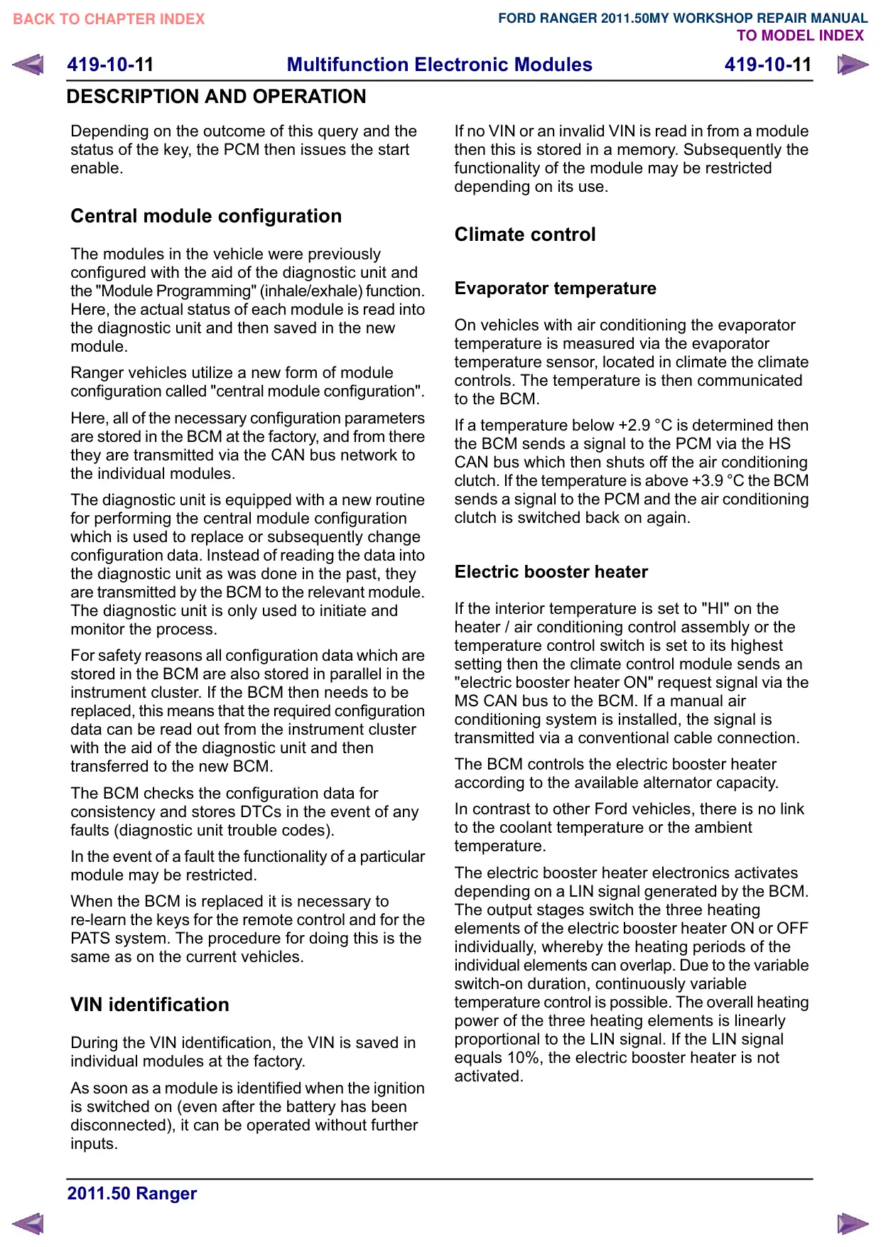
2.
E140119
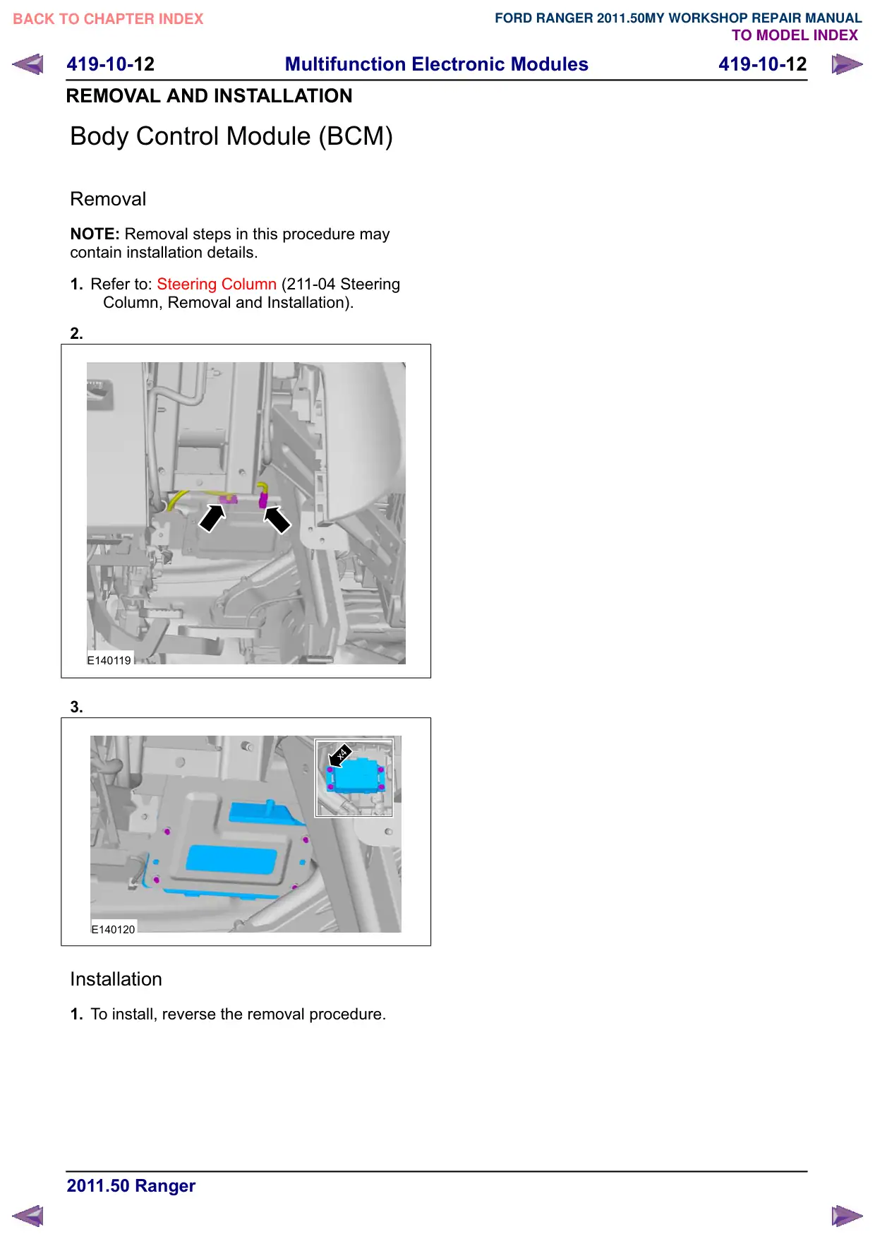
3.
x4
E140120
Installation
1. To install, reverse the removal procedure.