Funções controladas pelo módulo
Module Controlled Functions
Texto da página
Link desta página: https://ranger.mbrace.com.br/oficina/1352
Imagem: https://ranger.mbrace.com.br/img/oficina/1352.webp
419-10-3
Multifunction Electronic Modules
419-10-3
DESCRIPTION AND OPERATION
Item
Description
1
HS CAN bus
2
MS CAN bus
3
Gateway (BCM)
4
%&0
5
Front window wiper motors
6
Headlamp
7
Window washer pump
8
Stoplamp switch
Ignition lock
10
Fuel level sensor
11
Instrument cluster
12
PATS transceiver (vehicles without
keyless vehicle module only)
13
Multifunction switch
14
Speed control switch
15
Hazard flasher switch
16
Brake fluid level switch
17
Light/rain sensor
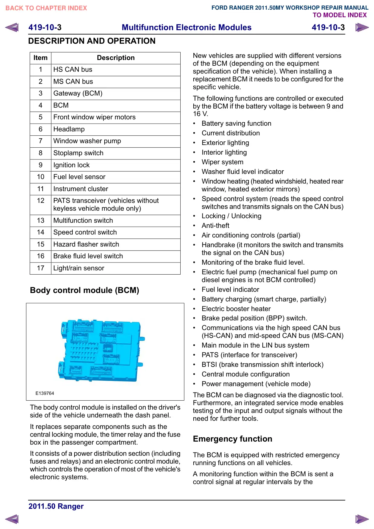
Body control module (BCM)
E139764
The body control module is installed on the driver's
side of the vehicle underneath the dash panel.
It replaces separate components such as the
central locking module, the timer relay and the fuse
box in the passenger compartment.
It consists of a power distribution section (including
fuses and relays) and an electronic control module,
which controls the operation of most of the vehicle's
electronic systems.
New vehicles are supplied with different versions
of the BCM (depending on the equipment
specification of the vehicle). When installing a
replacement BCM it needs to be configured for the
specific vehicle.
The following functions are controlled or executed
by the BCM if the battery voltage is between 9 and
16 V.
Battery saving function
Current distribution
Exterior lighting
Interior lighting
Wiper system
Washer fluid level indicator
Window heating (heated windshield, heated rear
window, heated exterior mirrors)
Speed control system (reads the speed control
switches and transmits signals on the CAN bus)
Locking / Unlocking
Anti-theft
Air conditioning controls (partial)
Handbrake (it monitors the switch and transmits
the signal on the CAN bus)
Monitoring of the brake fluid level.
Electric fuel pump (mechanical fuel pump on
diesel engines is not BCM controlled)
Fuel level indicator
Battery charging (smart charge, partially)
Electric booster heater
Brake pedal position (BPP) switch.
Communications via the high speed CAN bus
(HS-CAN) and mid-speed CAN bus (MS-CAN)
Main module in the LIN bus system
PATS (interface for transceiver)
BTSI (brake transmission shift interlock)
Central module configuration
Power management (vehicle mode)
The BCM can be diagnosed via the diagnostic tool.
Furthermore, an integrated service mode enables
testing of the input and output signals without the
need for further tools.
Emergency function
The BCM is equipped with restricted emergency
running functions on all vehicles.
A monitoring function within the BCM is sent a
control signal at regular intervals by the