Engine System - General Information
303-00-2
303-00-2
GENERAL PROCEDURES
Camshaft Bearing Journal Diameter
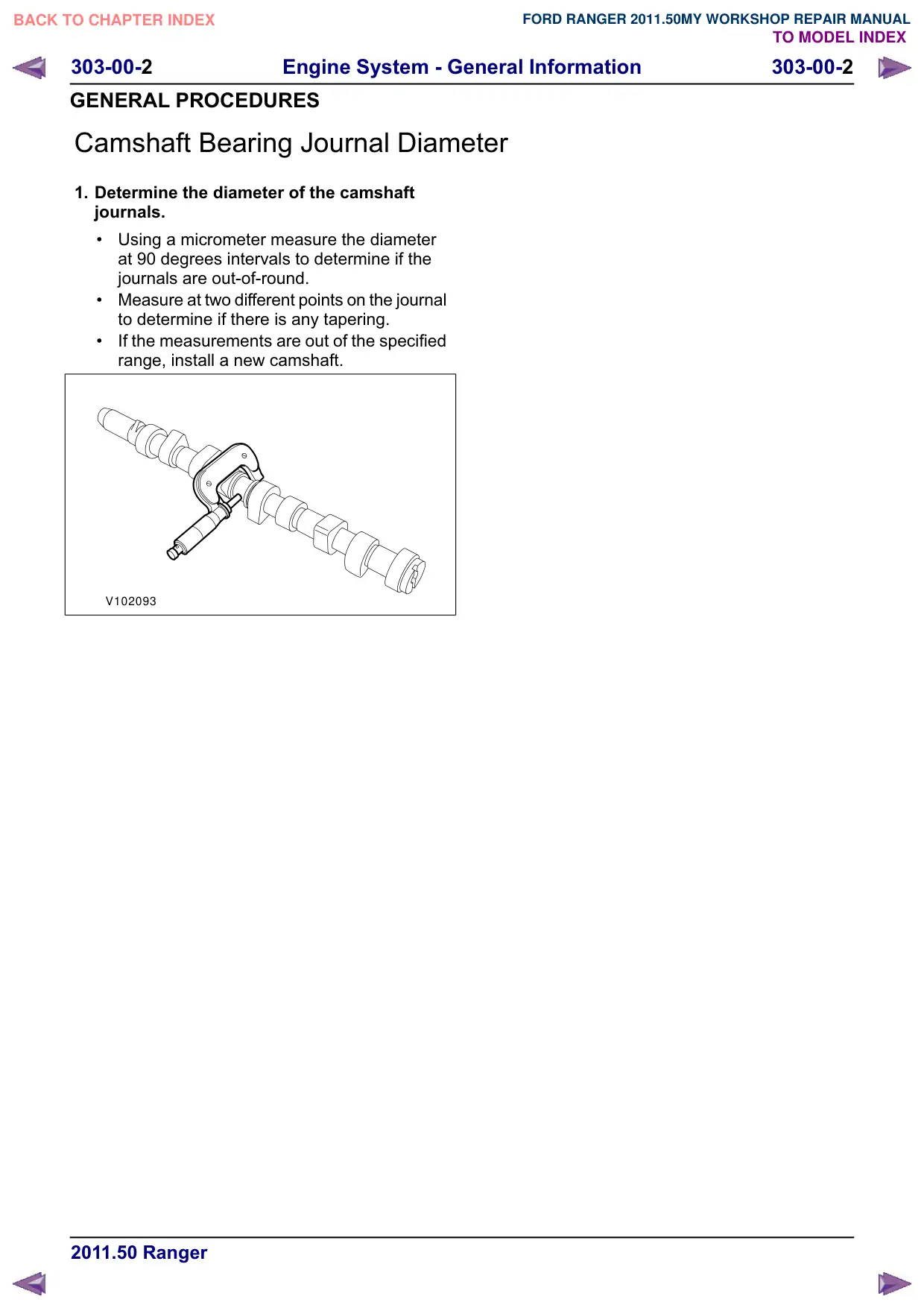
1. Determine the diameter of the camshaft
journals.
Using a micrometer measure the diameter
at 90 degrees intervals to determine if the
journals are out-of-round.
Measure at two different points on the journal
to determine if there is any tapering.
If the measurements are out of the specified
range, install a new camshaft.
V102093
Engine System - General Information
303-00-3
303-00-3
GENERAL PROCEDURES
Camshaft Bearing Journal Clearance
1. NOTE: Make sure that the following stages
are followed exactly. The tappets or followers
must be removed to carry out this
measurement.
NOTE: Make sure that the camshaft is to
specification.
NOTE: The bearing caps and journals should be
free from engine oil and dirt.
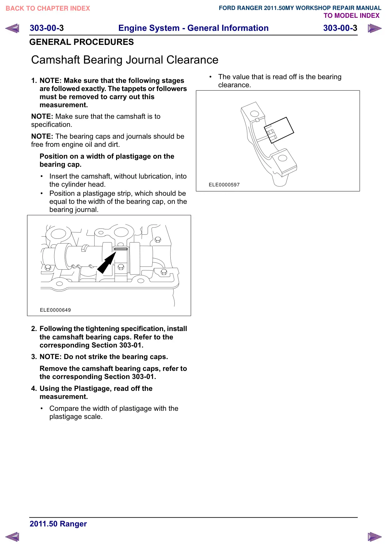
Position on a width of plastigage on the
bearing cap.
Insert the camshaft, without lubrication, into
the cylinder head.
Position a plastigage strip, which should be
equal to the width of the bearing cap, on the
bearing journal.
ELE0000649
2. Following the tightening specification, install
the camshaft bearing caps. Refer to the
corresponding Section 303-01.
3. NOTE: Do not strike the bearing caps.
Remove the camshaft bearing caps, refer to
the corresponding Section 303-01.
4. Using the Plastigage, read off the
measurement.
Compare the width of plastigage with the
plastigage scale.
The value that is read off is the bearing
clearance.
ELE0000597
Engine System - General Information
303-00-4
303-00-4
GENERAL PROCEDURES
Camshaft End Play
1. NOTE: Make sure that the camshaft is to
specification.
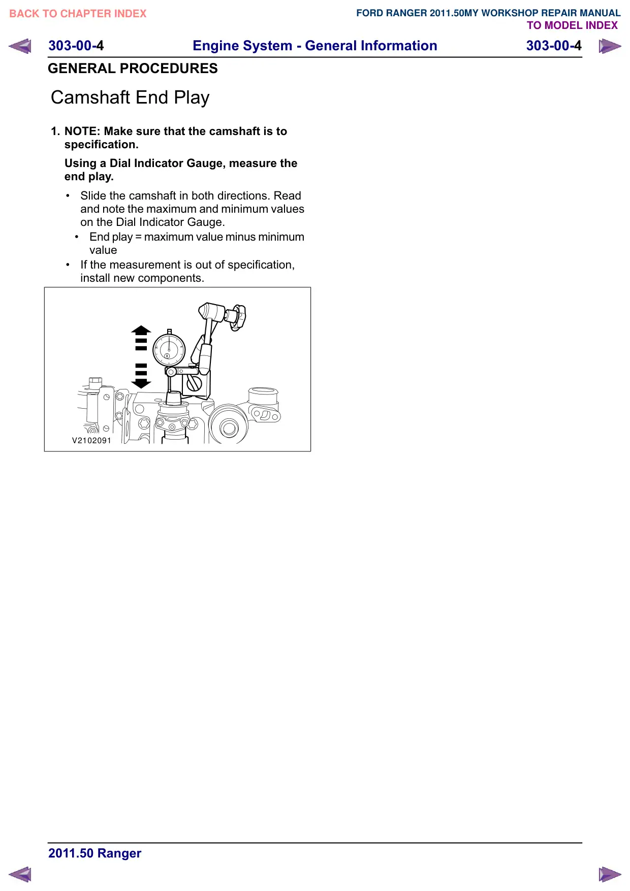
Using a Dial Indicator Gauge, measure the
end play.
Slide the camshaft in both directions. Read
and note the maximum and minimum values
on the Dial Indicator Gauge.
End play maximum value minus minimum
value
If the measurement is out of specification,
install new components.
V2102091
Engine System - General Information
303-00-5
303-00-5
GENERAL PROCEDURES
Camshaft Surface Inspection
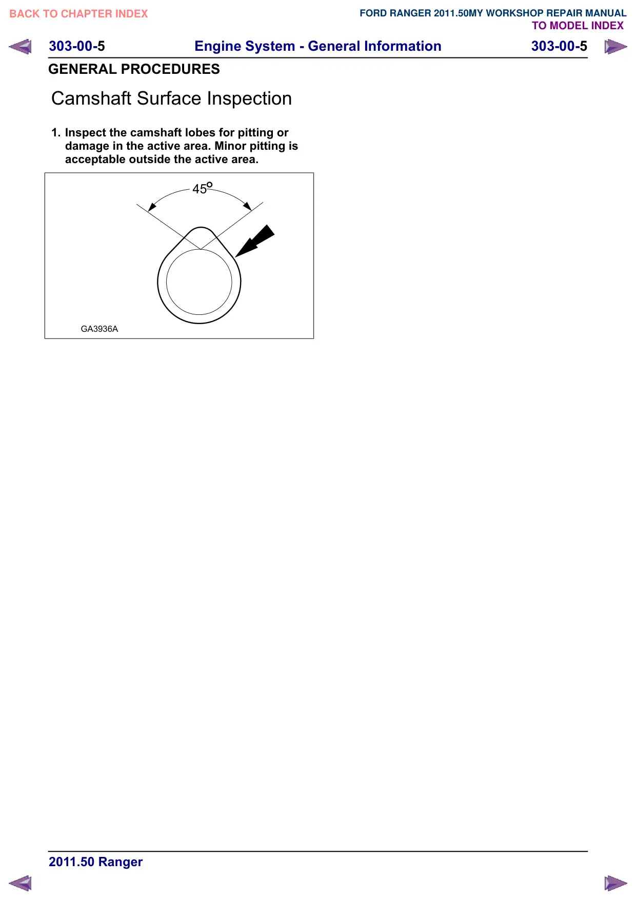
1. Inspect the camshaft lobes for pitting or
damage in the active area. Minor pitting is
acceptable outside the active area.
45
GA3936A
Engine System - General Information
303-00-6
303-00-6
GENERAL PROCEDURES
Camshaft Lobe Lift
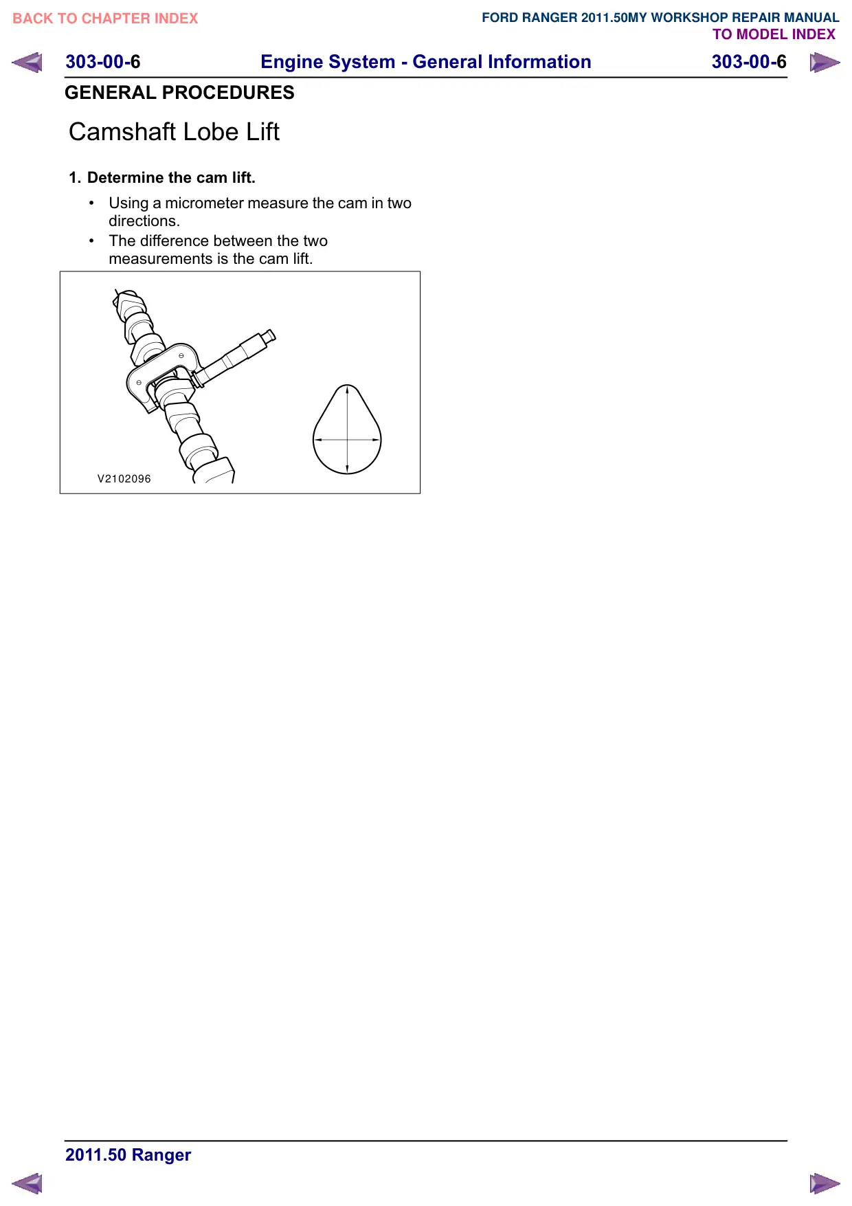
1. Determine the cam lift.
Using a micrometer measure the cam in two
directions.
The difference between the two
measurements is the cam lift.
V2102096
Engine System - General Information
303-00-7
303-00-7
GENERAL PROCEDURES
Crankshaft Main Bearing Journal Clearance
1. Information not available at time of going to
press.
Engine System - General Information
303-00-8
303-00-8
GENERAL PROCEDURES
Crankshaft Main Bearing Journal Diameter
General Equipment
Micrometer
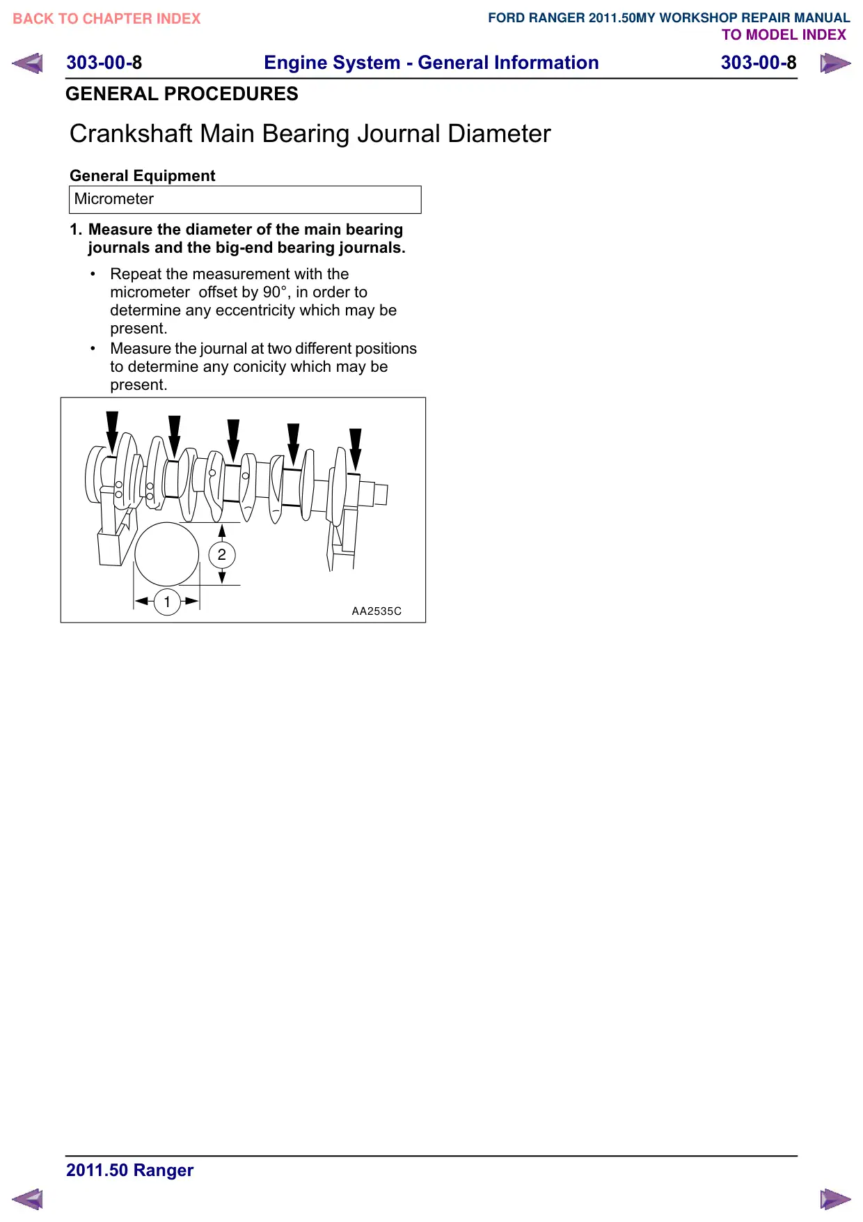
1. Measure the diameter of the main bearing
journals and the big-end bearing journals.
Repeat the measurement with the
micrometer offset by 90°, in order to
determine any eccentricity which may be
present.
Measure the journal at two different positions
to determine any conicity which may be
present.
2
1
AA2535C
Engine System - General Information
303-00-
303-00-
GENERAL PROCEDURES
Crankshaft End Play
General Equipment
Dial indicator
Dial indicator fixture
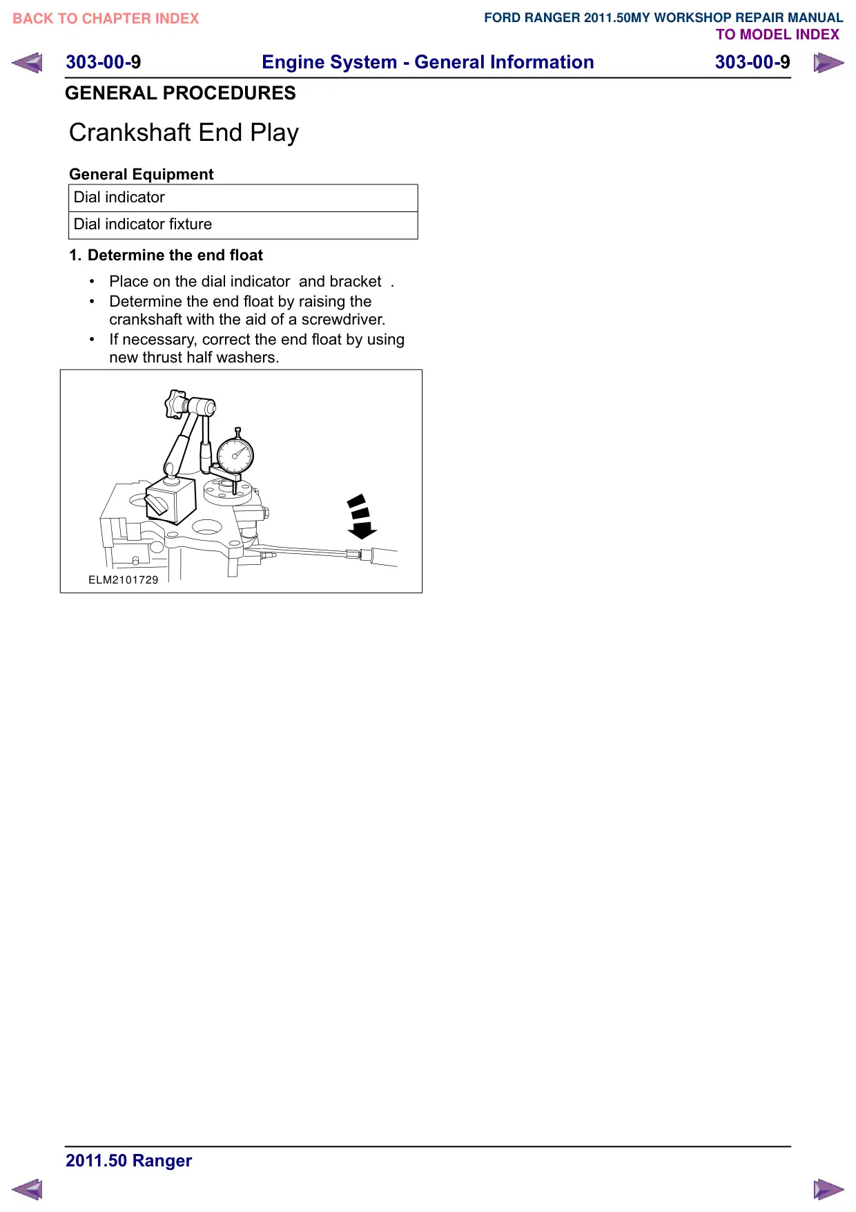
1. Determine the end float
Place on the dial indicator and bracket .
Determine the end float by raising the
crankshaft with the aid of a screwdriver.
If necessary, correct the end float by using
new thrust half washers.
ELM2101729
Engine System - General Information
303-00-10
303-00-10
GENERAL PROCEDURES
Cylinder Bore Taper
1. NOTE: The main bearing caps or lower
crankcase must be in place and tightened to
the specified torque; however, the bearing
shells should not be installed.
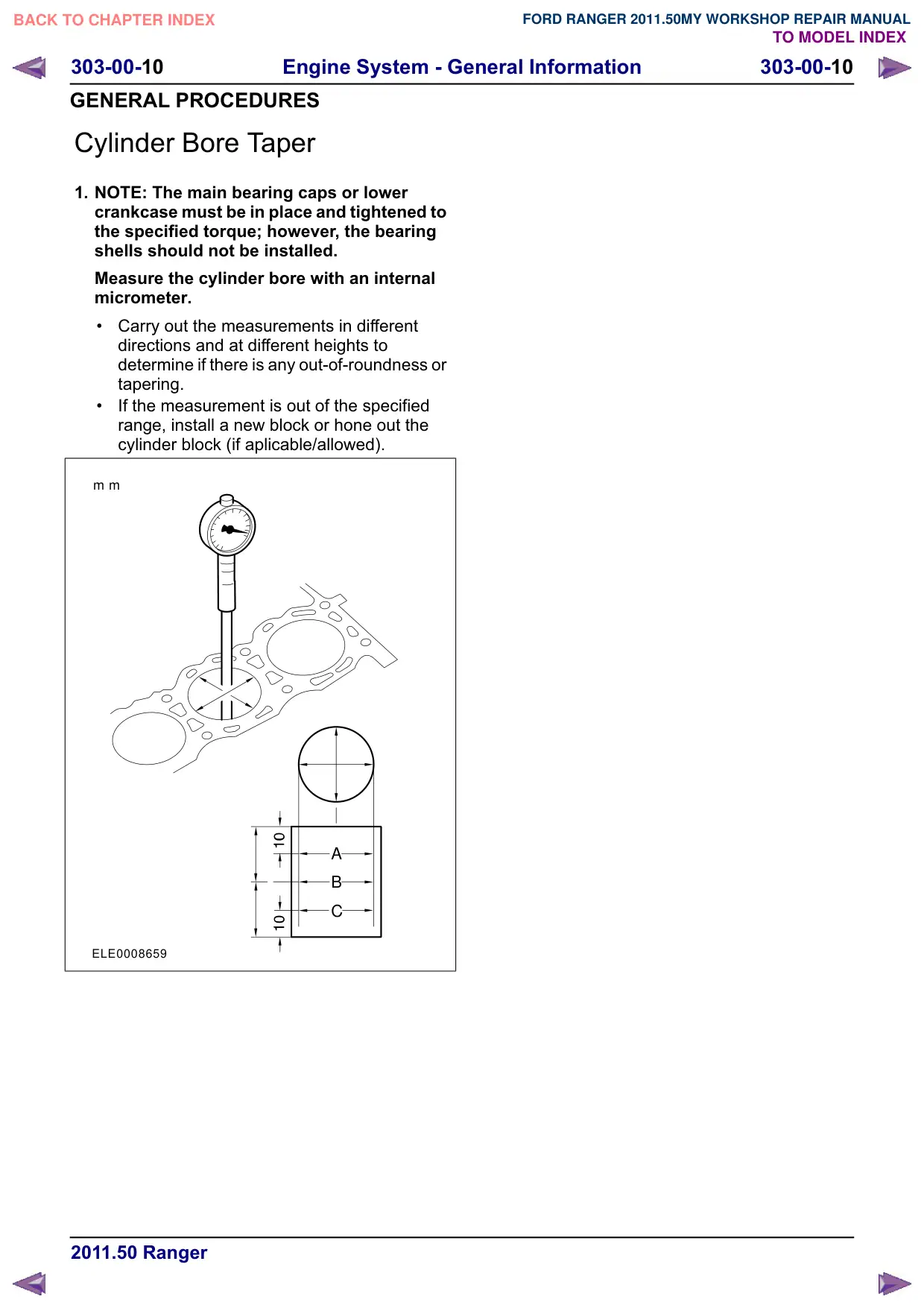
Measure the cylinder bore with an internal
micrometer.
Carry out the measurements in different
directions and at different heights to
determine if there is any out-of-roundness or
tapering.
If the measurement is out of the specified
range, install a new block or hone out the
cylinder block (if aplicable/allowed).
m m
A
B
C
ELE0008659
Engine System - General Information
303-00-11
303-00-11
GENERAL PROCEDURES
Piston Inspection
1.
CAUTION: Do not use any aggressive
cleaning fluid or a wire brush to clean the
piston.
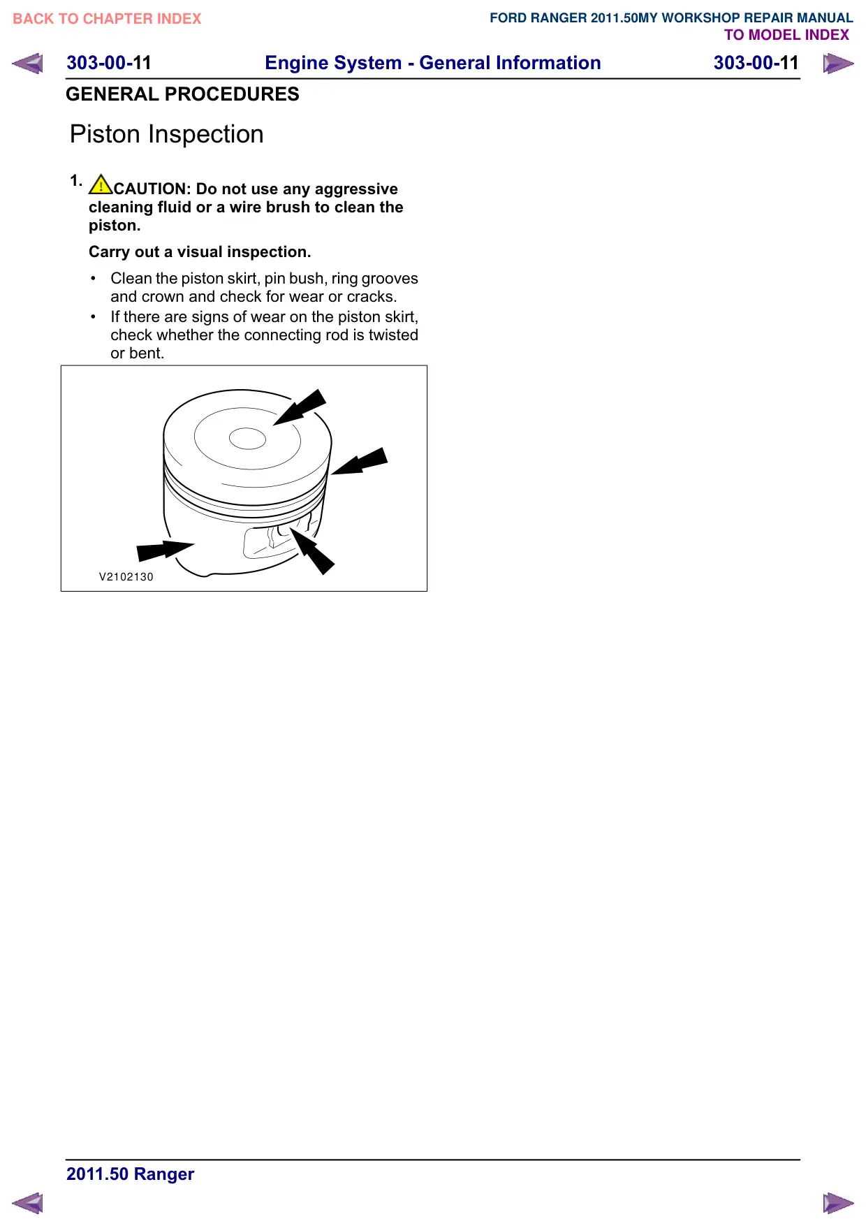
Carry out a visual inspection.
Clean the piston skirt, pin bush, ring grooves
and crown and check for wear or cracks.
If there are signs of wear on the piston skirt,
check whether the connecting rod is twisted
or bent.
V2102130
Engine System - General Information
303-00-12
303-00-12
GENERAL PROCEDURES
Piston Pin to Bore Diameter
1. NOTE: The piston and piston pin form a
matched pair. Do not mix up the
components.
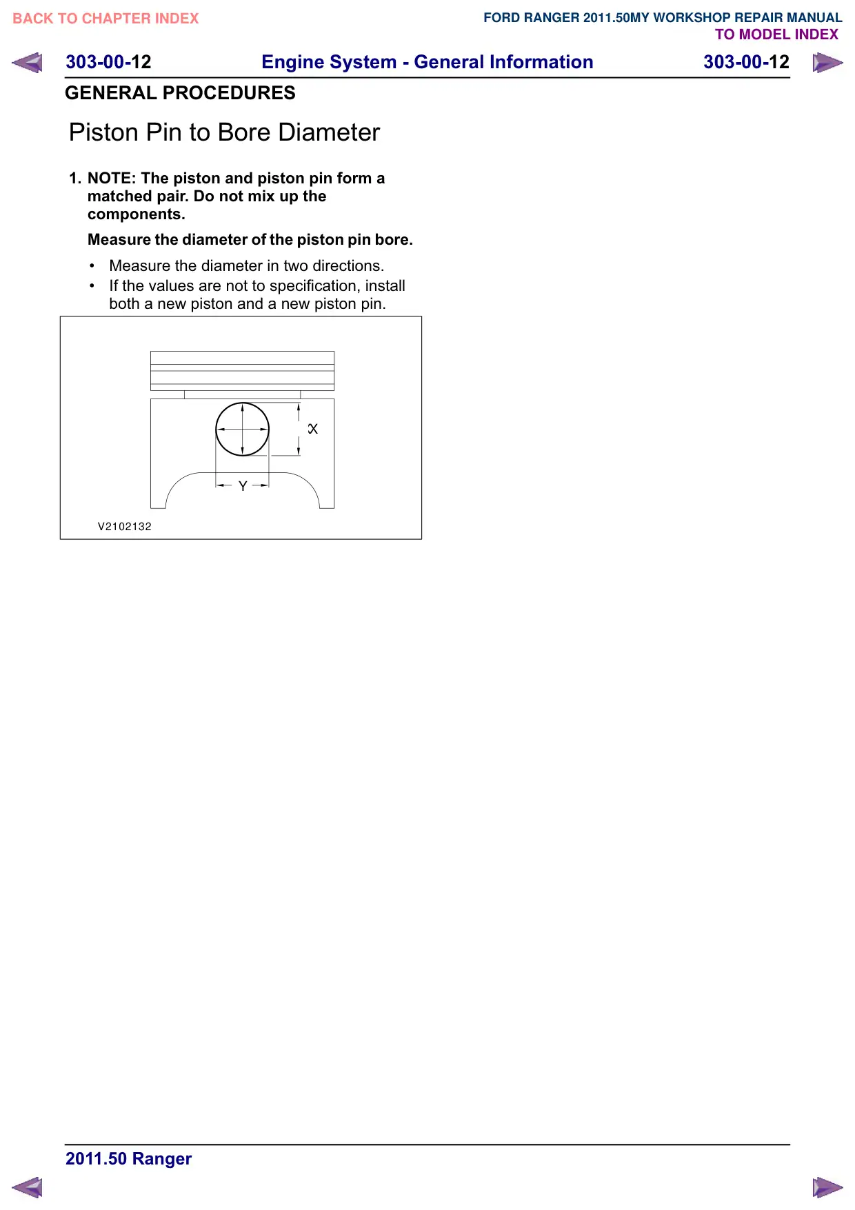
Measure the diameter of the piston pin bore.
Measure the diameter in two directions.
If the values are not to specification, install
both a new piston and a new piston pin.
xXX
Y
V2102132
Engine System - General Information
303-00-13
303-00-13
GENERAL PROCEDURES
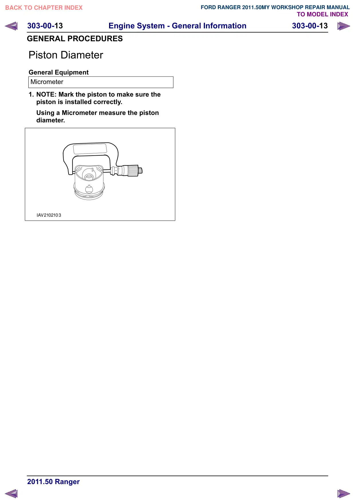
Piston Diameter
General Equipment
Micrometer
1. NOTE: Mark the piston to make sure the
piston is installed correctly.
Using a Micrometer measure the piston
diameter.
I A V 2 1 0 2 1 0 3
Engine System - General Information
303-00-14
303-00-14
GENERAL PROCEDURES
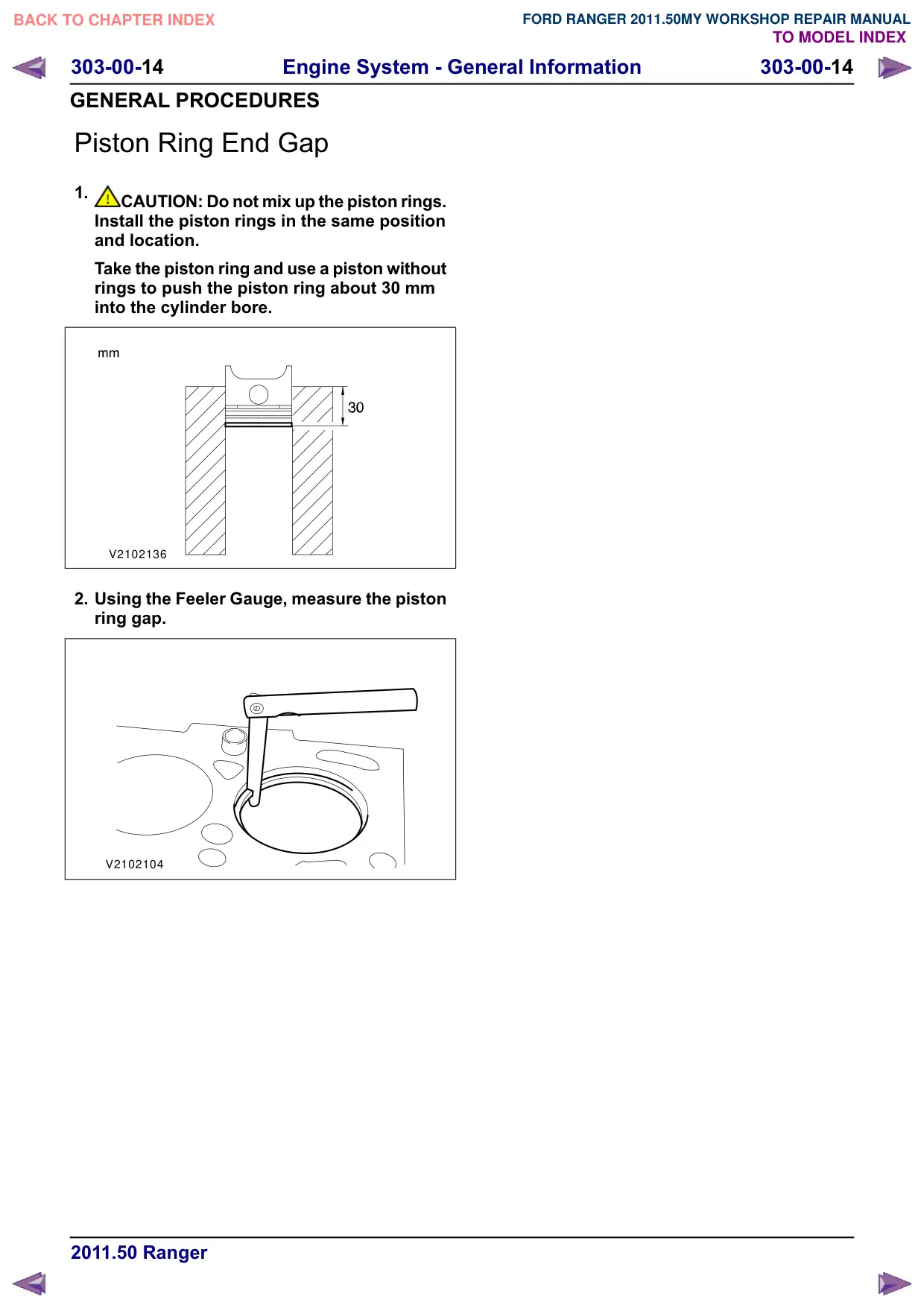
Piston Ring End Gap
1.
CAUTION: Do not mix up the piston rings.
Install the piston rings in the same position
and location.
Take the piston ring and use a piston without
rings to push the piston ring about 30 mm
into the cylinder bore.
V2102136
2. Using the Feeler Gauge, measure the piston
ring gap.
V2102104
Engine System - General Information
303-00-15
303-00-15
GENERAL PROCEDURES
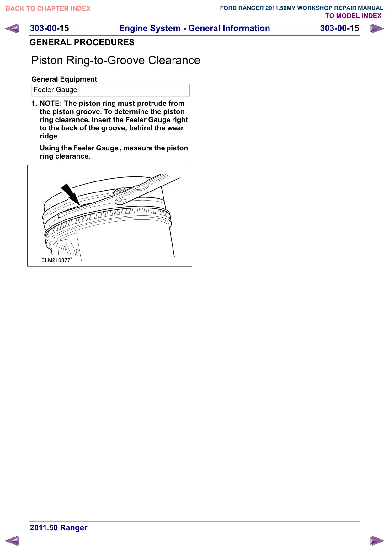
Piston Ring-to-Groove Clearance
General Equipment
Feeler Gauge
1. NOTE: The piston ring must protrude from
the piston groove. To determine the piston
ring clearance, insert the Feeler Gauge right
to the back of the groove, behind the wear
ridge.
Using the Feeler Gauge , measure the piston
ring clearance.
ELM2103771
Engine System - General Information
303-00-16
303-00-16
GENERAL PROCEDURES
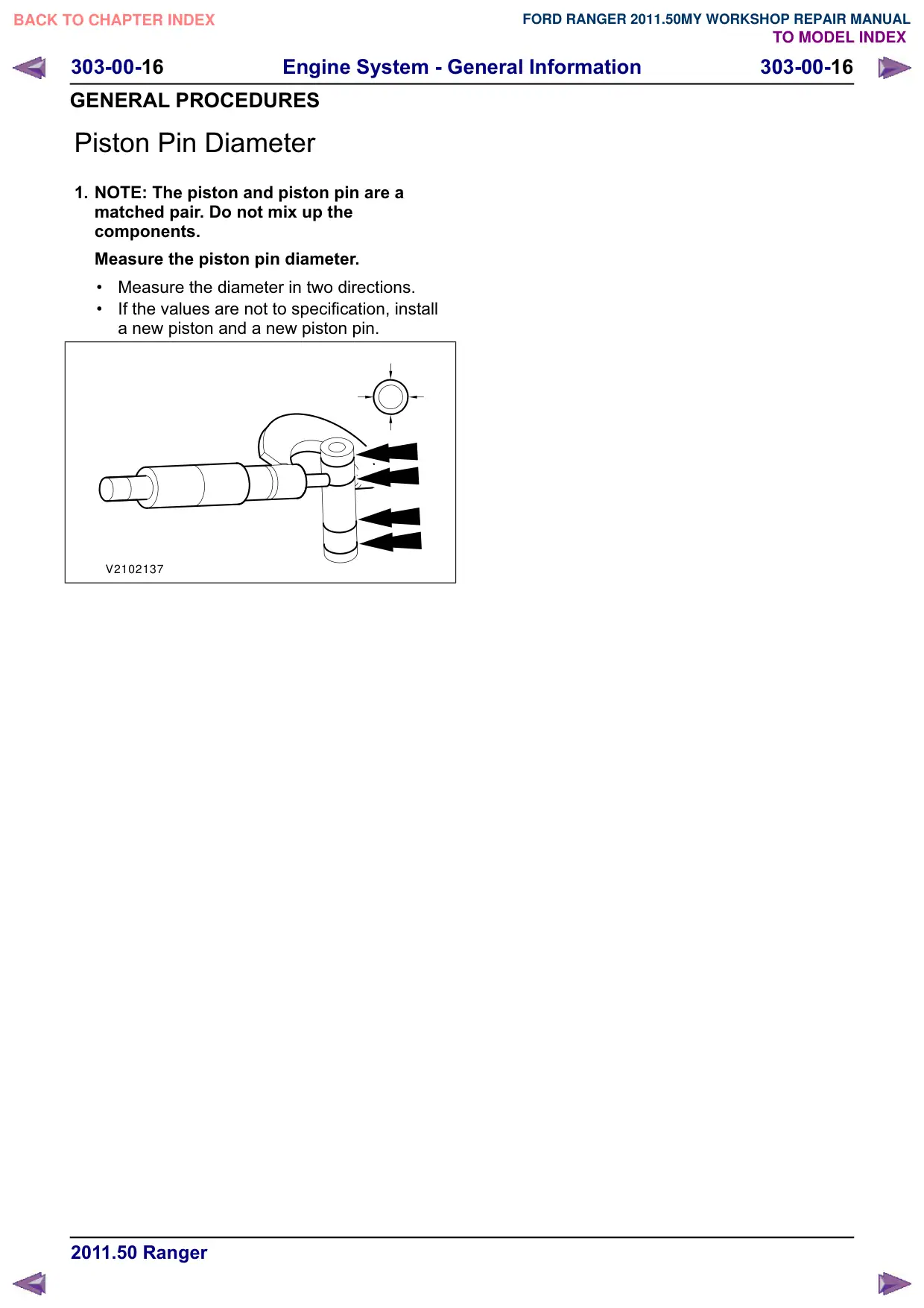
Piston Pin Diameter
1. NOTE: The piston and piston pin are a
matched pair. Do not mix up the
components.
Measure the piston pin diameter.
Measure the diameter in two directions.
If the values are not to specification, install
a new piston and a new piston pin.
V2102137
Engine System - General Information
303-00-17
303-00-17
GENERAL PROCEDURES
Connecting Rod Large End Bore
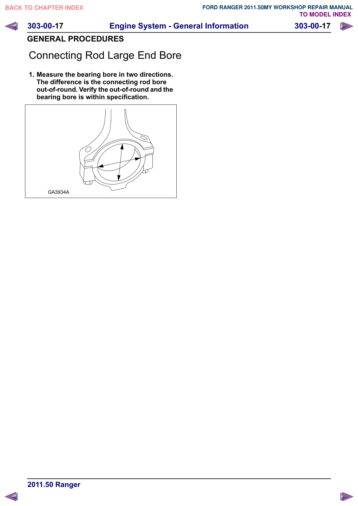
1. Measure the bearing bore in two directions.
The difference is the connecting rod bore
out-of-round. Verify the out-of-round and the
bearing bore is within specification.
GA3934A
Engine System - General Information
303-00-18
303-00-18
GENERAL PROCEDURES
Valve Stem Diameter
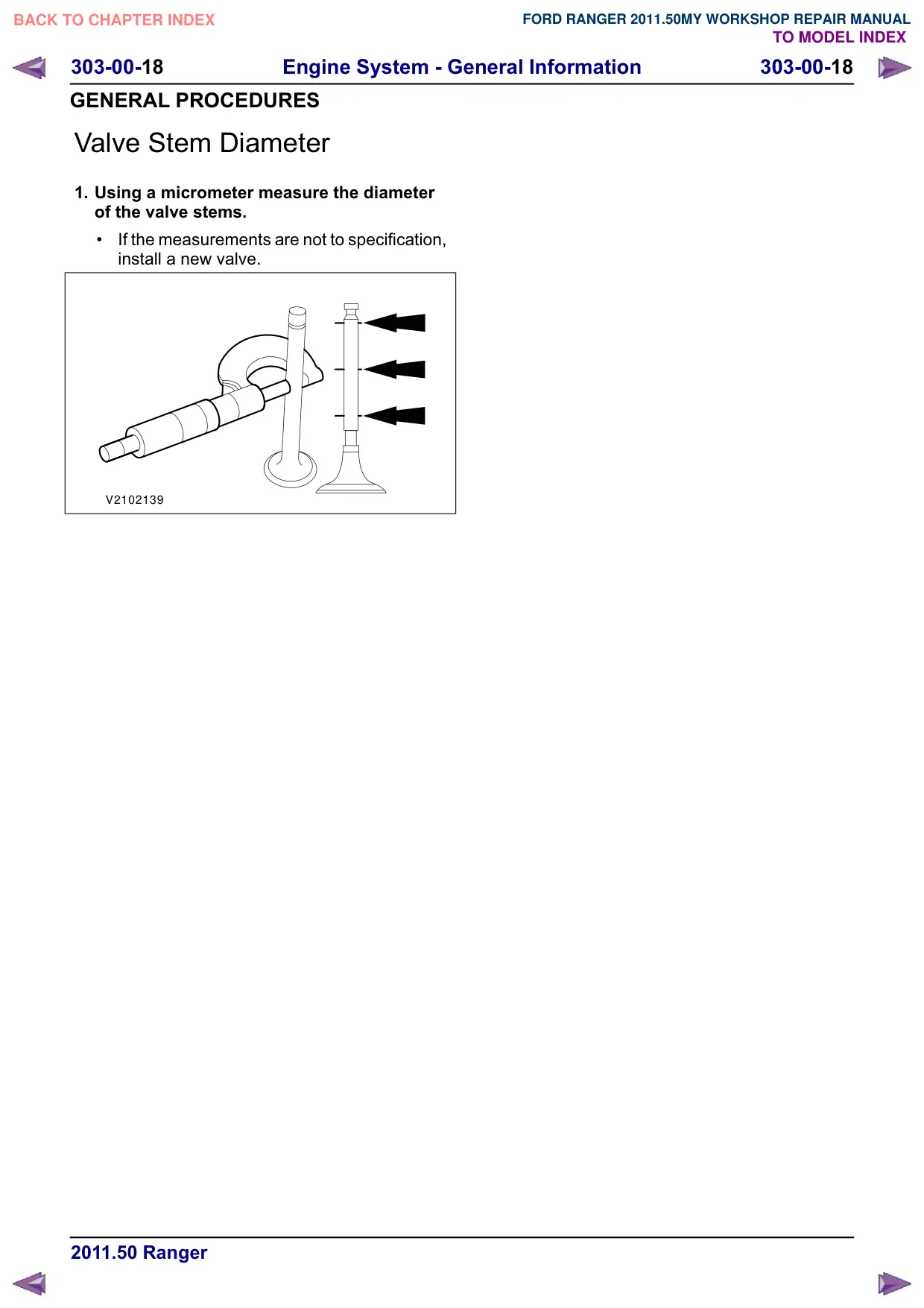
1. Using a micrometer measure the diameter
of the valve stems.
If the measurements are not to specification,
install a new valve.
V2102139
Engine System - General Information
303-00-19
303-00-19
GENERAL PROCEDURES
Valve Seat Inspection
General Equipment
Valve seat width scale
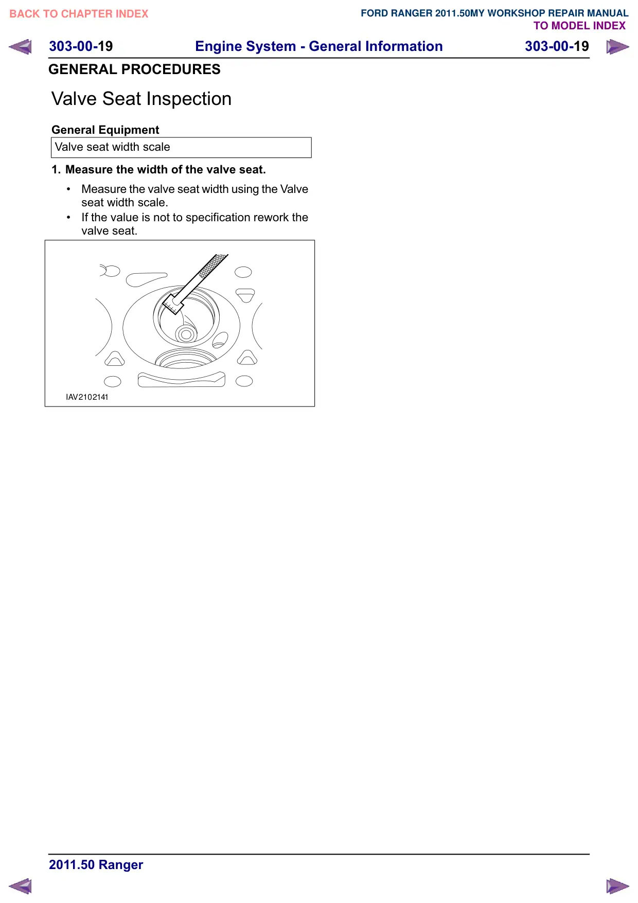
1. Measure the width of the valve seat.
Measure the valve seat width using the Valve
seat width scale.
If the value is not to specification rework the
valve seat.
I A V 2 1 0 2 1 4 1
Engine System - General Information
303-00-20
303-00-20
GENERAL PROCEDURES
Flywheel Inspection
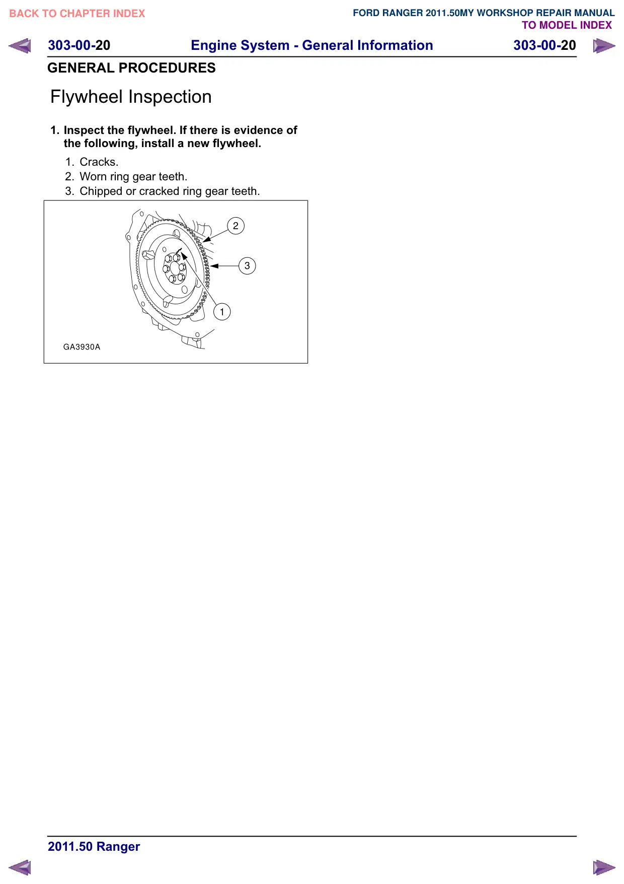
1. Inspect the flywheel. If there is evidence of
the following, install a new flywheel.
1. Cracks.
2. Worn ring gear teeth.
3. Chipped or cracked ring gear teeth.
2
3
1
GA3930A
Engine System - General Information
303-00-21
303-00-21
GENERAL PROCEDURES
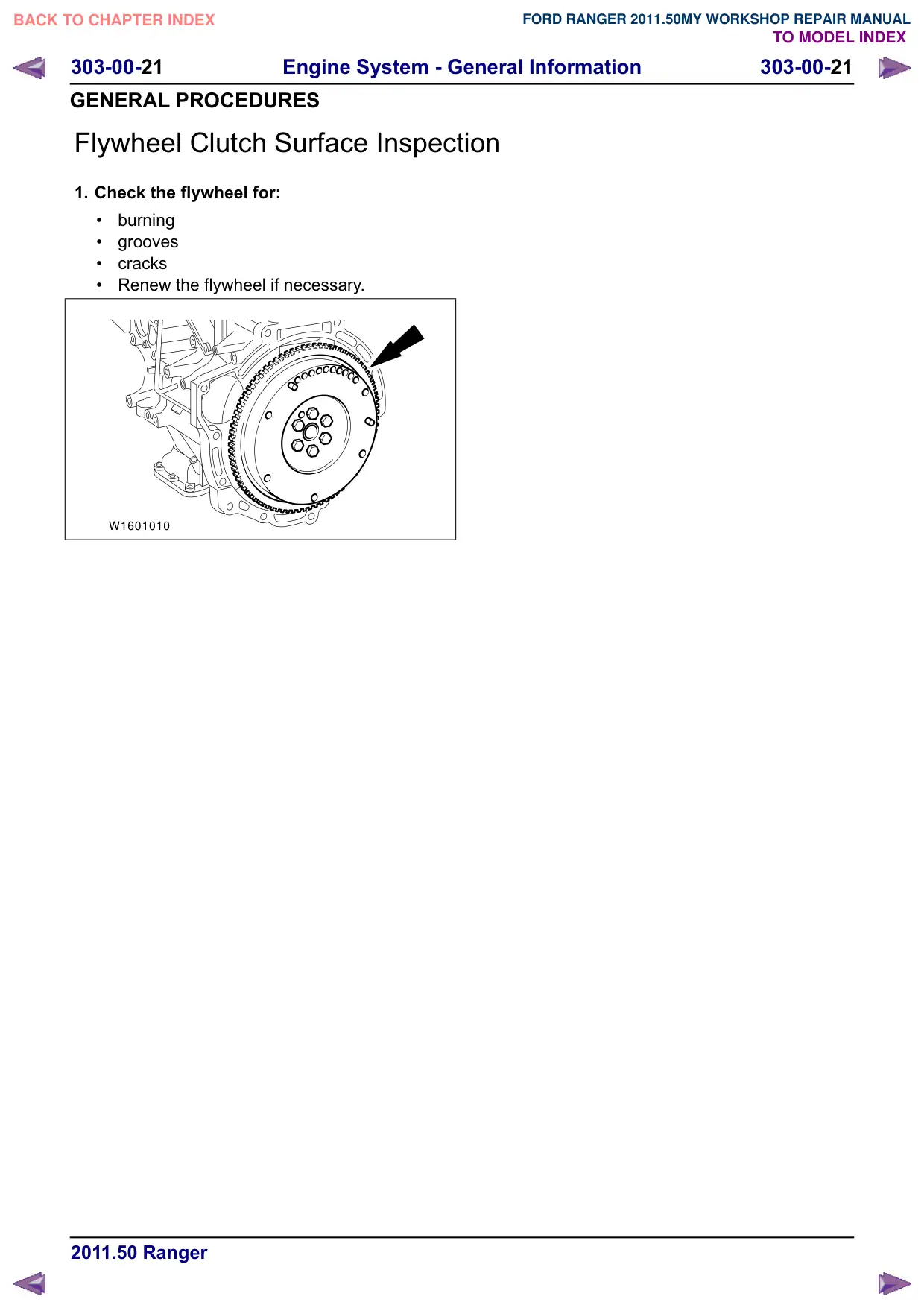
Flywheel Clutch Surface Inspection
1. Check the flywheel for:
burning
grooves
cracks
Renew the flywheel if necessary.
W1601010
Engine System - General Information
303-00-22
303-00-22
GENERAL PROCEDURES
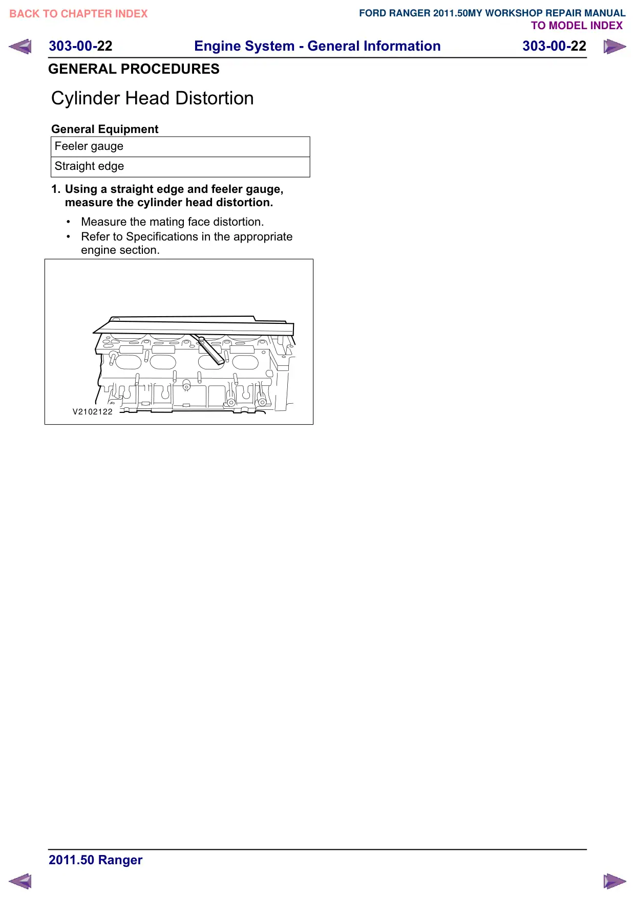
Cylinder Head Distortion
General Equipment
Feeler gauge
Straight edge
1. Using a straight edge and feeler gauge,
measure the cylinder head distortion.
Measure the mating face distortion.
Refer to Specifications in the appropriate
engine section.
V2102122
Engine System - General Information
303-00-23
303-00-23
GENERAL PROCEDURES
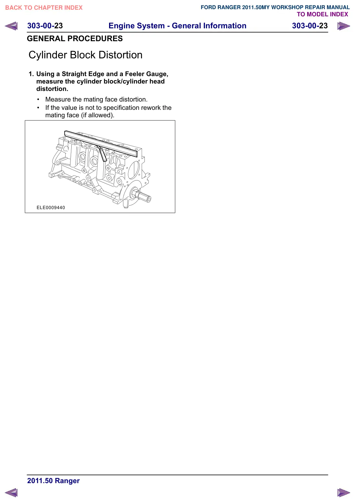
Cylinder Block Distortion
1. Using a Straight Edge and a Feeler Gauge,
measure the cylinder block/cylinder head
distortion.
Measure the mating face distortion.
If the value is not to specification rework the
mating face (if allowed).
ELE0009440
Engine System - General Information
303-00-24
303-00-24
GENERAL PROCEDURES
Exhaust Manifold Cleaning and Inspection
1. Inspect the cylinder head joining flanges of
the exhaust manifold for evidence of exhaust
gas leaks.
2. Inspect the exhaust manifold for cracks,
damaged gasket surfaces, or other damage
that would make it unfit for further use.