Anti-Lock Control
206-09A-2
206-09A-2
DESCRIPTION AND OPERATION
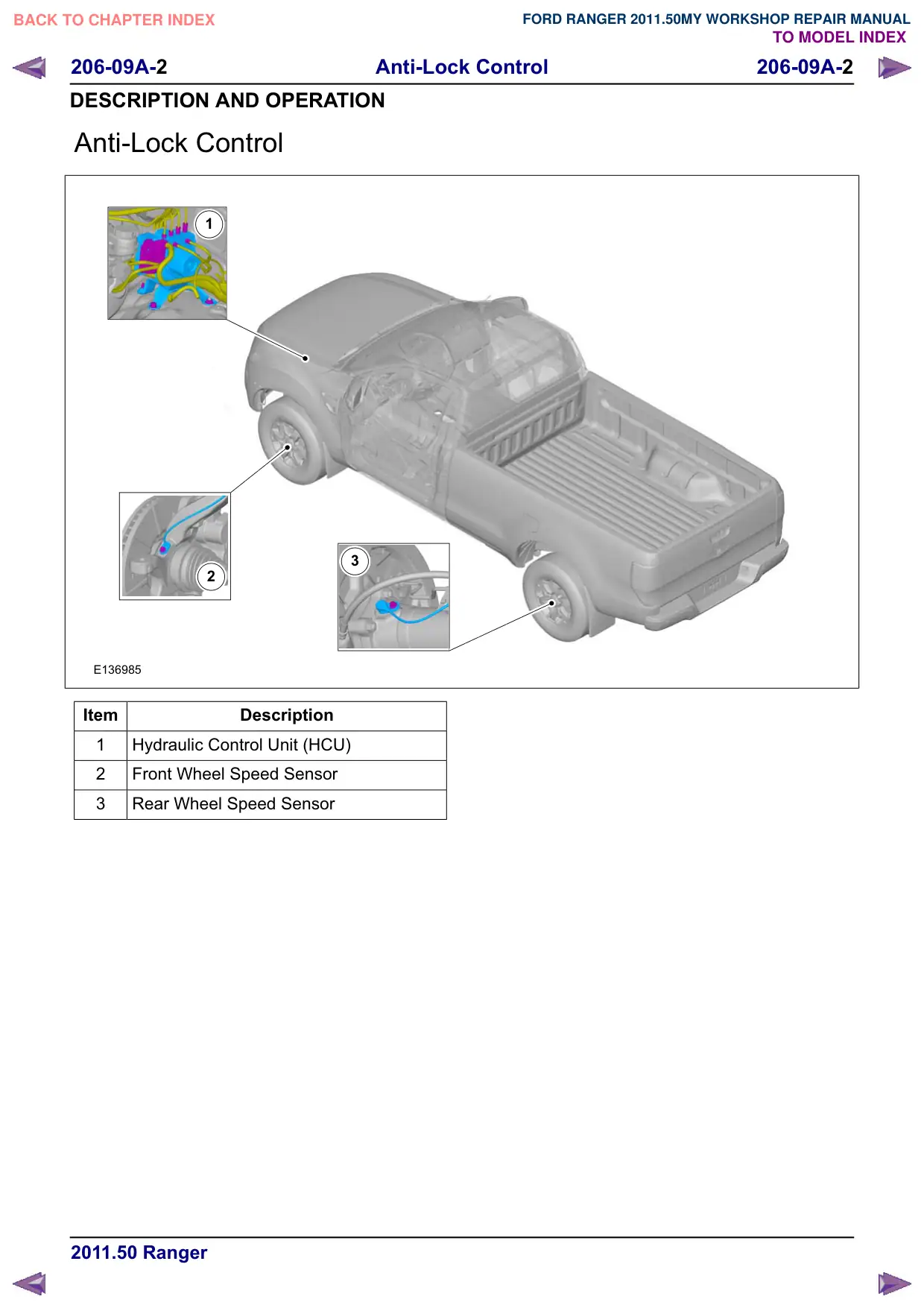
Anti-Lock Control
1
3
2
E136985
Item
Description
1
Hydraulic Control Unit (HCU)
2
Front Wheel Speed Sensor
3
Rear Wheel Speed Sensor
Anti-Lock Control
206-09A-3
206-09A-3
REMOVAL AND INSTALLATION
Hydraulic Control Unit (HCU) – LHD 4WD/LHD RWD
Removal
NOTE: Removal steps in this procedure may
contain installation details.
1. Refer to: Brake System Health and Safety
Precautions (100-00 General Information,
Description and Operation).
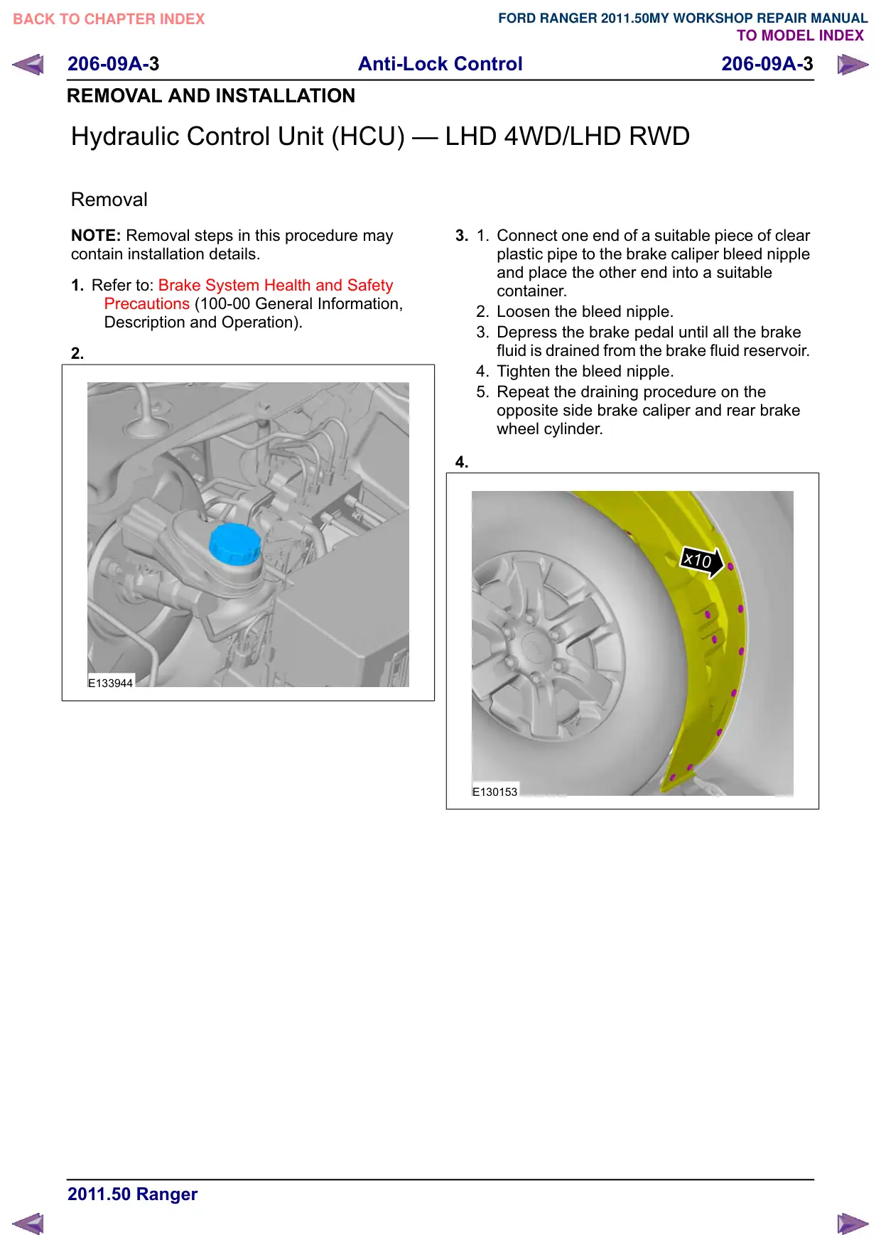
2.
E133944
3.
1.
Connect one end of a suitable piece of clear
plastic pipe to the brake caliper bleed nipple
and place the other end into a suitable
container.
2. Loosen the bleed nipple.
3. Depress the brake pedal until all the brake
fluid is drained from the brake fluid reservoir.
4. Tighten the bleed nipple.
5. Repeat the draining procedure on the
opposite side brake caliper and rear brake
wheel cylinder.
4.
x10
x10
E130153
Anti-Lock Control
206-09A-5
206-09A-5
REMOVAL AND INSTALLATION
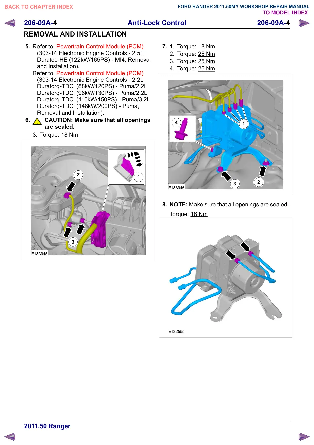
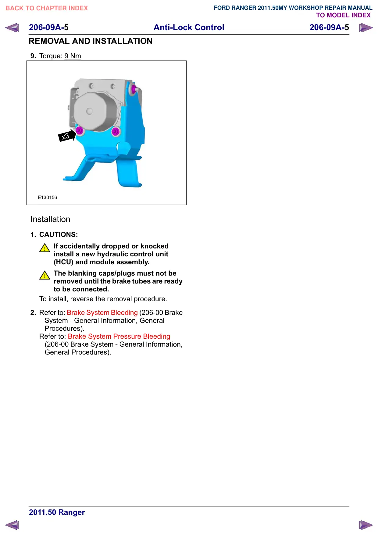
9. Torque: 9 Nm
x3
E130156
Installation
1. CAUTIONS:
If accidentally dropped or knocked
install a new hydraulic control unit
(HCU) and module assembly.
The blanking caps/plugs must not be
removed until the brake tubes are ready
to be connected.
To install, reverse the removal procedure.
2. Refer to: Brake System Bleeding (206-00 Brake
System - General Information, General
Procedures).
Refer to: Brake System Pressure Bleeding
(206-00 Brake System - General Information,
General Procedures).
Anti-Lock Control
206-09A-6
206-09A-6
REMOVAL AND INSTALLATION
Hydraulic Control Unit (HCU) – RHD 4WD/RHD RWD
Removal
NOTE: Removal steps in this procedure may
contain installation details.
1. Refer to: Brake System Health and Safety
Precautions (100-00 General Information,
Description and Operation).
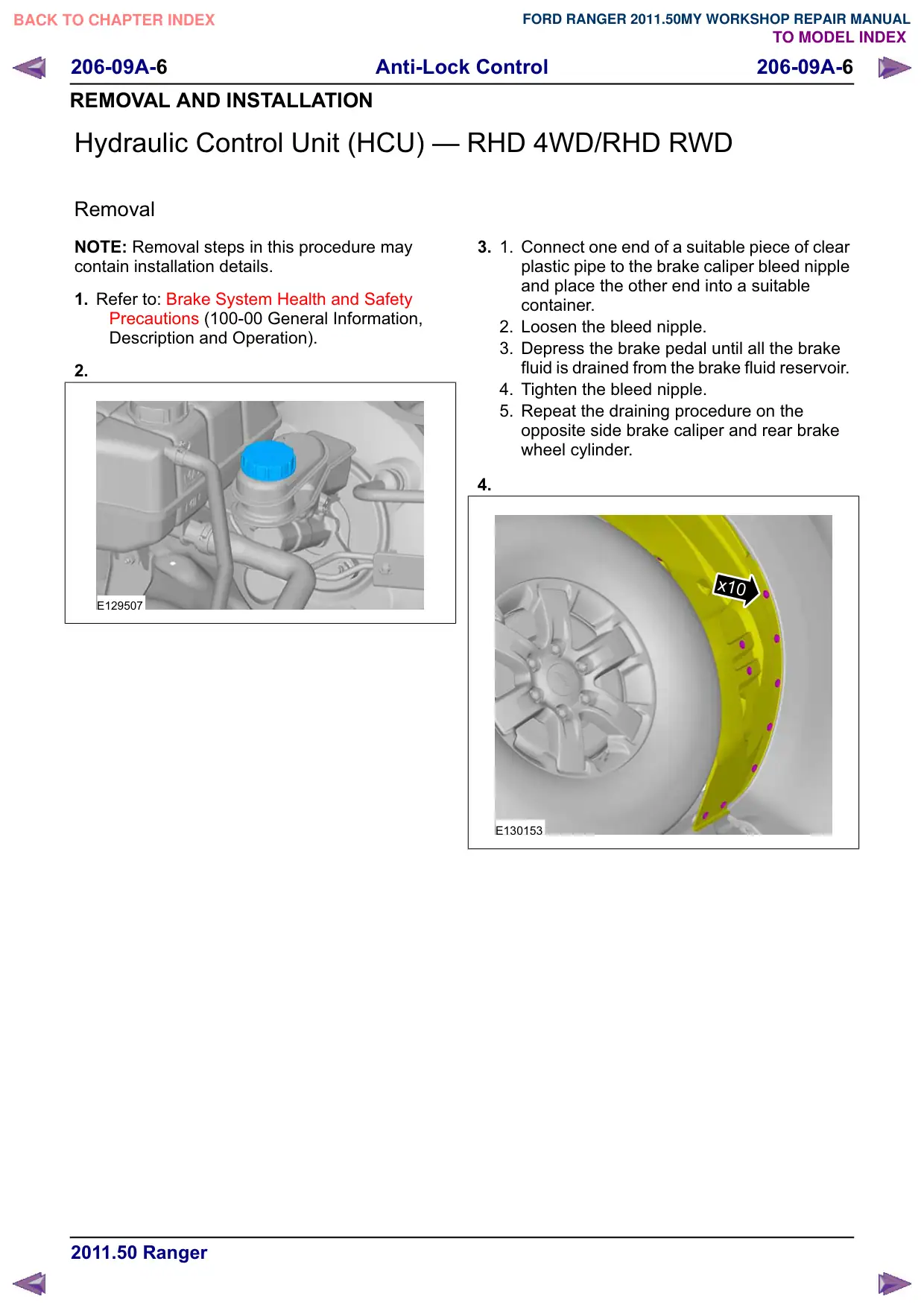
2.
E129507
3.
1.
Connect one end of a suitable piece of clear
plastic pipe to the brake caliper bleed nipple
and place the other end into a suitable
container.
2. Loosen the bleed nipple.
3. Depress the brake pedal until all the brake
fluid is drained from the brake fluid reservoir.
4. Tighten the bleed nipple.
5. Repeat the draining procedure on the
opposite side brake caliper and rear brake
wheel cylinder.
4.
x10
x10
E130153
Anti-Lock Control
206-09A-7
206-09A-7
REMOVAL AND INSTALLATION
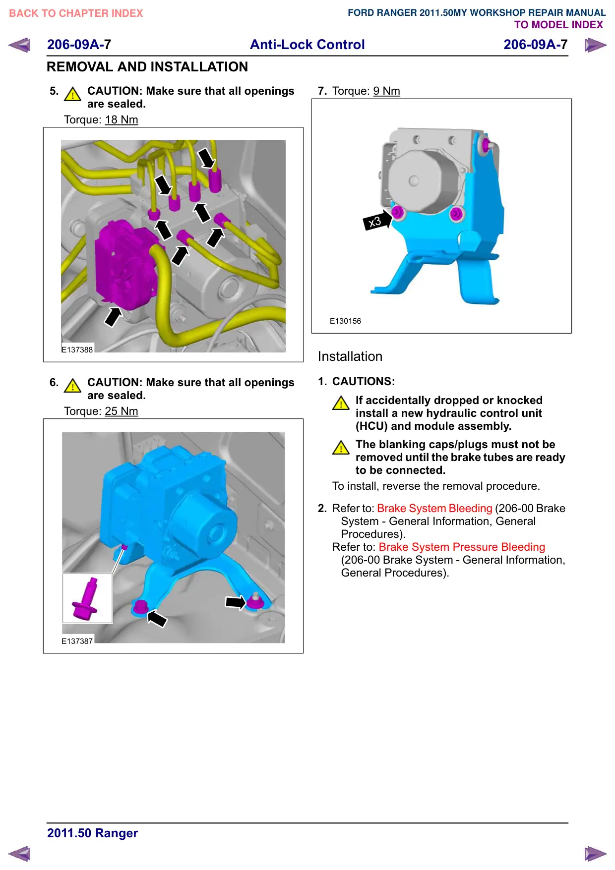
5.
CAUTION: Make sure that all openings
are sealed.
Torque: 18 Nm
E137388
6.
CAUTION: Make sure that all openings
are sealed.
Torque: 25 Nm
E137387
7. Torque: 9 Nm
x3
E130156
Installation
1. CAUTIONS:
If accidentally dropped or knocked
install a new hydraulic control unit
(HCU) and module assembly.
The blanking caps/plugs must not be
removed until the brake tubes are ready
to be connected.
To install, reverse the removal procedure.
2. Refer to: Brake System Bleeding (206-00 Brake
System - General Information, General
Procedures).
Refer to: Brake System Pressure Bleeding
(206-00 Brake System - General Information,
General Procedures).
Anti-Lock Control
206-09A-8
206-09A-8
REMOVAL AND INSTALLATION
Front Wheel Speed Sensor(12 784 0)
Removal
NOTE: Removal steps in this procedure may
contain installation details.
1. Refer to: Battery Disconnect and Connect
(414-01 Battery, Mounting and Cables,
General Procedures).
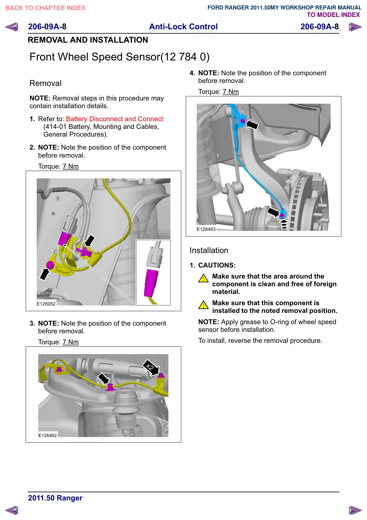
2. NOTE: Note the position of the component
before removal.
Torque: 7 Nm
E126052
3. NOTE: Note the position of the component
before removal.
Torque: 7 Nm
x2
E126462
4. NOTE: Note the position of the component
before removal.
Torque: 7 Nm
E126463
Installation
1. CAUTIONS:
Make sure that the area around the
component is clean and free of foreign
material.
Make sure that this component is
installed to the noted removal position.
NOTE: Apply grease to O-ring of wheel speed
sensor before installation.
To install, reverse the removal procedure.
Anti-Lock Control
206-09A-
206-09A-
REMOVAL AND INSTALLATION
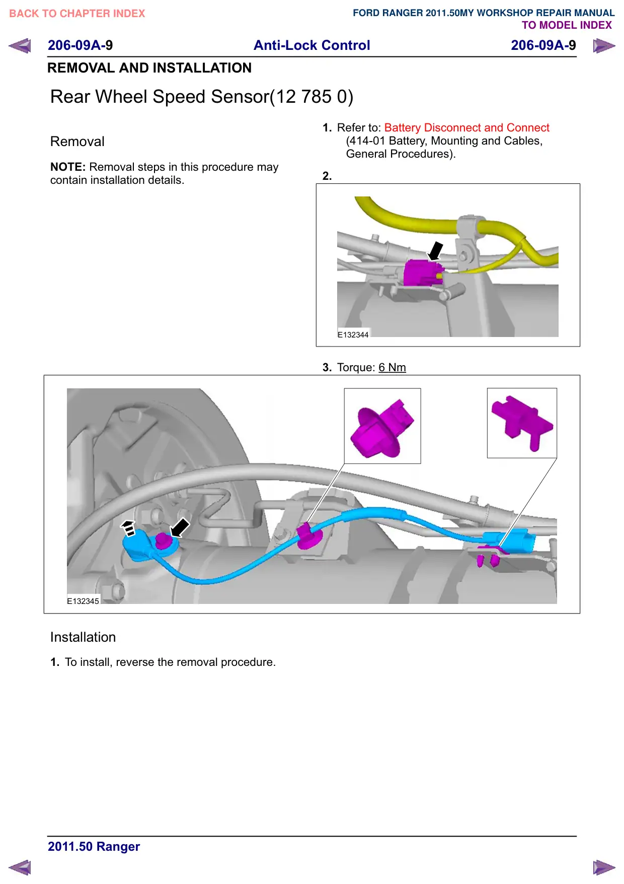
Rear Wheel Speed Sensor(12 785 0)
Removal
NOTE: Removal steps in this procedure may
contain installation details.
E132345
Installation
1. To install, reverse the removal procedure.
1. Refer to: Battery Disconnect and Connect
(414-01 Battery, Mounting and Cables,
General Procedures).
2.
E132344
3. Torque: 6 Nm