Front Drive Halfshafts
205-04-2
205-04-2
REMOVAL AND INSTALLATION
Front Halfshaft LH(14 320 0)
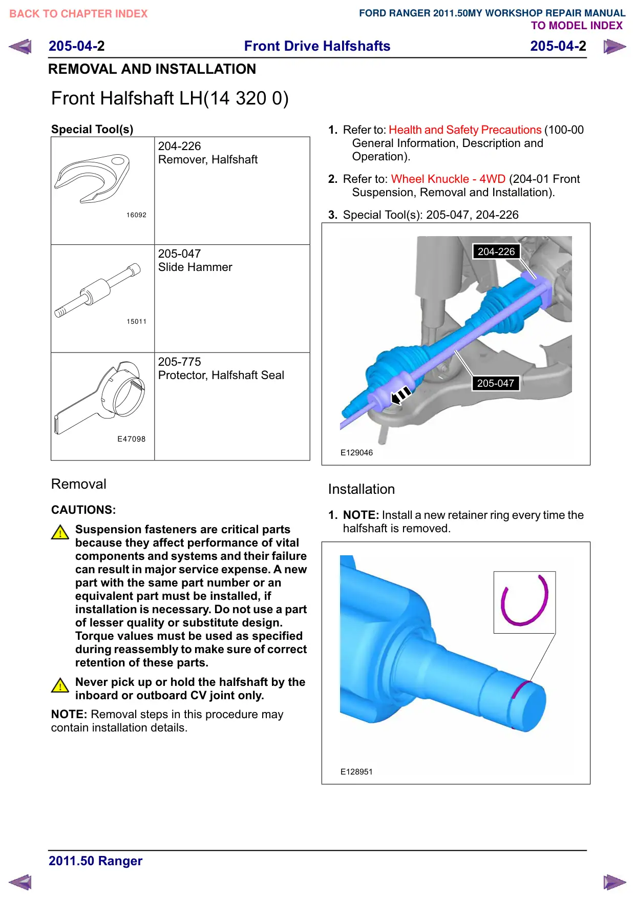
Special Tool(s)
204-226
Remover, Halfshaft
16092
205-047
Slide Hammer
15011
205-775
Protector, Halfshaft Seal
E47098
Removal
CAUTIONS:
Suspension fasteners are critical parts
because they affect performance of vital
components and systems and their failure
can result in major service expense. A new
part with the same part number or an
equivalent part must be installed, if
installation is necessary. Do not use a part
of lesser quality or substitute design.
Torque values must be used as specified
during reassembly to make sure of correct
retention of these parts.
Never pick up or hold the halfshaft by the
inboard or outboard CV joint only.
NOTE: Removal steps in this procedure may
contain installation details.
1. Refer to: Health and Safety Precautions (100-00
General Information, Description and
Operation).
2. Refer to: Wheel Knuckle - 4WD (204-01 Front
Suspension, Removal and Installation).
3. Special Tool(s): 205-047, 204-226
204-226
205-047
E129046
Installation
1. NOTE: Install a new retainer ring every time the
halfshaft is removed.
E128951
Front Drive Halfshafts
205-04-3
205-04-3
REMOVAL AND INSTALLATION
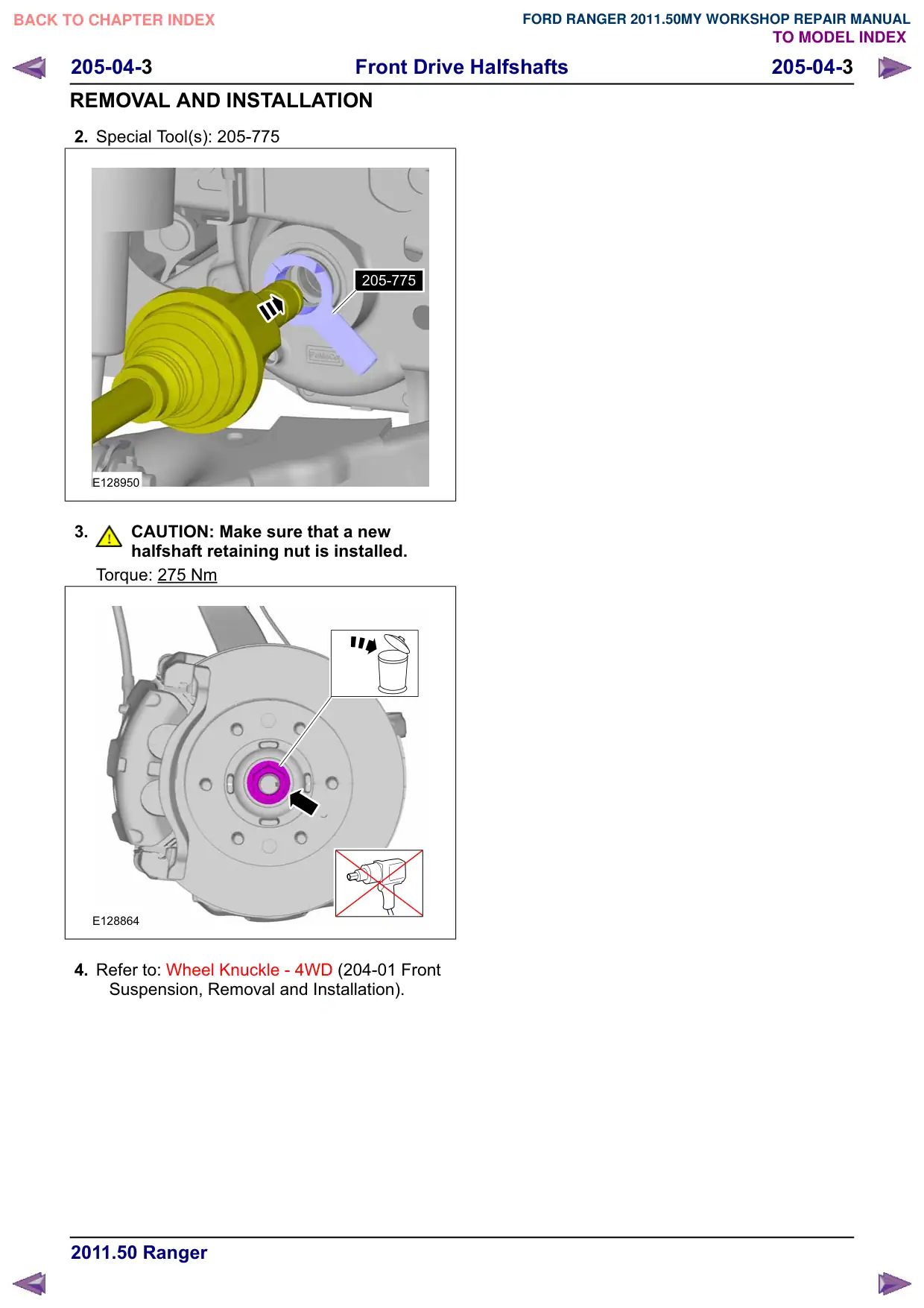
2. Special Tool(s): 205-775
205-775
E128950
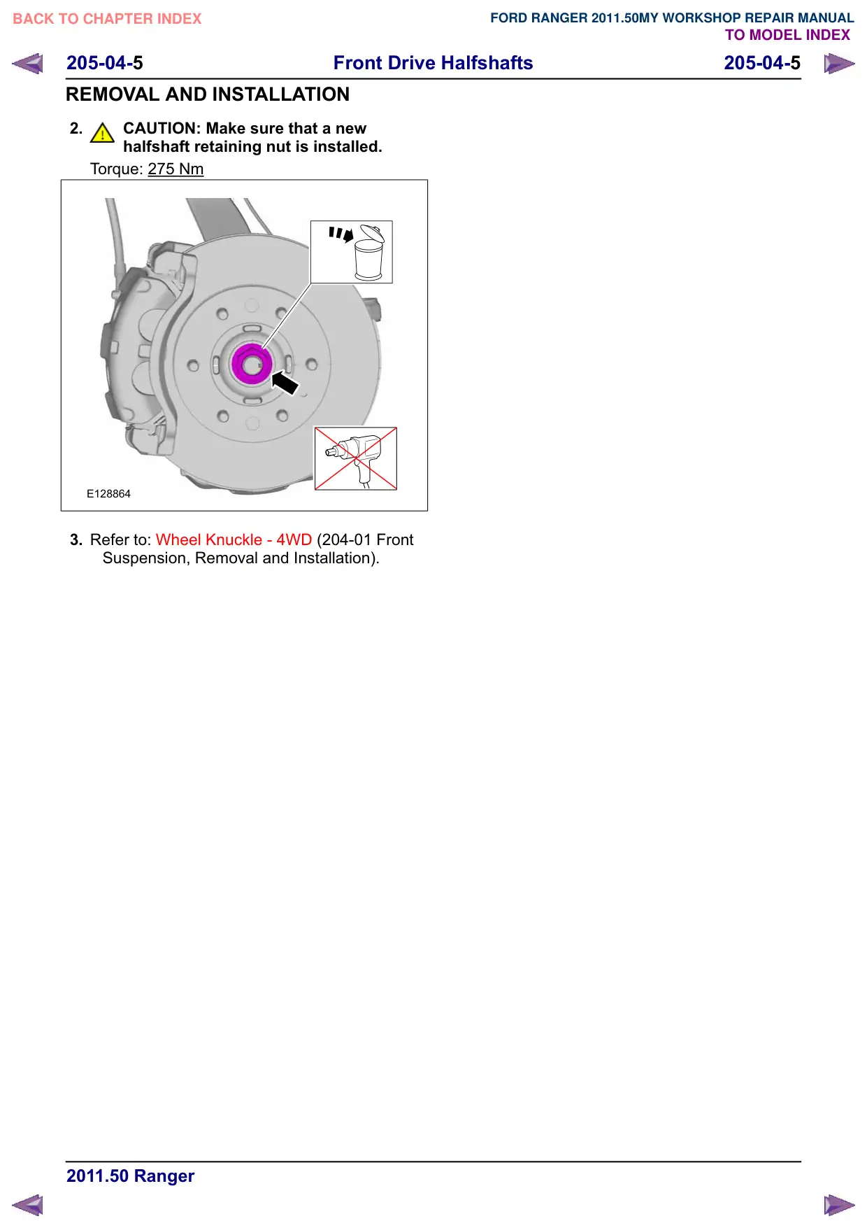
3.
CAUTION: Make sure that a new
halfshaft retaining nut is installed.
Torque: 275 Nm
E128864
4. Refer to: Wheel Knuckle - 4WD (204-01 Front
Suspension, Removal and Installation).
Front Drive Halfshafts
205-04-4
205-04-4
REMOVAL AND INSTALLATION
Front Halfshaft RH(14 321 0)
Removal
CAUTIONS:
Suspension fasteners are critical parts
because they affect performance of vital
components and systems and their failure
can result in major service expense. A new
part with the same part number or an
equivalent part must be installed, if
installation is necessary. Do not use a part
of lesser quality or substitute design.
Torque values must be used as specified
during reassembly to make sure of correct
retention of these parts.
Never pick up or hold the halfshaft by the
inboard or outboard CV joint only.
NOTE: Removal steps in this procedure may
contain installation details.
1. Refer to: Health and Safety Precautions (100-00
General Information, Description and
Operation).
2. Refer to: Wheel Knuckle - 4WD (204-01 Front
Suspension, Removal and Installation).
3.
CAUTION: Do not damage the axle shaft
oil seal, the machined sealing surface
on the inboard CV joint housing or the
axle shaft splines.
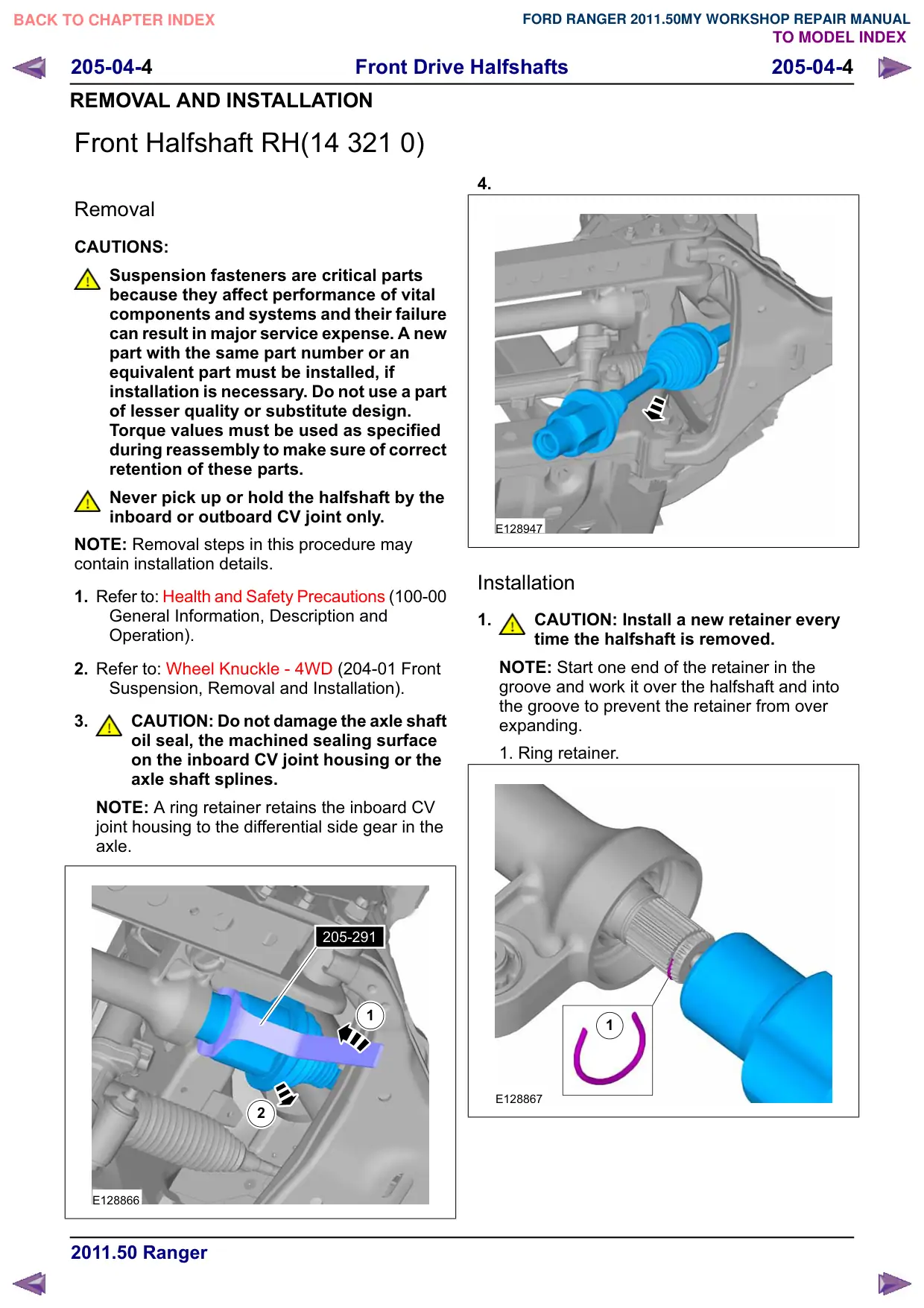
NOTE: A ring retainer retains the inboard CV
joint housing to the differential side gear in the
axle.
205-291
1
2
E128866
4.
E128947
Installation
1.
CAUTION: Install a new retainer every
time the halfshaft is removed.
NOTE: Start one end of the retainer in the
groove and work it over the halfshaft and into
the groove to prevent the retainer from over
expanding.
1. Ring retainer.
1
E128867
Front Drive Halfshafts
205-04-5
205-04-5
REMOVAL AND INSTALLATION
2.
CAUTION: Make sure that a new
halfshaft retaining nut is installed.
Torque: 275 Nm
E128864
3. Refer to: Wheel Knuckle - 4WD (204-01 Front
Suspension, Removal and Installation).
Front Drive Halfshafts
205-04-7
205-04-7
REMOVAL AND INSTALLATION
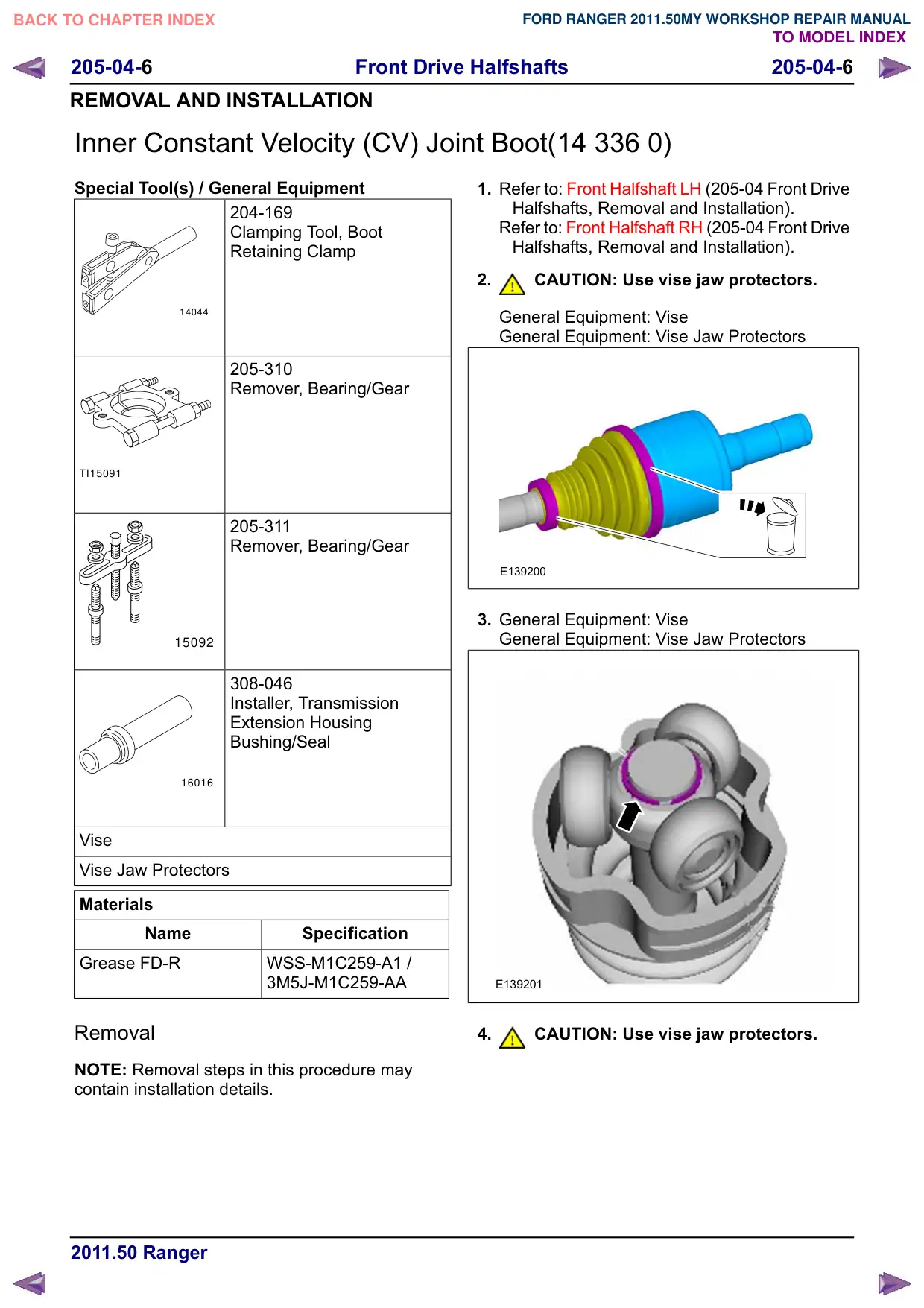
Discard the CV joint boot .
Install the Special Tool(s): 205-310, 205-311
General Equipment: Vise
General Equipment: Vise Jaw Protectors
205-310
205-311
E0001661
Installation
1.
CAUTION: Use vise jaw protectors.
NOTE: Make sure that a new inner constant
velocity (CV) joint boot is installed.
General Equipment: Vise
General Equipment: Vise Jaw Protectors
ELE0019556
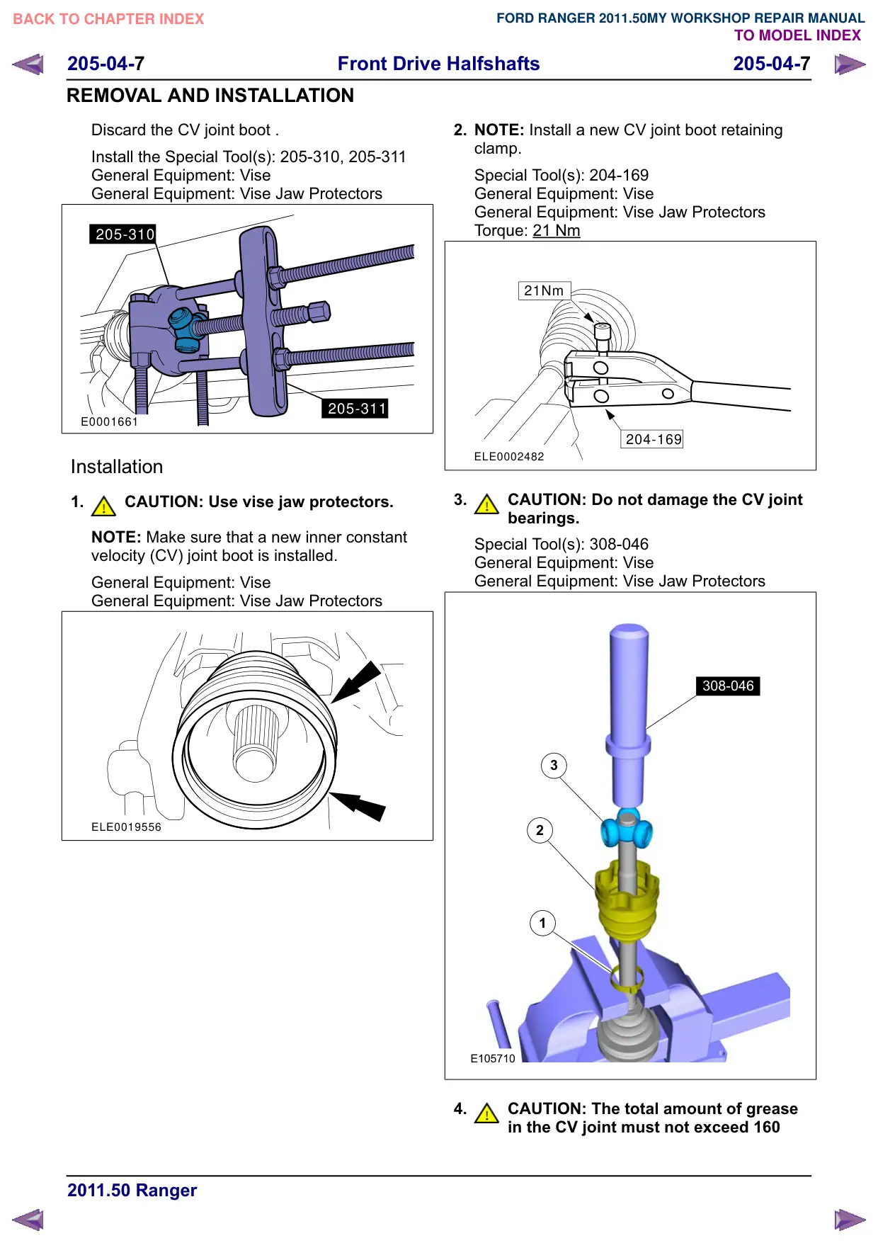
2. NOTE: Install a new CV joint boot retaining
clamp.
Special Tool(s): 204-169
General Equipment: Vise
General Equipment: Vise Jaw Protectors
Torque: 21 Nm
21Nm
204-169
ELE0002482
3.
CAUTION: Do not damage the CV joint
bearings.
Special Tool(s): 308-046
General Equipment: Vise
General Equipment: Vise Jaw Protectors
308-046
308-046
3
2
1
E105710
4.
CAUTION: The total amount of grease
in the CV joint must not exceed 160
Front Drive Halfshafts
205-04-8
205-04-8
REMOVAL AND INSTALLATION
grams for 85 PS vehicles and 255 grams
for 110/130 PS vehicles.
NOTE: Make sure that a new component is
installed.
Material: Grease FD-R (WSS-M1C259-A1 /
3M5J-M1C259-AA) grease
1
2
E105744
5. With the CV joint housing installed, measure
the distance from the inner end of the CV joint
boot to the outer end. The distance needs to be
90 mm.
General Equipment: Vise
General Equipment: Vise Jaw Protectors
1
2
ELM1402510
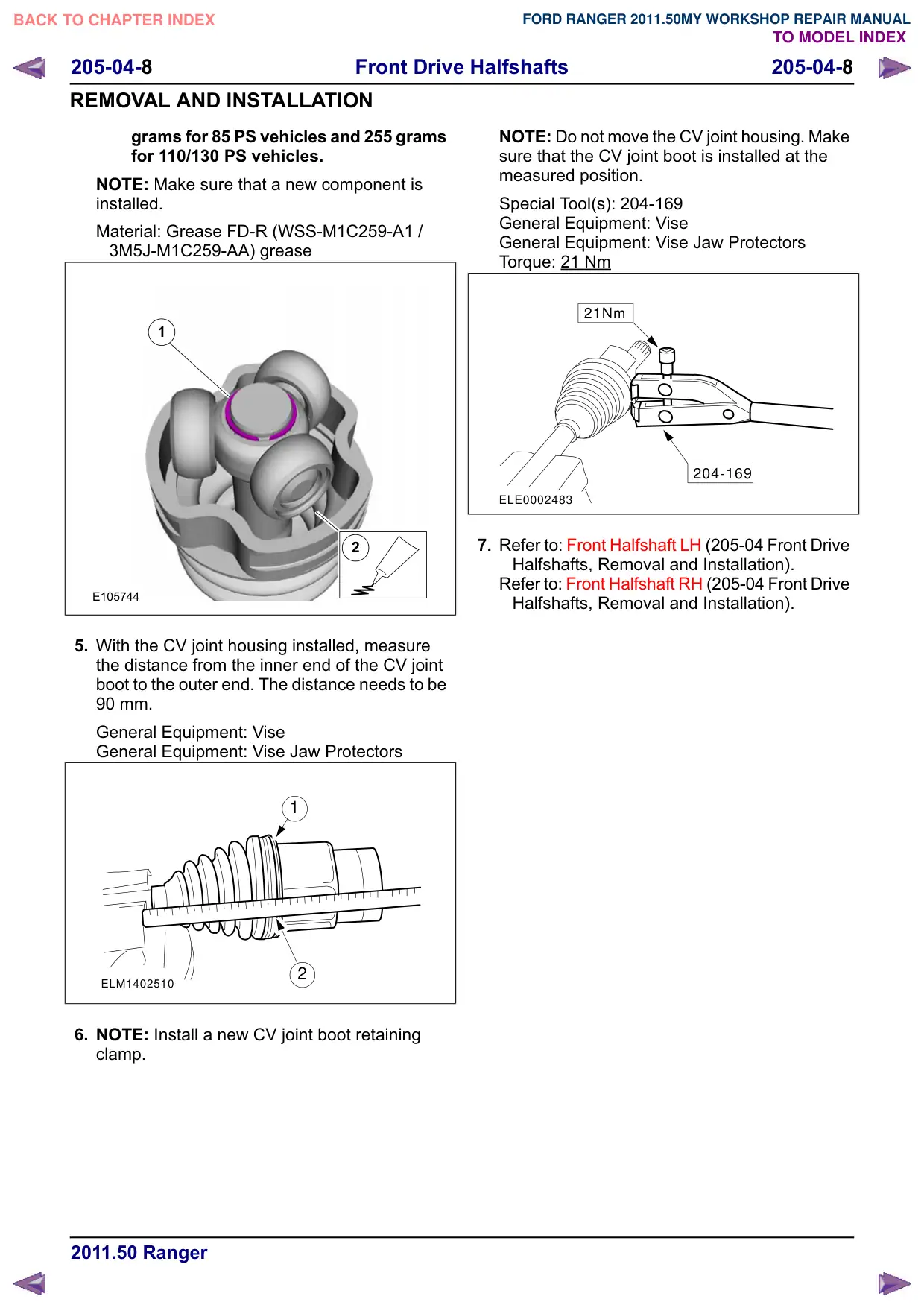
6. NOTE: Install a new CV joint boot retaining
clamp.
NOTE: Do not move the CV joint housing. Make
sure that the CV joint boot is installed at the
measured position.
Special Tool(s): 204-169
General Equipment: Vise
General Equipment: Vise Jaw Protectors
Torque: 21 Nm
21Nm
204-169
ELE0002483
7. Refer to: Front Halfshaft LH (205-04 Front Drive
Halfshafts, Removal and Installation).
Refer to: Front Halfshaft RH (205-04 Front Drive
Halfshafts, Removal and Installation).
Front Drive Halfshafts
205-04-
205-04-
REMOVAL AND INSTALLATION
Outer Constant Velocity (CV) Joint Boot(14 338 0)
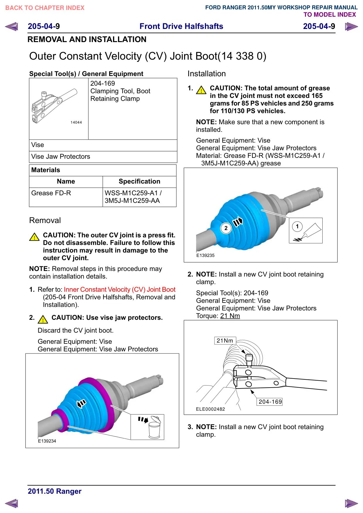
Special Tool(s) / General Equipment
204-169
Clamping Tool, Boot
Retaining Clamp
14044
Vise
Vise Jaw Protectors
Materials
Name
Specification
Grease FD-R
WSS-M1C259-A1 /
3M5J-M1C259-AA
Removal
CAUTION: The outer CV joint is a press fit.
Do not disassemble. Failure to follow this
instruction may result in damage to the
outer CV joint.
NOTE: Removal steps in this procedure may
contain installation details.
1. Refer to: Inner Constant Velocity (CV) Joint Boot
(205-04 Front Drive Halfshafts, Removal and
Installation).
2.
CAUTION: Use vise jaw protectors.
Discard the CV joint boot.
General Equipment: Vise
General Equipment: Vise Jaw Protectors
E139234
Installation
1.
CAUTION: The total amount of grease
in the CV joint must not exceed 165
grams for 85 PS vehicles and 250 grams
for 110/130 PS vehicles.
NOTE: Make sure that a new component is
installed.
General Equipment: Vise
General Equipment: Vise Jaw Protectors
Material: Grease FD-R (WSS-M1C259-A1 /
3M5J-M1C259-AA) grease
1
2
E139235
2. NOTE: Install a new CV joint boot retaining
clamp.
Special Tool(s): 204-169
General Equipment: Vise
General Equipment: Vise Jaw Protectors
Torque: 21 Nm
21Nm
204-169
ELE0002482
3. NOTE: Install a new CV joint boot retaining
clamp.
Front Drive Halfshafts
205-04-10
205-04-10
REMOVAL AND INSTALLATION
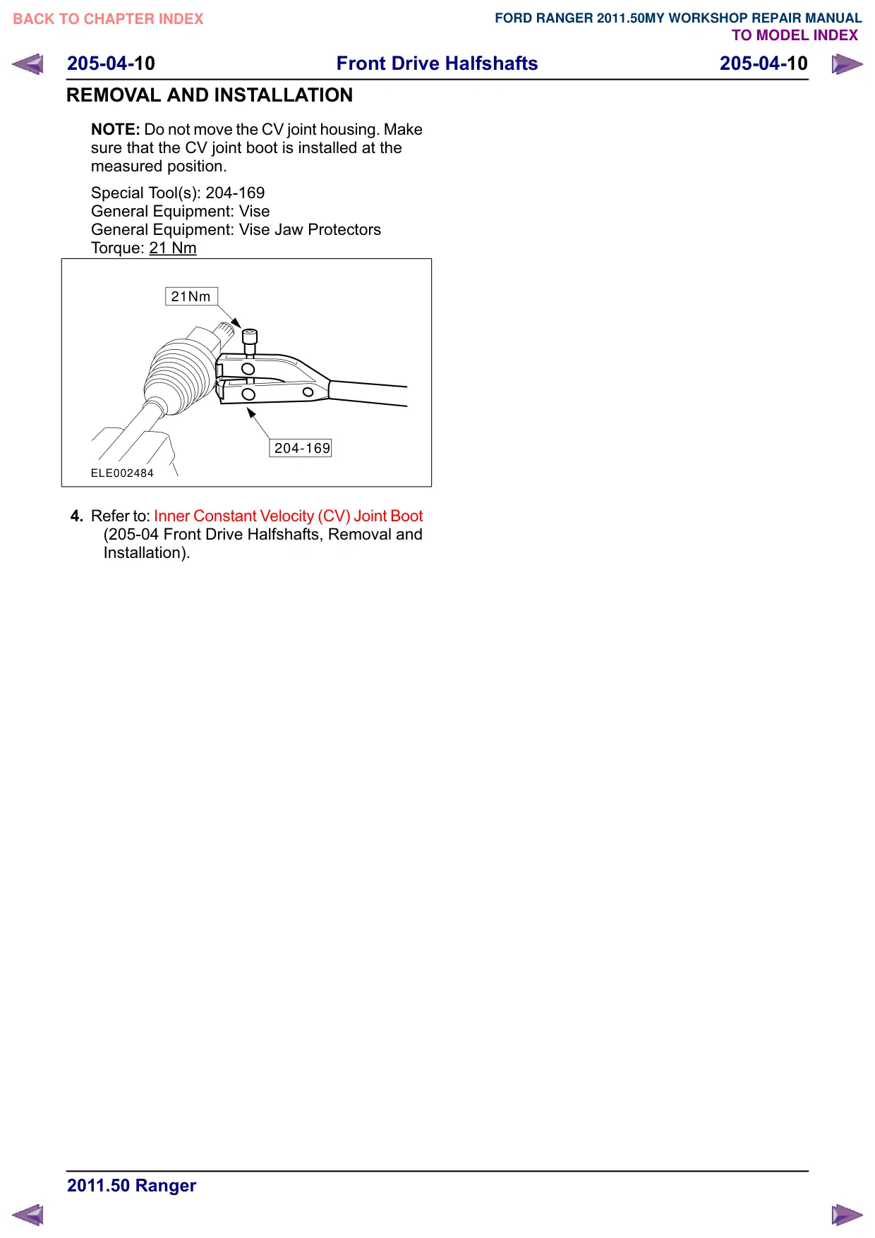
NOTE: Do not move the CV joint housing. Make
sure that the CV joint boot is installed at the
measured position.
Special Tool(s): 204-169
General Equipment: Vise
General Equipment: Vise Jaw Protectors
Torque: 21 Nm
21Nm
204-169
ELE002484
4. Refer to: Inner Constant Velocity (CV) Joint Boot
(205-04 Front Drive Halfshafts, Removal and
Installation).