Coifa da junta homocinética interna (CV)
Inner Constant Velocity (CV) Joint Boot
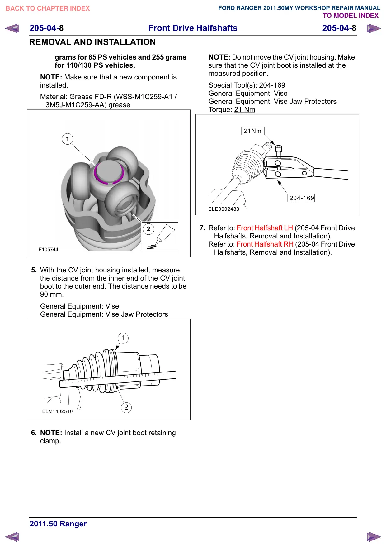
Texto da página
Link desta página: https://ranger.mbrace.com.br/oficina/154
Imagem: https://ranger.mbrace.com.br/img/oficina/154.webp
Front Drive Halfshafts
205-04-8
205-04-8
REMOVAL AND INSTALLATION
grams for 85 PS vehicles and 255 grams
for 110/130 PS vehicles.
NOTE: Make sure that a new component is
installed.
Material: Grease FD-R (WSS-M1C259-A1 /
3M5J-M1C259-AA) grease
1
2
E105744
5. With the CV joint housing installed, measure
the distance from the inner end of the CV joint
boot to the outer end. The distance needs to be
90 mm.
General Equipment: Vise
General Equipment: Vise Jaw Protectors
1
2
ELM1402510
6. NOTE: Install a new CV joint boot retaining
clamp.
NOTE: Do not move the CV joint housing. Make
sure that the CV joint boot is installed at the
measured position.
Special Tool(s): 204-169
General Equipment: Vise
General Equipment: Vise Jaw Protectors
Torque: 21 Nm
21Nm
204-169
ELE0002483
7. Refer to: Front Halfshaft LH (205-04 Front Drive
Halfshafts, Removal and Installation).
Refer to: Front Halfshaft RH (205-04 Front Drive
Halfshafts, Removal and Installation).