418-00-1
Module Communications Network
418-00-1
.
SECTION 418-00 Module Communications Network
VEHICLE APPLICATION: 2011.50 Ranger
CONTENTS
DESCRIPTION AND OPERATION
Communications Network (Component Location)..............................................................
Communications Network (Overview)................................................................................
Network components......................................................................................................
Controller area network (CAN).......................................................................................
Advantages of a network................................................................................................
The layout of the network...............................................................................................
Network areas with high and low data transfer rates......................................................
Data transfer rates..........................................................................................................
Terminating resistor........................................................................................................
Controller Area Network (CAN) Standard.......................................................................
The lines CAN H and CAN L..........................................................................................
Priority.............................................................................................................................
Two message types........................................................................................................
Compatibility...................................................................................................................
Configurations.................................................................................................................
Error management in the Controller Area Network (CAN)..............................................
No communications from the module.............................................................................
Faulty communications...................................................................................................
Local Interconnect Network (LIN)...................................................................................
PAGE
418-00-2
418-00-3
418-00-4
418-00-4
418-00-4
418-00-5
418-00-5
418-00-5
418-00-6
418-00-6
418-00-6
418-00-7
418-00-7
418-00-8
418-00-8
418-00-8
418-00-8
418-00-8
418-00-9
418-00-2
Module Communications Network
418-00-2
DESCRIPTION AND OPERATION
Communications Network œ Component Location
Information not available at this time.
418-00-4
Module Communications Network
418-00-4
DESCRIPTION AND OPERATION
Item
Description
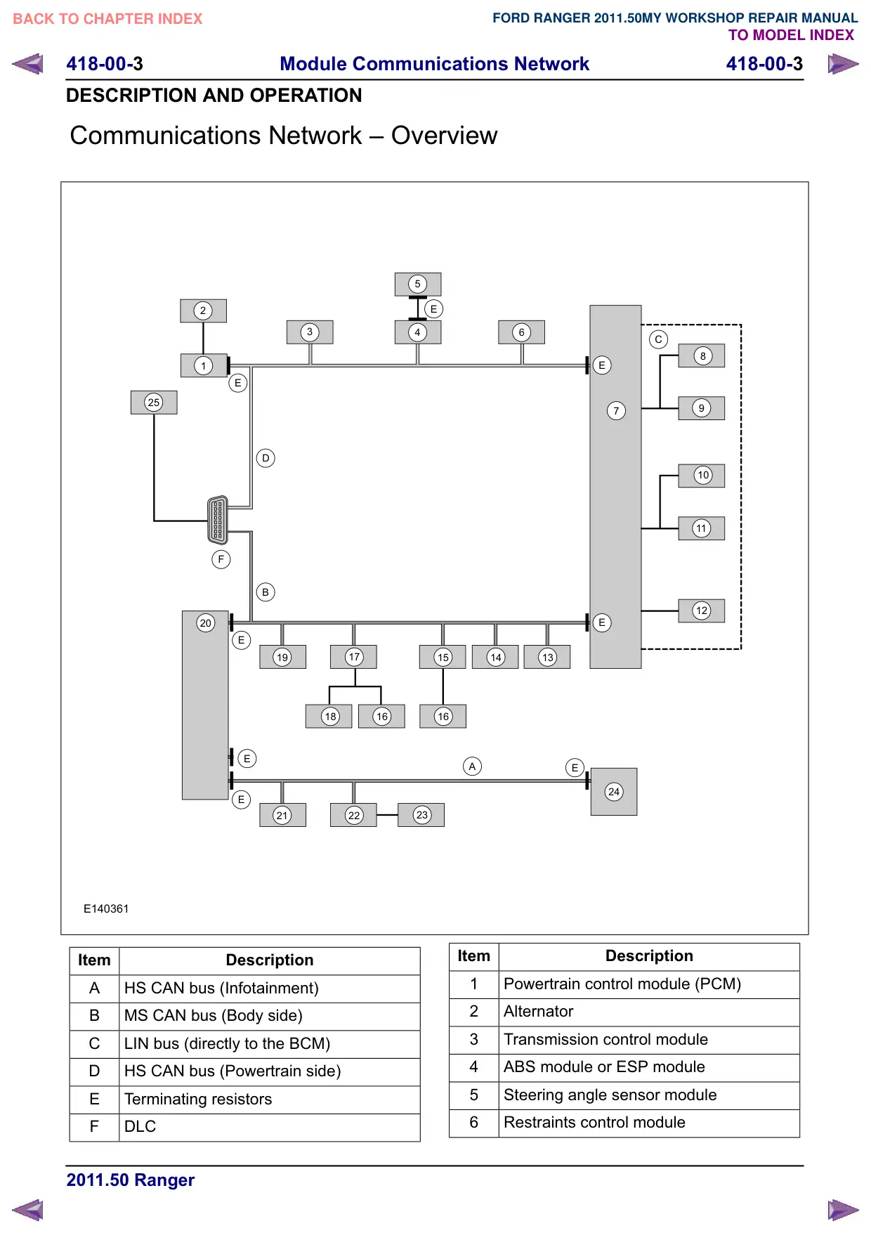
7
Body control module (BCM)
8
Battery monitoring system
Rain sensor
10
Battery backed sounder
11
Interior motion sensor
12
Electric booster heater
13
Trailer module
14
Parking assist control module
15
Passenger front door module
16
Rear door module
Network components
Dependent on the vehicle accessories version, two
data bus systems are used:
Controller Area Network (CAN) bus
Local Interconnect Network (LIN) bus
Due to the increased number of modules and the
resulting continued increase in data transfer, three
different CAN bus systems are used. Essentially,
they only differ in terms of their data transmission
rates and application areas. In order to be able to
distinguish between the individual CAN bus
systems, the CAN bus system with the higher data
transfer rate is referred to as the high-speed (HS)
CAN bus, the CAN bus system(s) with the lower
data transfer rate as the mid-speed (MS) CAN bus
or multimedia (MM) CAN bus. The latter operate
at a slower speed and are used primarily for
communications in comfort electronics. Two
interfaces (gateways) are used in order to
exchange data between the HS CAN bus, MS CAN
bus and the MM CAN bus. These provide the
connection between the three CAN databus
systems and are installed in the BCM and in the
electronic instrument cluster.
The number of modules which are connected to
the three databus systems depends on the
equipment level of the vehicle.
Controller area network (CAN)
General
In the past, a separate cable was needed for every
command and every message. The use of
Item
Description
17
Driver front door module
18
Multi-power window switch pack
19
Dual zone electronic temperature control
20
Instrument panel cluster
21
Bluetooth/Voice control
22
Multifunction display/Navigation
multifunction display
23
Integrated control panel
24
Audio head unit
25
Tracking and blocking module
networks has enabled an increase in functionality
without additional cables.
The demand for greater functionality in vehicles,
both due to legal requirements and in order to meet
customer demands, results in increasing complexity
of vehicle systems.
The Controller Area Network (CAN) was developed
as part of the effort to achieve greater flexibility of
the electrical systems. It allows a large number of
different control commands and messages to be
sent and received on the same cable system.
The number of control commands and messages
which can be processed by a network depends on
factors like the data transfer rate and the length of
the messages. The SMAX/Galaxy network, which
is based on a Controller Area Network (CAN), is
capable of transferring over 500 different signals
and approx. 100 messages. These messages are
also described as transmission blocks and may
contain several signals.
Advantages of a network
Easy integration of additional functions and
DFFHVVRULHV
As the control modules in the network are already
connected to each other and can easily accept
further information, only the following steps are
necessary:
418-00-5
Module Communications Network
418-00-5
DESCRIPTION AND OPERATION
Connection of the sensors to the nearest control
module
Connection of the component which is to be
actuated to the nearest control module
Software-based adaptation of the module
configuration
This means that the overall length of cabling and
the number of components in a vehicle are reduced
compared to before.
One example of this is the integration of the speed
control system.
Before the introduction of the network, control
modules, switches, vacuum pumps, vacuum
servos, hoses and wiring harnesses were needed
for this system.
Following introduction of the network, only one
switch and the software for adaptation of the
vehicle configuration are required.
Easier to introduce logical functions
The term "logical functions" is used to describe the
concept whereby certain events trigger certain
responses. For example, the system is
programmed in such a way that if a tail lamp fails
a message is sent via the Controller Area Network
(CAN) to the electronic instrument cluster to warn
the driver.
A logical function can be introduced by merely
reprogramming the affected control modules. In
the above case this would be the body control
module (BCM) and the electronic instrument
cluster. The number of components and cables
remains the same.
Simple adaptation of systems to customer
demands and market requirements
Vehicle functions can be adapted to customer
demands and market requirements, e.g. in the case
of the rear fog lamps. In some countries two rear
fog lamps are used, whereas in other countries
only one fog lamp is used on the driver's side. In
the past it was necessary to stock different spare
parts for different markets. Now a single part is
sufficient to cover all markets - it just needs to be
programmed for the specific market.
Use of similar basic systems for entire series
Similar networks (hardware) can be used for a wide
variety of different vehicles.
The vehicles only differ in terms of:
The individual components (modules, sensors,
actuated components etc.) which are connected
to the system.
The task(s) of the components.
The definition of the components as
standard/optional/accessories.
The configuration/programming of the system.
The layout of the network.
General
The network is made up of a range of control
modules (these are also referred to as nodes)
which are connected to each other via two
communication cables. Each module has its own
voltage supply and ground connection and receives
messages and control commands via both
communication cables.
In the event of a break in the circuit, the modules
beyond the break cannot communicate with other
parts of the network.
Network areas with high and low data
transfer rates
The network consists of two parts. The area with
the higher data transfer rate (HS CAN bus)
transmits signals and messages between the body
control module (BCM) and control modules which
are mostly located in the engine compartment. The
area with the lower data transfer rate (MS/MM CAN
bus) transmits signals and messages between the
body control module (BCM) and the control
modules in the passenger compartment and in the
luggage compartment.
The body control module (BCM) represents the
interface between the two areas and converts the
data transfer rate up or down to allow the two areas
of the network to communicate with each other.
Data transfer rates
The Controller Area Network (CAN) uses two data
transfer rates.
The HS/MM CAN bus (high data transfer rate)
transfers data at a rate of 500 kBit/s.
The MS CAN bus (low data transfer rate)
transfers data at a rate of 125 kBit/s. 1 kBit/s
1024 Bit per second (1 Byte 8 Bit).
418-00-6
Module Communications Network
418-00-6
DESCRIPTION AND OPERATION
Terminating resistor
In order to avoid reflections and interferences in
the CAN bus network, a terminating resistor is
provided for bridging purposes at both ends of the
CAN. Each terminating resistor has a resistance
value of 120 Ohm.
For the HS CAN bus, the terminating resistors
are located in the body control module (BCM)
and in the powertrain control module (PCM).
For the MS/MM CAN bus, the terminating
resistors are located in the body control module
(BCM) and in the electronic instrument cluster.
The two resistors are connected in parallel. The
resistance values are as follows:
When the CAN bus is intact, the resistance is
approx. 60 Ohm in both areas of the network.
In the event of a short circuit between the
communication lines the resistance is approx.
0 Ohm.
Controller Area Network (CAN) Standard
General
The CAN bus is a standardized system for
multiplex communication. This means that multiple
control modules can use the same wires for
communication without causing interference
between the different signals.
The Controller Area Network (CAN) Standard
specifies the following:
The use of two wires (CAN H and CAN L)
The voltage amplitudes
The structure of the messages
The way in which transmission faults are
handled
The lines CAN H and CAN L
The lines CAN H and CAN L must not be confused
with the different data transfer rates HS CAN bus
and HS CAN bus. The lines CAN H and CAN L are
the paths on which signals are transmitted within
the multiplex communication system.
Communications take place at different voltages
via two separate wires which are twisted in pairs.
As a result, the network is less susceptible to
interference.
The same message is put out at the same time on
both wires with different voltages.
Binary signal 0 2.5V on CAN H and on CAN
/
Binary signal 1 4V on CAN H and 1V on CAN
/
The average potential difference between CAN L
and ground is approx. 2.3V, or approx. 2.8V
between CAN H and ground.
These measured values refer to "normal"
communications in the Controller Area Network
(CAN), i.e. cases in which no faults have occurred
which would cause the modules to send out error
messages.
NOTE: Certain modules, such as the restraints
control module (the module for the SRS system)
and the ABS module or ESP module communicate
with their relevant sensors via a so-called internal
CAN bus. The internal CAN bus systems have
nothing to do with the communications on the
general CAN bus. Instead, they are only used for
the purpose of transmitting data between sensors
and associated modules.
418-00-7
Module Communications Network
418-00-7
DESCRIPTION AND OPERATION
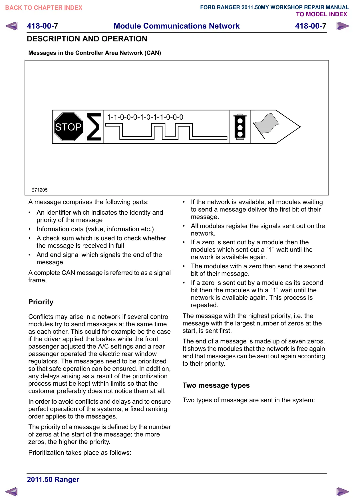
Messages in the Controller Area Network (CAN)
E71205
A message comprises the following parts:
An identifier which indicates the identity and
priority of the message
Information data (value, information etc.)
A check sum which is used to check whether
the message is received in full
And end signal which signals the end of the
message
A complete CAN message is referred to as a signal
frame.
Priority
Conflicts may arise in a network if several control
modules try to send messages at the same time
as each other. This could for example be the case
if the driver applied the brakes while the front
passenger adjusted the A/C settings and a rear
passenger operated the electric rear window
regulators. The messages need to be prioritized
so that safe operation can be ensured. In addition,
any delays arising as a result of the prioritization
process must be kept within limits so that the
customer preferably does not notice them at all.
In order to avoid conflicts and delays and to ensure
perfect operation of the systems, a fixed ranking
order applies to the messages.
The priority of a message is defined by the number
of zeros at the start of the message; the more
zeros, the higher the priority.
Prioritization takes place as follows:
If the network is available, all modules waiting
to send a message deliver the first bit of their
message.
All modules register the signals sent out on the
network.
If a zero is sent out by a module then the
modules which sent out a "1" wait until the
network is available again.
The modules with a zero then send the second
bit of their message.
If a zero is sent out by a module as its second
bit then the modules with a "1" wait until the
network is available again. This process is
repeated.
The message with the highest priority, i.e. the
message with the largest number of zeros at the
start, is sent first.
The end of a message is made up of seven zeros.
It shows the modules that the network is free again
and that messages can be sent out again according
to their priority.
Two message types
Two types of message are sent in the system:
418-00-8
Module Communications Network
418-00-8
DESCRIPTION AND OPERATION
Periodic signal frames are sent regularly to
indicate the current status of a parameter. They
are used for types of information which change
frequently, e.g. vehicle speed signals.
Event-related signal frames are only sent if
certain conditions are met. They are used for
types of information which occur more rarely,
e.g. the opening or closing of a window.
The messages may also incorporate an update bit
which shows how "new" the message is.
The system always assumes that the messages
reach the intended recipient, so no receipt
acknowledgement signals are sent out. Replies
are only sent in response to direct queries from
other modules.
However, a receiver module also knows how often
it should receive a particular status message. If the
message is not received then the receiver module
can launch an emergency running program and/or
set a trouble code (DTC).
Compatibility
The modules must all speak the same language
and be compatible with each other. As a result, a
standardized communication protocol is used.
The language of the modules is contained in the
signal configuration. If the signal configuration of
a module does not match the configuration of the
other modules than the module cannot
communicate with them. This means that all
modules must have a compatible signal
configuration.
In order to check this, the body control module
(BCM) sends out an identification number for its
signal configuration via the Controller Area Network
(CAN). The other modules compare this number
to their own number. If the identification does not
match then the module stores a trouble code
(DTC). The signal configuration is changed
occasionally, so that new messages are added
and old ones are removed.
Configurations
The following information is downloaded when a
system is configured:
Type of control modules contained (e.g. body
control module (BCM)) - task assignments for
the individual modules (e.g. this is the module
for the driver's door))
Functions contained (e.g. alarm function on or
off)
Connected components (e.g. whether or not the
inclination sensor is relevant for the alarm
function)
Output an input messages for each module
Storage locations for various data
The configuration needs to be adapted for any
accessories which are installed and needs to be
downloaded again if a module is replaced. The
diagnostic unit is used for adaptation and
downloading.
NOTE: Two vehicles which otherwise appear
identical may behave differently if they have
different configurations. Parameters may have
been changed by the customer or by the workshop.
Error management in the Controller Area
Network (CAN)
General
The Controller Area Network (CAN) is monitored
by the body control module (BCM). If the BCM
detects a fault in the CAN bus then a trouble code
(DTC) is stored in the BCM. There are different
types of DTC according to the fault type:
No communications from the module
Faulty communications
No communications from the module
The body control module (BCM) knows which
modules are in the Controller Area Network (CAN)
and checks whether all modules are
communicating. If a module is not communicating
a trouble code (DTC) is set in the BCM. There is
a trouble code (DTC) for every module.
Faulty communications
If the Controller Area Network (CAN) is in operation
then the body control module (BCM) continuously
monitors the flow of information in the network. If
the BCM determines that, for some reason, the
communications in the CAN bus are interrupted, it
can set a trouble code (DTC). The BCM has trouble
codes for all parts of the CAN bus (one each for
the HS CAN bus and the MS/MM CAN bus).
418-00-
Module Communications Network
418-00-
DESCRIPTION AND OPERATION
With the exception of the BCM, which only knows
one type of DTC, each module uses two types of
DTC in relation to communication faults. These
are:
Faulty messages
Faulty configuration
As the BCM is the main module in the network, it
does not have a DTC for faulty configuration.
Faulty messages
The control modules continuously monitor the flow
of information in the Controller Area Network
(CAN). If a module receives a message it cannot
interpret it sends a fault message via the CAN bus.
The modules also have function which allows them
to detect any faulty messages they generate
themselves. This prevents interference on the CAN
bus. If there is a lot of interference in the network
then any modules which cannot communicate
properly can switch themselves off. This status is
referred to as "databus OFF" - the module can no
longer send or receive information.
To prevent the vehicle from coming to a sudden
standstill or suffering a total loss of particular
functions if a fault occurs in the CAN bus, certain
modules have an emergency running mode. This
means that modules which are required for driving
or for safety aspects (e.g. the powertrain control
module (PCM) or the transmission control module
(TCM)) can maintain a restricted functionality on
the basis of predefined or estimated data. For
example, if communications to the transmission
control module (TCM) are interrupted then the
transmission will use a preselected gear which will
enable the customer to at least drive to the nearest
workshop.
A module remains in "databus OFF" mode until the
power supply to the module is switched off, or a
module determines that the "databus OFF"
condition no longer exists. If the power supply is
reconnected the module attempts to re-establish
communications.
Faulty configuration
The body control module (BCM) transmits its
configuration ID within the messages it sends out
to other modules. To enable the modules in the
Controller Area Network (CAN) to communicate
with each other they must have the same
configuration ID, as modules only look at messages
carrying their own configuration ID. If the signal
configuration of a module does not match the signal
configuration of the BCM then a trouble code (DTC)
is stored in the module with the faulty configuration.
NOTE: A module will save a trouble code (DTC) if
it does not receive any messages from the engine
control module (ECM). This also applies if there
are any software errors in the module. If the circuit
in the Controller Area Network (CAN) is interrupted
then certain modules will also not receive any
messages from the ECM.
NOTE: A module will save a trouble code (DTC) if
it does not receive any messages from the body
control module (BCM). This also applies if there
are any software errors in the module. If the circuit
in the Controller Area Network (CAN) is interrupted
then certain modules will also not receive any
messages from the BCM.
Local Interconnect Network (LIN)
The Local Interconnect Network (LIN) bus is a
standard which has been developed for
cost-effective communications between intelligent
sensors and actuators in motor vehicles. LIN is
used wherever the bandwidth and versatility of
CAN is not required.
The LIN specification comprises the LIN protocol,
a standard format for describing a complete LIN
network and the interface between a LIN network
and the application.
A LIN network is made up of a LIN master and one
or more LIN slaves.
The LIN network utilizes the master/slave principle
for the purpose of bus access control. This has the
significant advantage that few resources (CPU
performance, ROM, RAM) are required for bus
management in the slave module. The master is
implemented in a control module or a gateway
which has the necessary resources. All
communication is initiated by the master.
Consequently, a message always consists of a
header, which is generated by the master, and a
response from the slave.
The data transfer rate is in the region of up to 20
Kbit/s.
The LIN master knows the time sequence of all
data which are to be transmitted. These data are
transmitted by the corresponding LIN slaves (e.g.
ultrasonic sensors) when requested to do so by
the LIN master.
LIN is a single-wire bus, i.e. the data are
transmitted across a single-stranded cable. Usually
the same cable is also used to provide the supply
voltage. The ground connection of the supply
voltage also acts as the ground connection of the