Rede de comunicação – Visão geral
Communications Network œ Overview
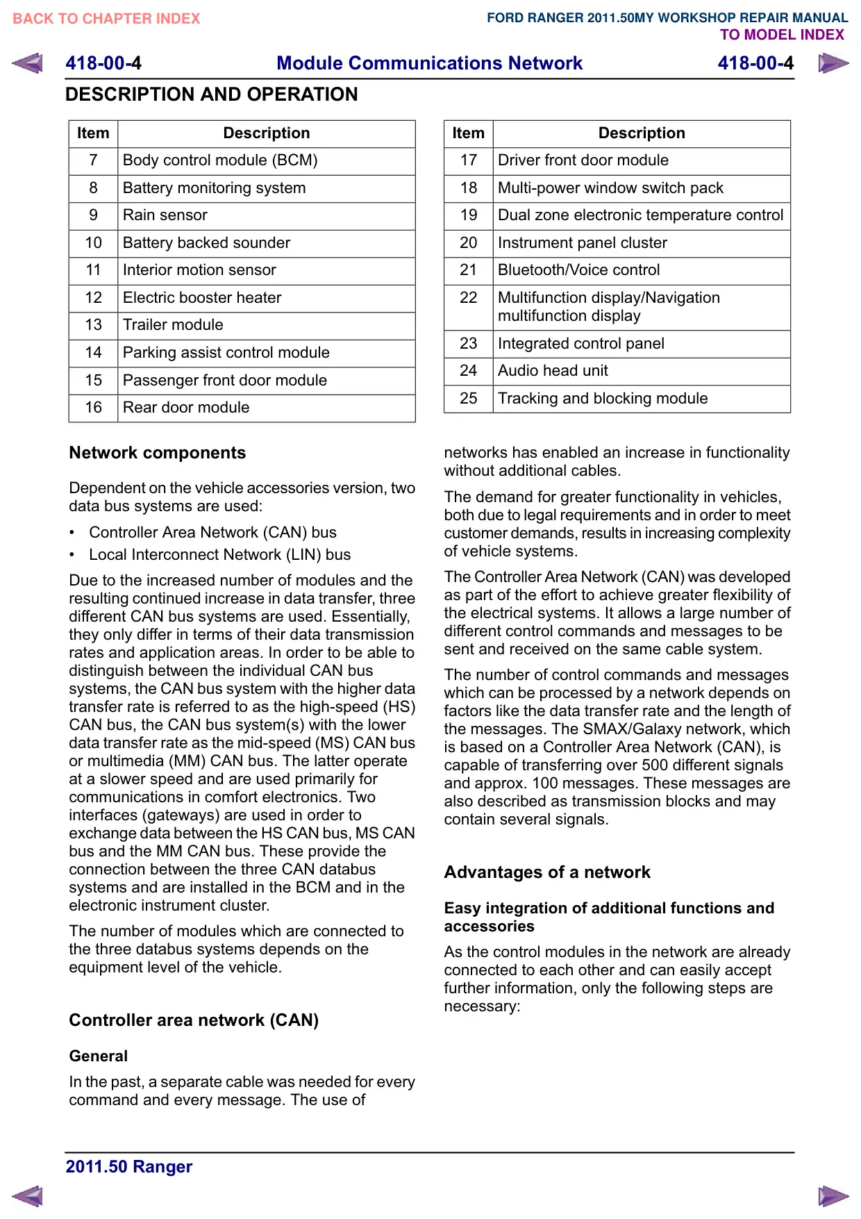
Texto da página
Link desta página: https://ranger.mbrace.com.br/oficina/1291
Imagem: https://ranger.mbrace.com.br/img/oficina/1291.webp
418-00-4
Module Communications Network
418-00-4
DESCRIPTION AND OPERATION
Item
Description
7
Body control module (BCM)
8
Battery monitoring system
Rain sensor
10
Battery backed sounder
11
Interior motion sensor
12
Electric booster heater
13
Trailer module
14
Parking assist control module
15
Passenger front door module
16
Rear door module
Network components
Dependent on the vehicle accessories version, two
data bus systems are used:
Controller Area Network (CAN) bus
Local Interconnect Network (LIN) bus
Due to the increased number of modules and the
resulting continued increase in data transfer, three
different CAN bus systems are used. Essentially,
they only differ in terms of their data transmission
rates and application areas. In order to be able to
distinguish between the individual CAN bus
systems, the CAN bus system with the higher data
transfer rate is referred to as the high-speed (HS)
CAN bus, the CAN bus system(s) with the lower
data transfer rate as the mid-speed (MS) CAN bus
or multimedia (MM) CAN bus. The latter operate
at a slower speed and are used primarily for
communications in comfort electronics. Two
interfaces (gateways) are used in order to
exchange data between the HS CAN bus, MS CAN
bus and the MM CAN bus. These provide the
connection between the three CAN databus
systems and are installed in the BCM and in the
electronic instrument cluster.
The number of modules which are connected to
the three databus systems depends on the
equipment level of the vehicle.
Controller area network (CAN)
General
In the past, a separate cable was needed for every
command and every message. The use of
Item
Description
17
Driver front door module
18
Multi-power window switch pack
19
Dual zone electronic temperature control
20
Instrument panel cluster
21
Bluetooth/Voice control
22
Multifunction display/Navigation
multifunction display
23
Integrated control panel
24
Audio head unit
25
Tracking and blocking module
networks has enabled an increase in functionality
without additional cables.
The demand for greater functionality in vehicles,
both due to legal requirements and in order to meet
customer demands, results in increasing complexity
of vehicle systems.
The Controller Area Network (CAN) was developed
as part of the effort to achieve greater flexibility of
the electrical systems. It allows a large number of
different control commands and messages to be
sent and received on the same cable system.
The number of control commands and messages
which can be processed by a network depends on
factors like the data transfer rate and the length of
the messages. The SMAX/Galaxy network, which
is based on a Controller Area Network (CAN), is
capable of transferring over 500 different signals
and approx. 100 messages. These messages are
also described as transmission blocks and may
contain several signals.
Advantages of a network
Easy integration of additional functions and
DFFHVVRULHV
As the control modules in the network are already
connected to each other and can easily accept
further information, only the following steps are
necessary: