412-01-2
Climate Control
412-01-2
DESCRIPTION AND OPERATION
Air Distribution and Filtering
E129565
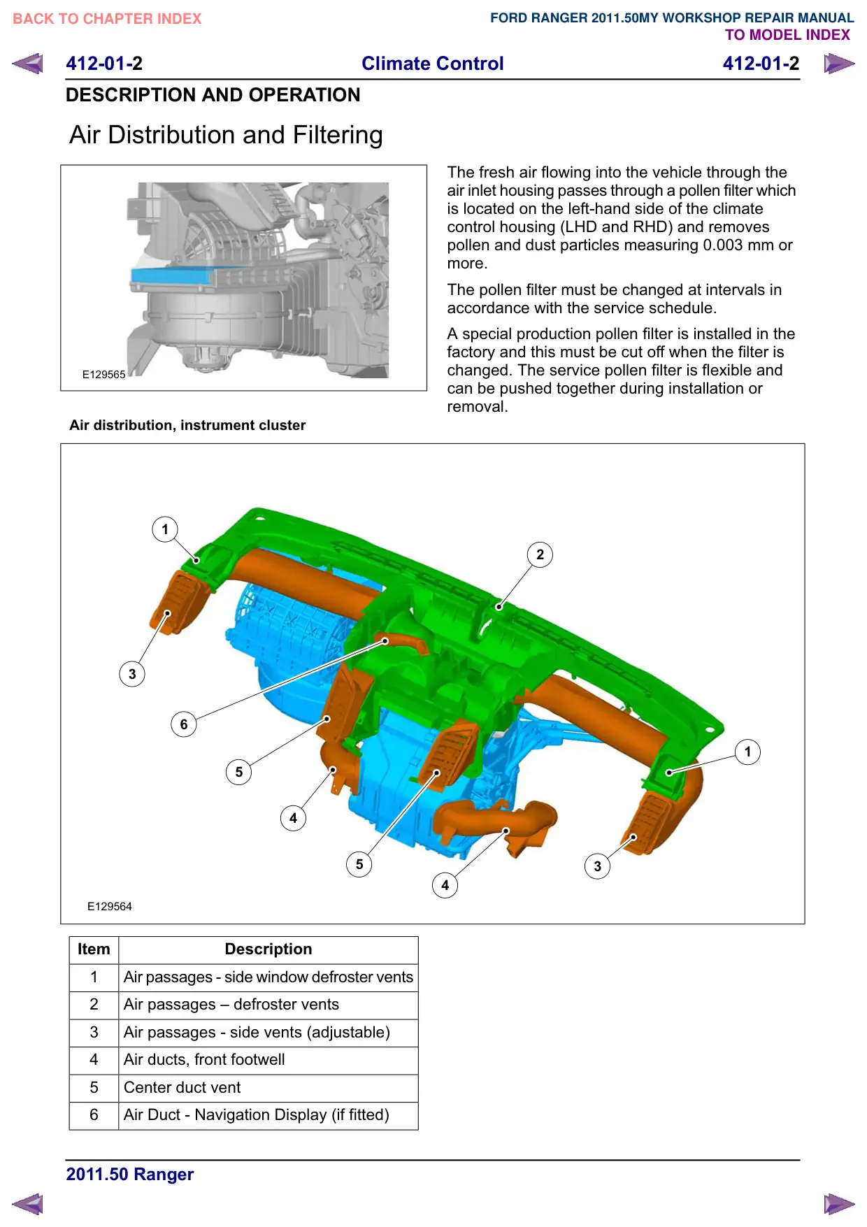
Air distribution, instrument cluster
1
3
6
5
4
5
E129564
Item
Description
1
Air passages - side window defroster vents
2
Air passages œ defroster vents
3
Air passages - side vents (adjustable)
4
Air ducts, front footwell
5
Center duct vent
6
Air Duct - Navigation Display (if fitted)
The fresh air flowing into the vehicle through the
air inlet housing passes through a pollen filter which
is located on the left-hand side of the climate
control housing (LHD and RHD) and removes
pollen and dust particles measuring 0.003 mm or
more.
The pollen filter must be changed at intervals in
accordance with the service schedule.
A special production pollen filter is installed in the
factory and this must be cut off when the filter is
changed. The service pollen filter is flexible and
can be pushed together during installation or
removal.
2
1
3
4
412-01-3
Climate Control
412-01-3
DESCRIPTION AND OPERATION
Heating and Ventilation
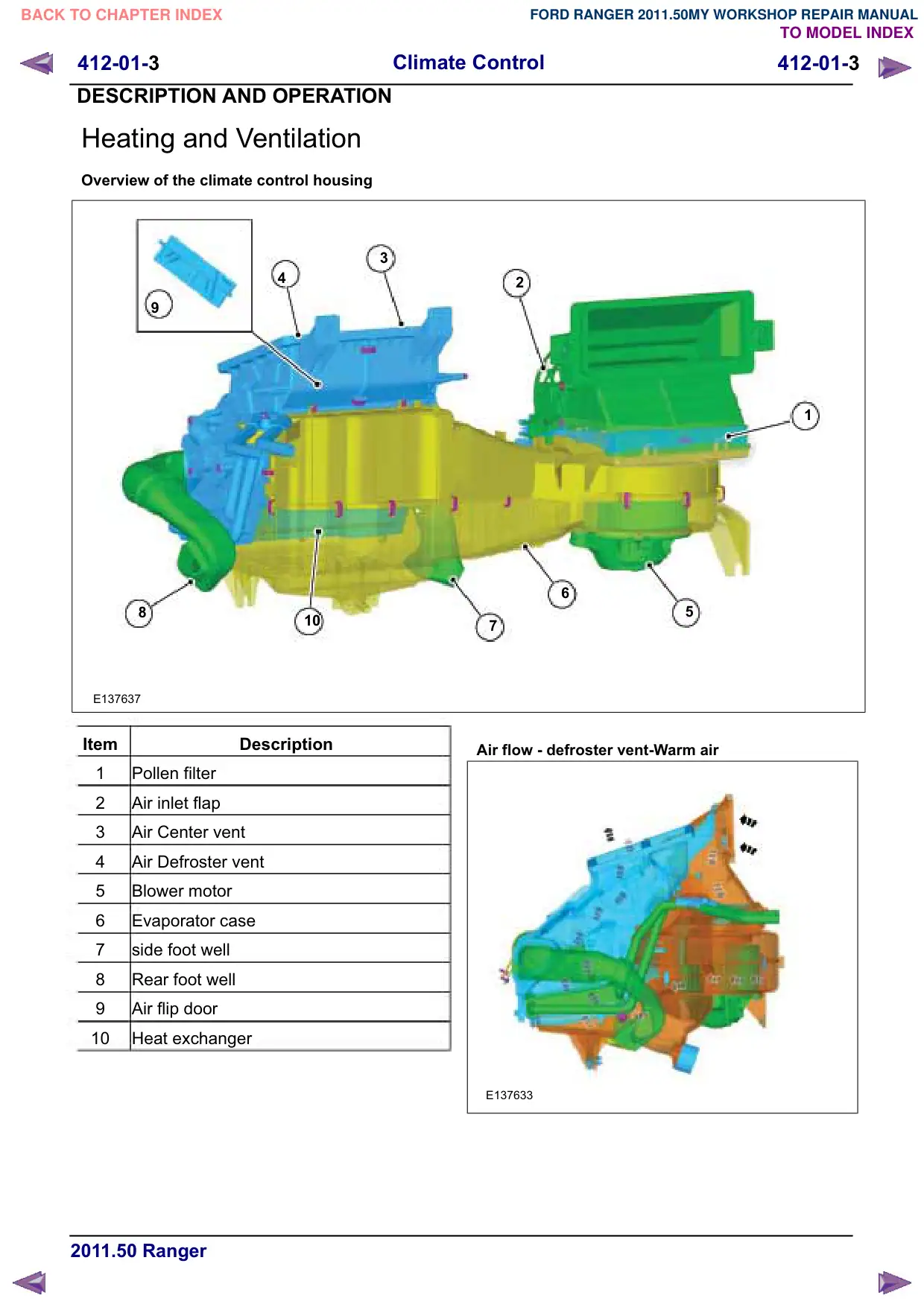
Overview of the climate control housing
3
4
8
10
E137637
Item
Description
1
Pollen filter
2
Air inlet flap
3
Air Center vent
4
Air Defroster vent
5
Blower motor
6
Evaporator case
7
side foot well
8
Rear foot well
Air flip door
10
Heat exchanger
2
1
6
5
7
Air flow - defroster vent-Warm air
E137633
412-01-4
Climate Control
412-01-4
DESCRIPTION AND OPERATION
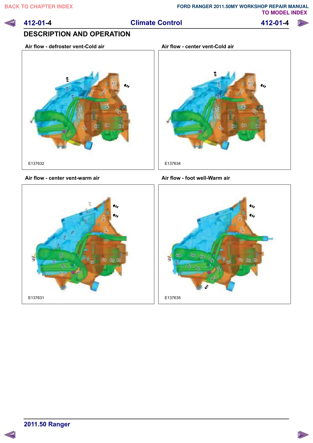
Air flow - defroster vent-Cold air
E137632
Air flow - center vent-warm air
E137631
Air flow - center vent-Cold air
E137634
Air flow - foot well-Warm air
E137635
412-01-6
Climate Control
412-01-6
DESCRIPTION AND OPERATION
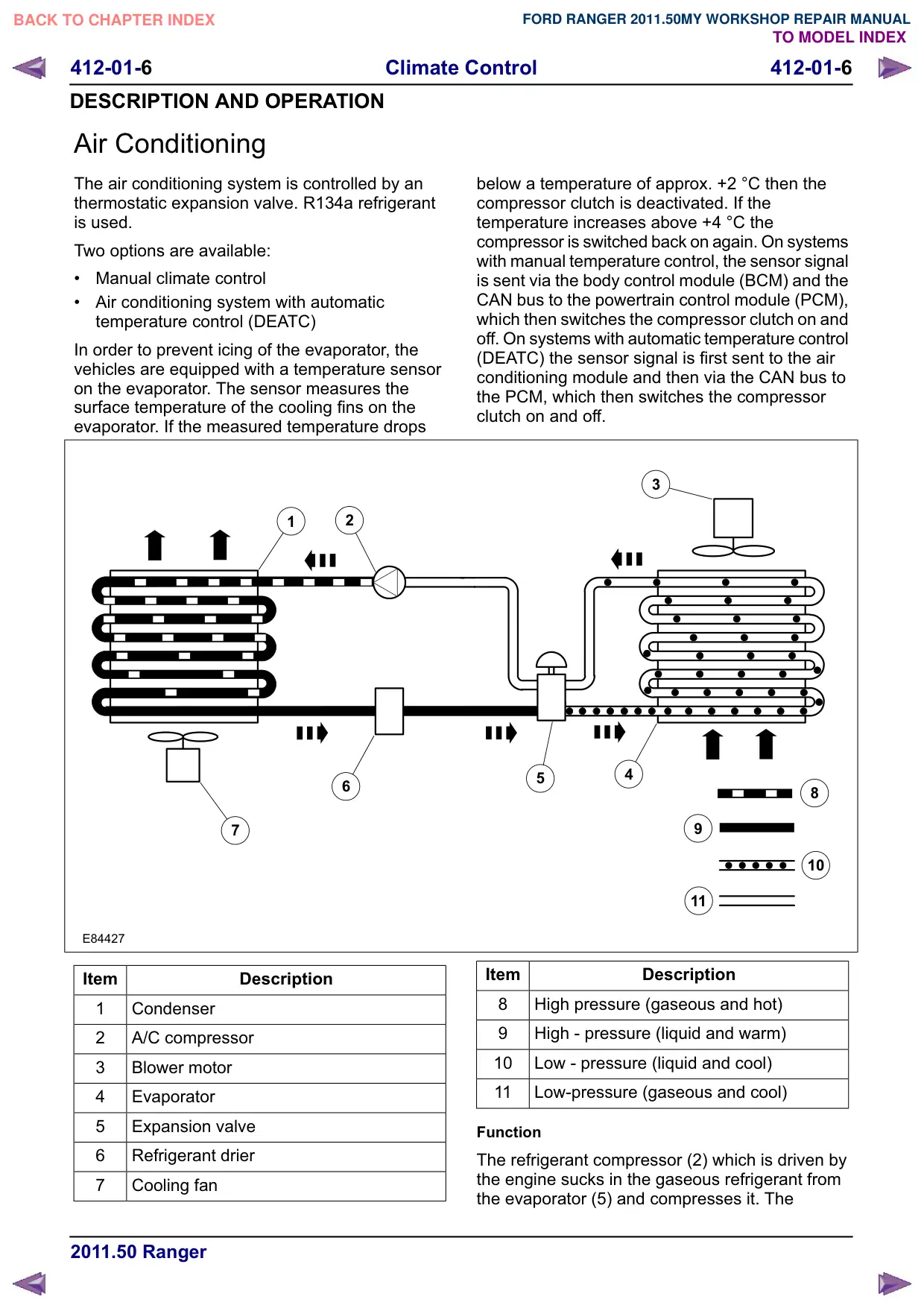
Air Conditioning
The air conditioning system is controlled by an
thermostatic expansion valve. R134a refrigerant
is used.
Two options are available:
Manual climate control
Air conditioning system with automatic
temperature control (DEATC)
In order to prevent icing of the evaporator, the
vehicles are equipped with a temperature sensor
on the evaporator. The sensor measures the
surface temperature of the cooling fins on the
evaporator. If the measured temperature drops
2
1
6
7
E84427
Item
Description
1
Condenser
2
A/C compressor
3
Blower motor
4
Evaporator
5
Expansion valve
6
Refrigerant drier
7
Cooling fan
below a temperature of approx. +2 °C then the
compressor clutch is deactivated. If the
temperature increases above +4 °C the
compressor is switched back on again. On systems
with manual temperature control, the sensor signal
is sent via the body control module (BCM) and the
CAN bus to the powertrain control module (PCM),
which then switches the compressor clutch on and
off. On systems with automatic temperature control
(DEATC) the sensor signal is first sent to the air
conditioning module and then via the CAN bus to
the PCM, which then switches the compressor
clutch on and off.
3
4
5
8
10
11
Item
Description
8
High pressure (gaseous and hot)
High - pressure (liquid and warm)
10
Low - pressure (liquid and cool)
11
Low-pressure (gaseous and cool)
Function
The refrigerant compressor (2) which is driven by
the engine sucks in the gaseous refrigerant from
the evaporator (5) and compresses it. The
412-01-7
Climate Control
412-01-7
DESCRIPTION AND OPERATION
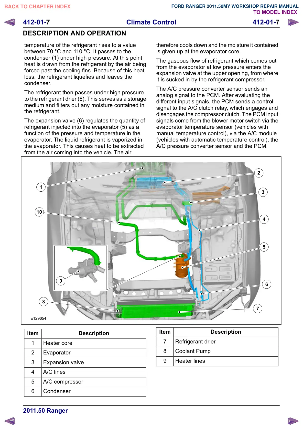
temperature of the refrigerant rises to a value
between 70 °C and 110 °C. It passes to the
condenser (1) under high pressure. At this point
heat is drawn from the refrigerant by the air being
forced past the cooling fins. Because of this heat
loss, the refrigerant liquefies and leaves the
condenser.
The refrigerant then passes under high pressure
to the refrigerant drier (8). This serves as a storage
medium and filters out any moisture contained in
the refrigerant.
The expansion valve (6) regulates the quantity of
refrigerant injected into the evaporator (5) as a
function of the pressure and temperature in the
evaporator. The liquid refrigerant is vaporized in
the evaporator. This causes heat to be extracted
from the air coming into the vehicle. The air
1
10
8
E129654
Item
Description
1
Heater core
2
Evaporator
3
Expansion valve
4
A/C lines
5
A/C compressor
6
Condenser
therefore cools down and the moisture it contained
is given up at the evaporator core.
The gaseous flow of refrigerant which comes out
from the evaporator at low pressure enters the
expansion valve at the upper opening, from where
it is sucked in by the refrigerant compressor.
The A/C pressure converter sensor sends an
analog signal to the PCM. After evaluating the
different input signals, the PCM sends a control
signal to the A/C clutch relay, which engages and
disengages the compressor clutch. The PCM input
signals come from the blower motor switch via the
evaporator temperature sensor (vehicles with
manual temperature control), via the A/C module
(vehicles with automatic temperature control), the
A/C pressure converter sensor and the PCM.
2
3
4
5
6
7
Item
Description
7
Refrigerant drier
8
Coolant Pump
Heater lines
412-01-8
Climate Control
412-01-8
DESCRIPTION AND OPERATION
Electronic refrigerant compressor control valve
E129655
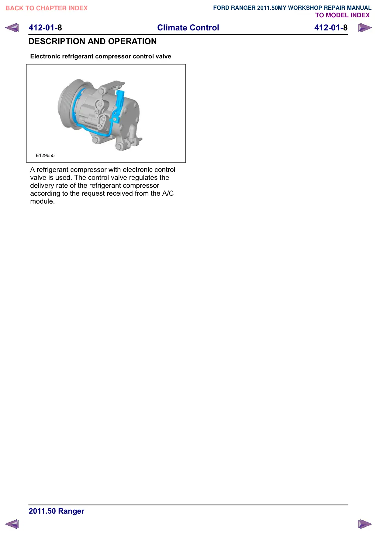
A refrigerant compressor with electronic control
valve is used. The control valve regulates the
delivery rate of the refrigerant compressor
according to the request received from the A/C
module.
412-01-
Climate Control
412-01-
DESCRIPTION AND OPERATION
Control Components
Control assembly, climate control - vehicles with
manual temperature control
E140024
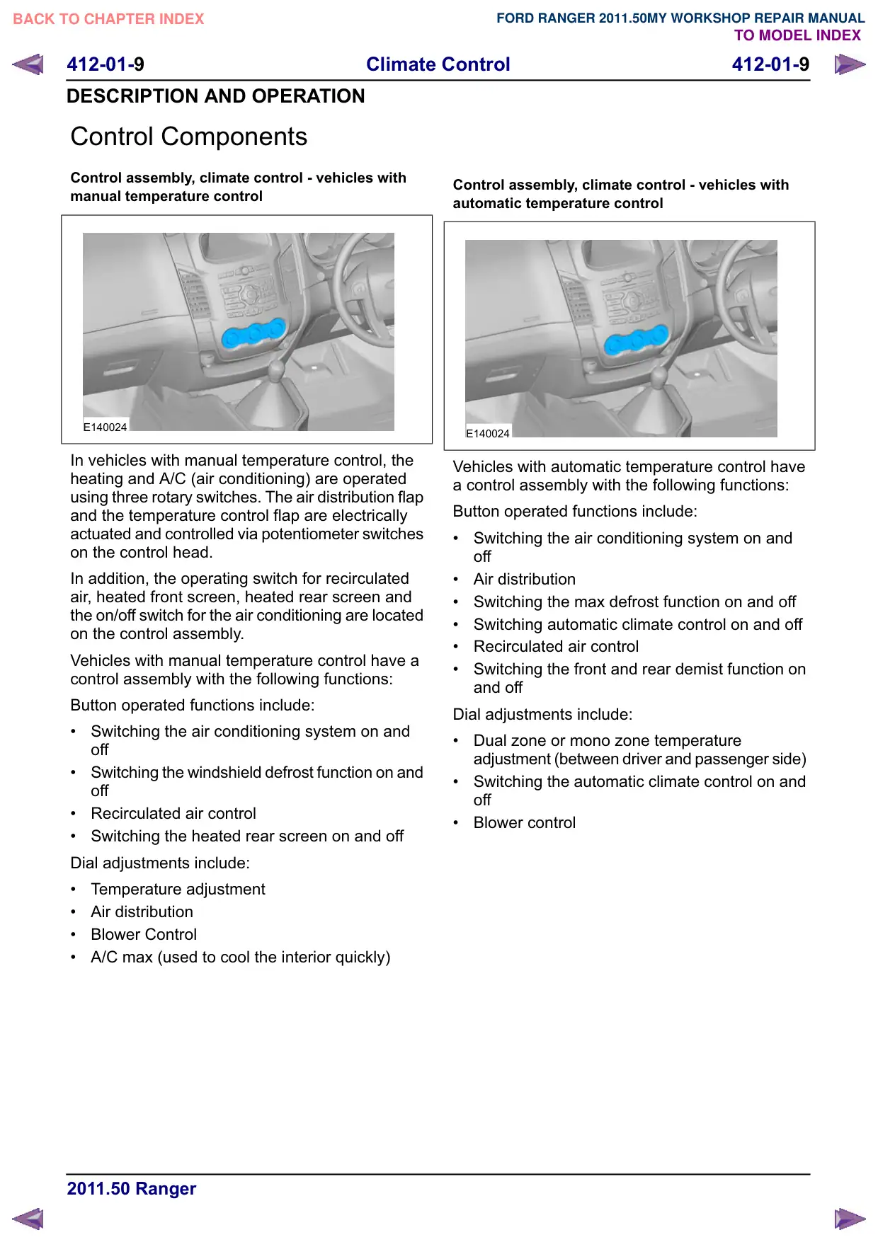
In vehicles with manual temperature control, the
heating and A/C (air conditioning) are operated
using three rotary switches. The air distribution flap
and the temperature control flap are electrically
actuated and controlled via potentiometer switches
on the control head.
In addition, the operating switch for recirculated
air, heated front screen, heated rear screen and
the on/off switch for the air conditioning are located
on the control assembly.
Vehicles with manual temperature control have a
control assembly with the following functions:
Button operated functions include:
Switching the air conditioning system on and
off
Switching the windshield defrost function on and
off
Recirculated air control
Switching the heated rear screen on and off
Dial adjustments include:
Temperature adjustment
Air distribution
Blower Control
A/C max (used to cool the interior quickly)
Control assembly, climate control - vehicles with
automatic temperature control
E140024
Vehicles with automatic temperature control have
a control assembly with the following functions:
Button operated functions include:
Switching the air conditioning system on and
off
Air distribution
Switching the max defrost function on and off
Switching automatic climate control on and off
Recirculated air control
Switching the front and rear demist function on
and off
Dial adjustments include:
Dual zone or mono zone temperature
adjustment (between driver and passenger side)
Switching the automatic climate control on and
off
Blower control
412-01-10
Climate Control
412-01-10
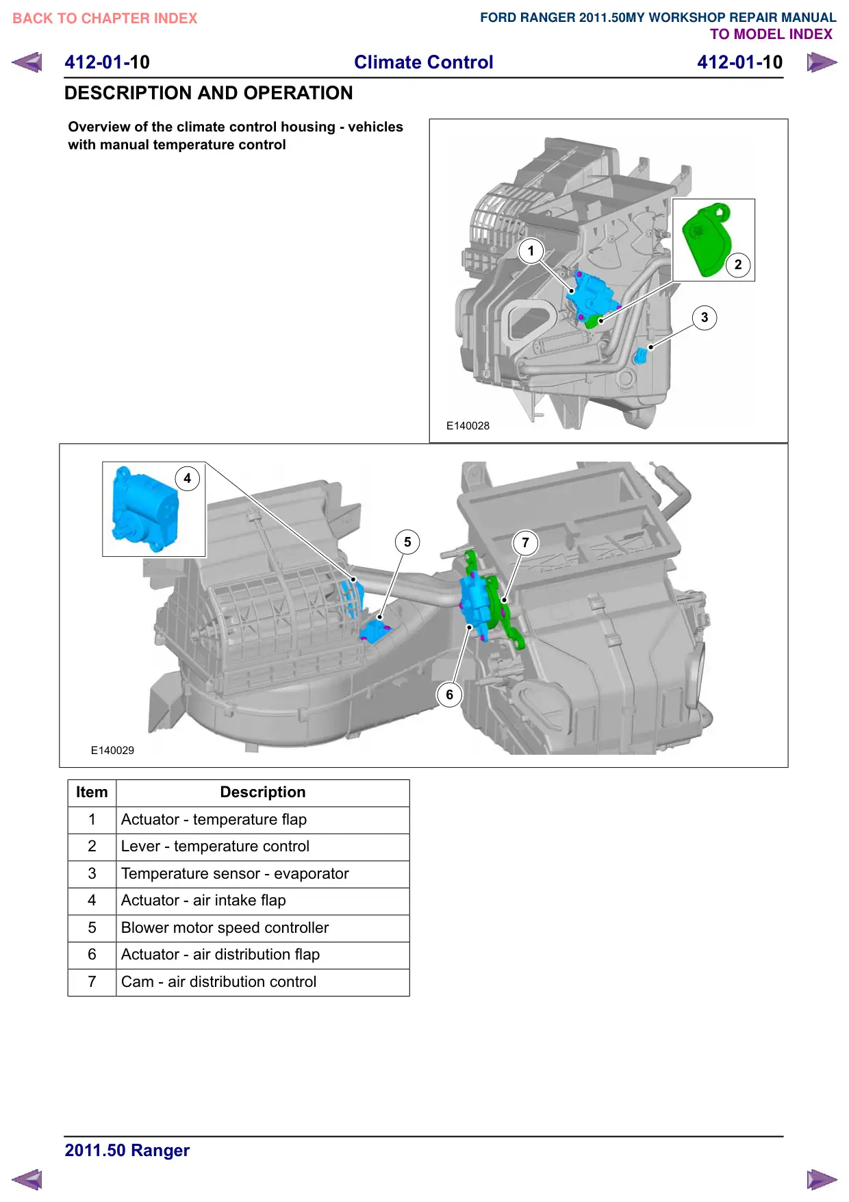
DESCRIPTION AND OPERATION
Overview of the climate control housing - vehicles
with manual temperature control
4
E140029
Item
Description
1
Actuator - temperature flap
2
Lever - temperature control
3
Temperature sensor - evaporator
4
Actuator - air intake flap
5
Blower motor speed controller
6
Actuator - air distribution flap
7
Cam - air distribution control
1
2
3
E140028
5
7
6
412-01-11
Climate Control
412-01-11
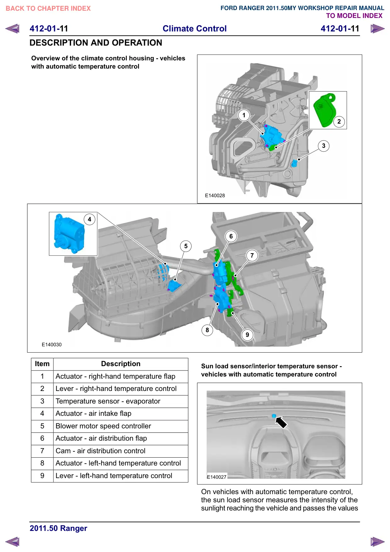
DESCRIPTION AND OPERATION
Overview of the climate control housing - vehicles
with automatic temperature control
4
E140030
Item
Description
1
Actuator - right-hand temperature flap
2
Lever - right-hand temperature control
3
Temperature sensor - evaporator
4
Actuator - air intake flap
5
Blower motor speed controller
6
Actuator - air distribution flap
7
Cam - air distribution control
8
Actuator - left-hand temperature control
Lever - left-hand temperature control
1
2
3
E140028
6
5
7
8
Sun load sensor/interior temperature sensor -
vehicles with automatic temperature control
E140027
On vehicles with automatic temperature control,
the sun load sensor measures the intensity of the
sunlight reaching the vehicle and passes the values
412-01-12
Climate Control
412-01-12
DESCRIPTION AND OPERATION
on to the A/C module. Additionally, the integrated
in-car temperature sensor provides the A/C module
with variable feedback from the cabin. The A/C
module then ensures that the cabin temperature
is regulated to customer comfort.
412-01-13
Climate Control
412-01-13
REMOVAL AND INSTALLATION
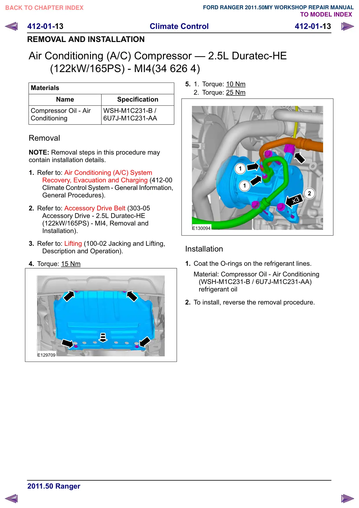
Air Conditioning (A/C) Compressor – 2.5L Duratec-HE
(122kW/165PS) - MI4(34 626 4)
Materials
Name
Specification
Compressor Oil - Air
WSH-M1C231-B /
Conditioning
6U7J-M1C231-AA
Removal
NOTE: Removal steps in this procedure may
contain installation details.
1. Refer to: Air Conditioning (A/C) System
Recovery, Evacuation and Charging (412-00
Climate Control System - General Information,
General Procedures).
2. Refer to: Accessory Drive Belt (303-05
Accessory Drive - 2.5L Duratec-HE
(122kW/165PS) - MI4, Removal and
Installation).
3. Refer to: Lifting (100-02 Jacking and Lifting,
Description and Operation).
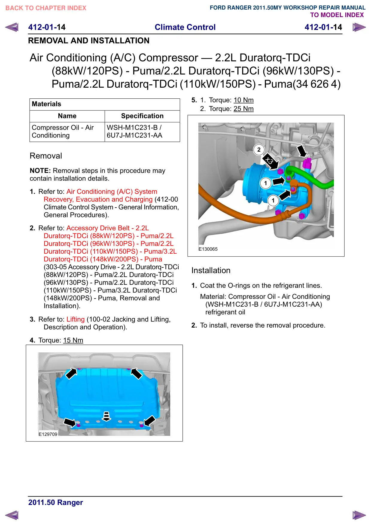
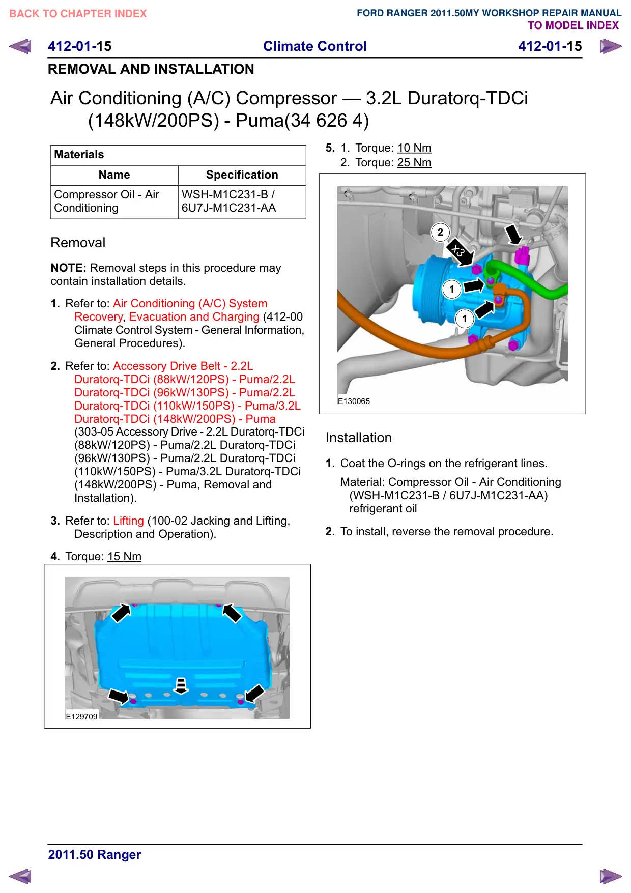
4. Torque: 15 Nm
E129709
5.
1.
Torque: 10 Nm
2. Torque: 25 Nm
1
1
2
x3
E130094
Installation
1. Coat the O-rings on the refrigerant lines.
Material: Compressor Oil - Air Conditioning
(WSH-M1C231-B / 6U7J-M1C231-AA)
refrigerant oil
2. To install, reverse the removal procedure.
412-01-16
Climate Control
412-01-16
REMOVAL AND INSTALLATION
Air Conditioning (A/C) Pressure Sensor
Materials
Name
Specification
Compressor Oil - Air
WSH-M1C231-B /
Conditioning
6U7J-M1C231-AA
Removal
NOTE: Removal steps in this procedure may
contain installation details.
1. Refer to: Air Conditioning (A/C) System Health
and Safety Precautions (100-00 General
Information, Description and Operation).
2. Refer to: Air Conditioning (A/C) System
Recovery, Evacuation and Charging (412-00
Climate Control System - General Information,
General Procedures).
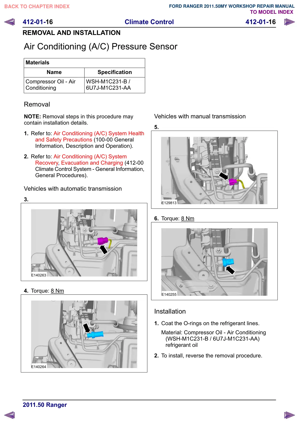
Vehicles with automatic transmission
3.
E140263
4. Torque: 8 Nm
E140264
Vehicles with manual transmission
5.
E129813
6. Torque: 8 Nm
E140255
Installation
1. Coat the O-rings on the refrigerant lines.
Material: Compressor Oil - Air Conditioning
(WSH-M1C231-B / 6U7J-M1C231-AA)
refrigerant oil
2. To install, reverse the removal procedure.
412-01-17
Climate Control
412-01-17
REMOVAL AND INSTALLATION
Condenser – 2.5L Duratec-HE (122kW/165PS) - MI4
Materials
Name
Specification
Compressor Oil - Air
WSH-M1C231-B /
Conditioning
6U7J-M1C231-AA
Removal
NOTE: Removal steps in this procedure may
contain installation details.
1. Refer to: Air Conditioning (A/C) System Health
and Safety Precautions (100-00 General
Information, Description and Operation).
2. Refer to: Air Conditioning (A/C) System
Recovery, Evacuation and Charging (412-00
Climate Control System - General Information,
General Procedures).
3. Refer to: Radiator Grille (501-08 Exterior Trim
and Ornamentation, Removal and Installation).
4. Refer to: Lifting (100-02 Jacking and Lifting,
Description and Operation).
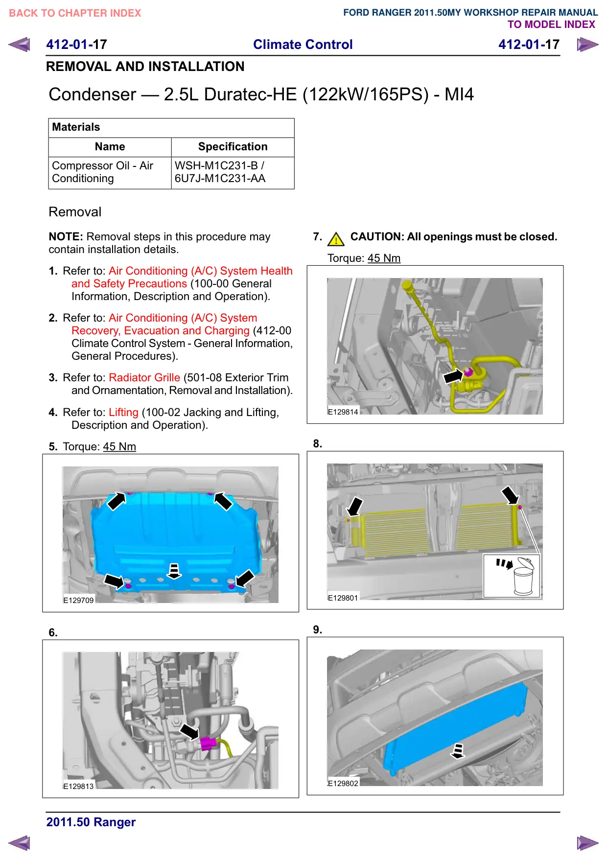
5. Torque: 45 Nm
E129709
6.
E129813
7.
CAUTION: All openings must be closed.
Torque: 45 Nm
E129814
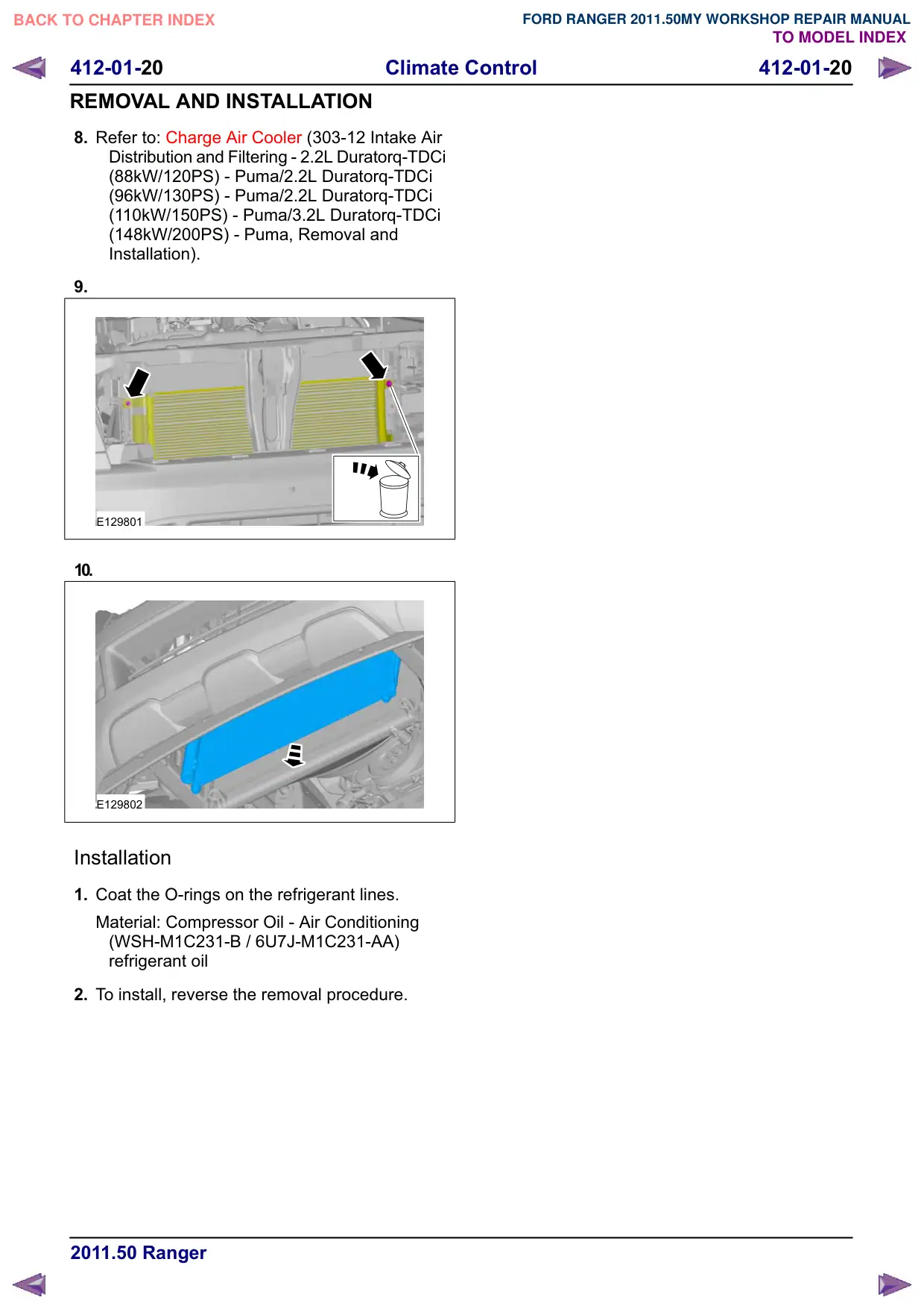
8.
E129801
9.
E129802
412-01-18
Climate Control
412-01-18
REMOVAL AND INSTALLATION
Installation
1. Coat the O-rings on the refrigerant lines.
Material: Compressor Oil - Air Conditioning
(WSH-M1C231-B / 6U7J-M1C231-AA)
refrigerant oil
2. To install, reverse the removal procedure.
412-01-19
Climate Control
412-01-19
REMOVAL AND INSTALLATION
Condenser – 2.2L Duratorq-TDCi (88kW/120PS) - Puma/2.2L
Duratorq-TDCi (96kW/130PS) - Puma/2.2L Duratorq-TDCi
(110kW/150PS) - Puma/3.2L Duratorq-TDCi (148kW/200PS)
- Puma
Materials
Name
Specification
Compressor Oil - Air
WSH-M1C231-B /
Conditioning
6U7J-M1C231-AA
Removal
NOTE: Removal steps in this procedure may
contain installation details.
1. Refer to: Air Conditioning (A/C) System Health
and Safety Precautions (100-00 General
Information, Description and Operation).
2. Refer to: Air Conditioning (A/C) System
Recovery, Evacuation and Charging (412-00
Climate Control System - General Information,
General Procedures).
3. Refer to: Radiator Grille (501-08 Exterior Trim
and Ornamentation, Removal and Installation).
4. Refer to: Lifting (100-02 Jacking and Lifting,
Description and Operation).
5. Torque: 15 Nm
E129709
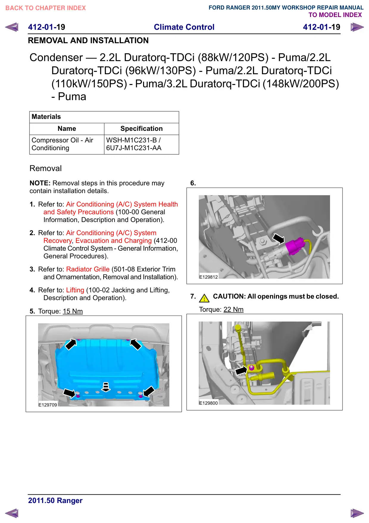
6.
E129812
7.
CAUTION: All openings must be closed.
Torque: 22 Nm
E129800
412-01-21
Climate Control
412-01-21
REMOVAL AND INSTALLATION
Receiver Drier
Removal
NOTE: Removal steps in this procedure may
contain installation details.
1. Refer to: Air Conditioning (A/C) System
Recovery, Evacuation and Charging (412-00
Climate Control System - General Information,
General Procedures).
2. Refer to: Lifting (100-02 Jacking and Lifting,
Description and Operation).
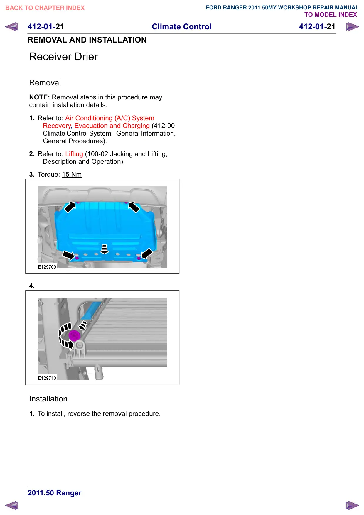
3. Torque: 15 Nm
E129709
4.
E129710
Installation
1. To install, reverse the removal procedure.
412-01-22
Climate Control
412-01-22
REMOVAL AND INSTALLATION
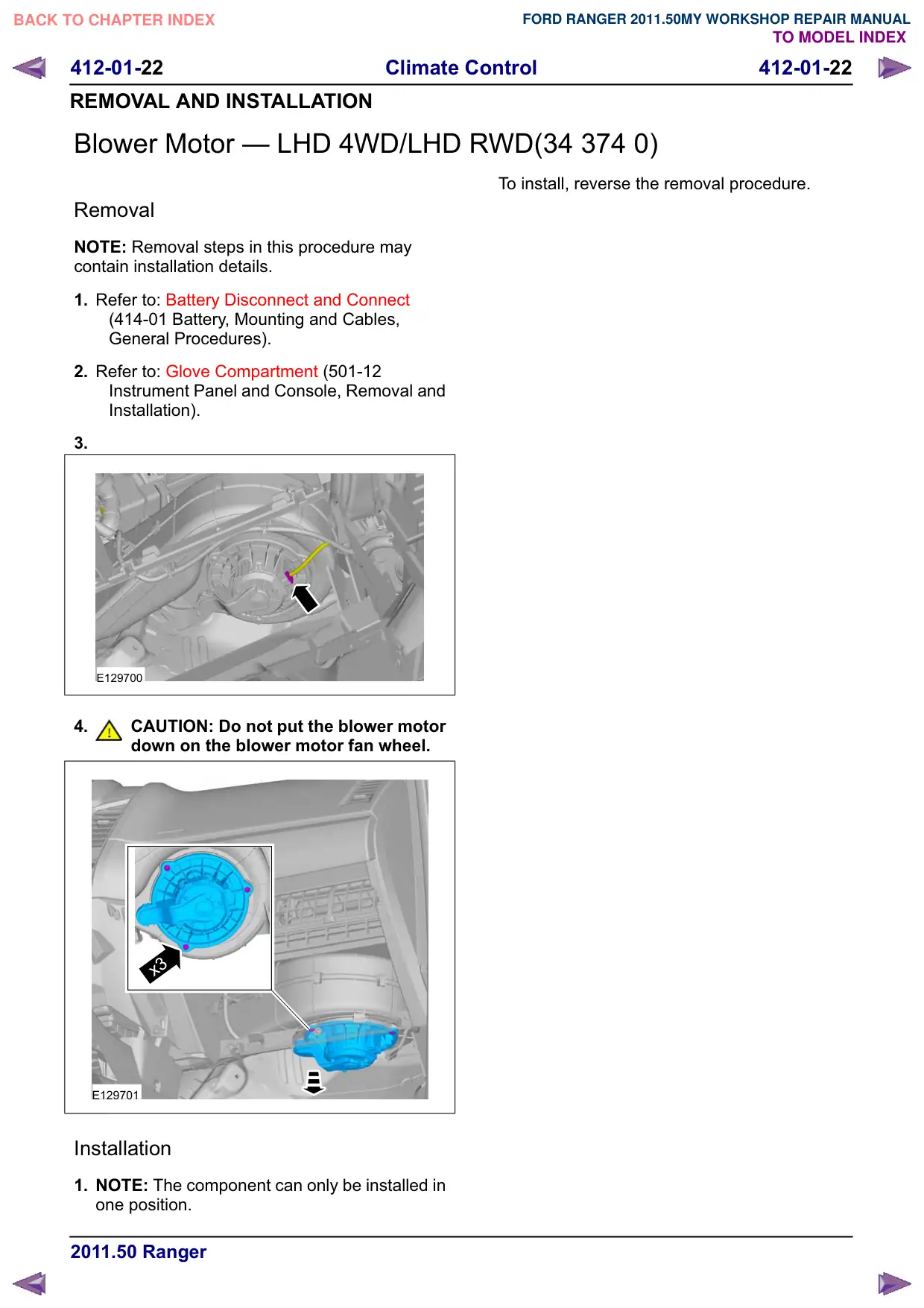
Blower Motor – LHD 4WD/LHD RWD(34 374 0)
Removal
NOTE: Removal steps in this procedure may
contain installation details.
1. Refer to: Battery Disconnect and Connect
(414-01 Battery, Mounting and Cables,
General Procedures).
2. Refer to: Glove Compartment (501-12
Instrument Panel and Console, Removal and
Installation).
3.
E129700
4.
CAUTION: Do not put the blower motor
down on the blower motor fan wheel.
x3
E129701
Installation
1. NOTE: The component can only be installed in
one position.
To install, reverse the removal procedure.
412-01-23
Climate Control
412-01-23
REMOVAL AND INSTALLATION
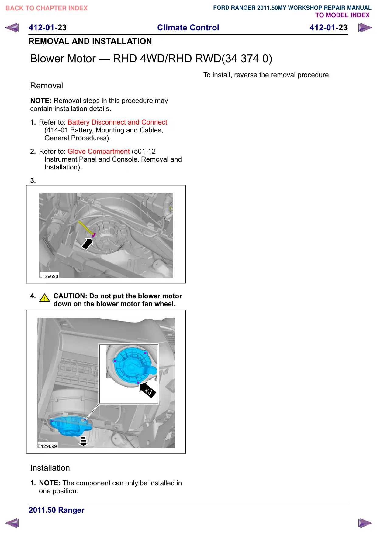
Blower Motor – RHD 4WD/RHD RWD(34 374 0)
Removal
NOTE: Removal steps in this procedure may
contain installation details.
1. Refer to: Battery Disconnect and Connect
(414-01 Battery, Mounting and Cables,
General Procedures).
2. Refer to: Glove Compartment (501-12
Instrument Panel and Console, Removal and
Installation).
3.
E129698
4.
CAUTION: Do not put the blower motor
down on the blower motor fan wheel.
x3
E129699
Installation
1. NOTE: The component can only be installed in
one position.
To install, reverse the removal procedure.
412-01-24
Climate Control
412-01-24
REMOVAL AND INSTALLATION
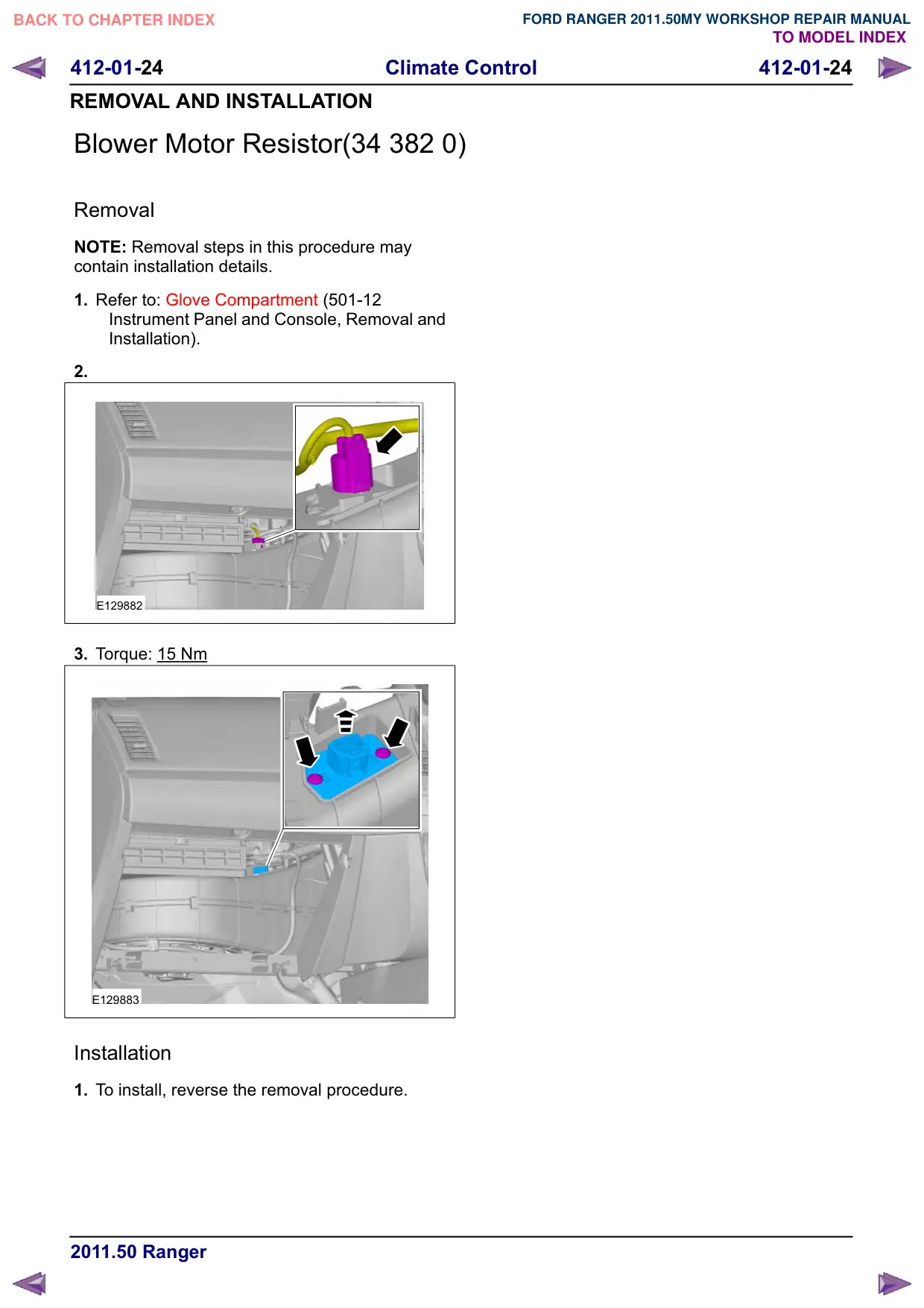
Blower Motor Resistor(34 382 0)
Removal
NOTE: Removal steps in this procedure may
contain installation details.
1. Refer to: Glove Compartment (501-12
Instrument Panel and Console, Removal and
Installation).
2.
E129882
3. Torque: 15 Nm
E129883
Installation
1. To install, reverse the removal procedure.
412-01-25
Climate Control
412-01-25
REMOVAL AND INSTALLATION
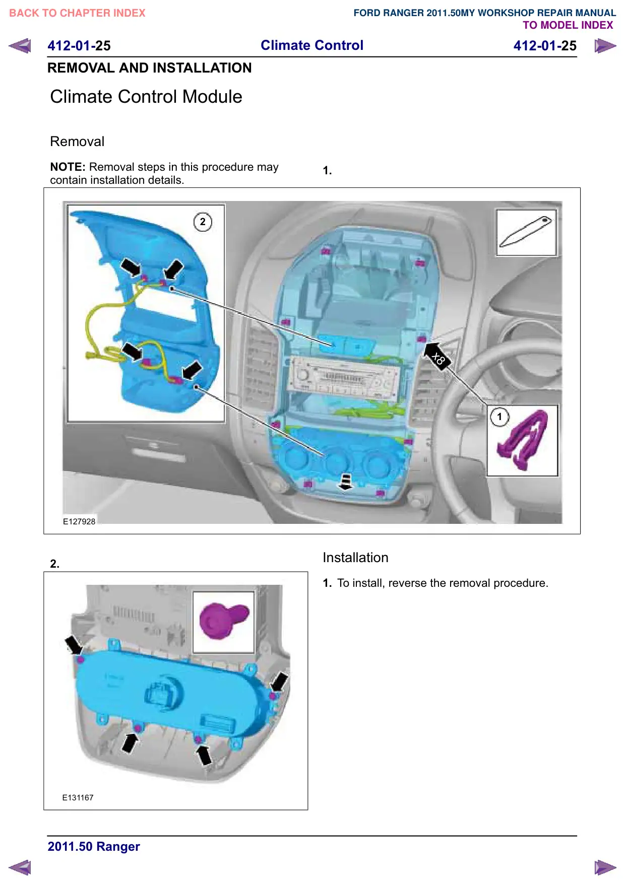
Climate Control Module
Removal
NOTE: Removal steps in this procedure may
contain installation details.
2
E127928
2.
E131167
1.
x8
1
Installation
1. To install, reverse the removal procedure.
412-01-26
Climate Control
412-01-26
REMOVAL AND INSTALLATION
Pollen Filter
Removal
NOTE: Removal steps in this procedure may
contain installation details.
1. Refer to: Glove Compartment (501-12
Instrument Panel and Console, Removal and
Installation).
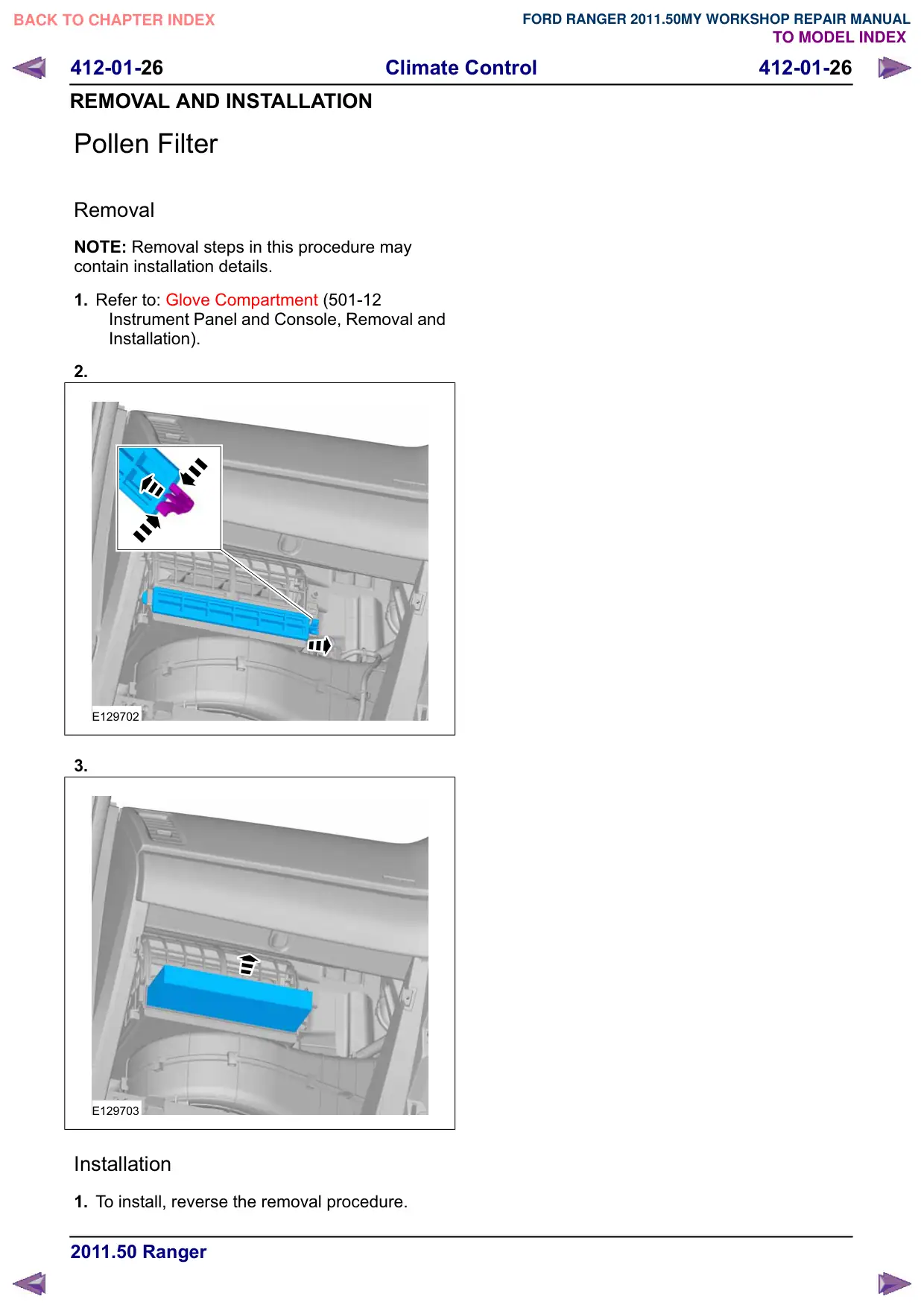
2.
E129702
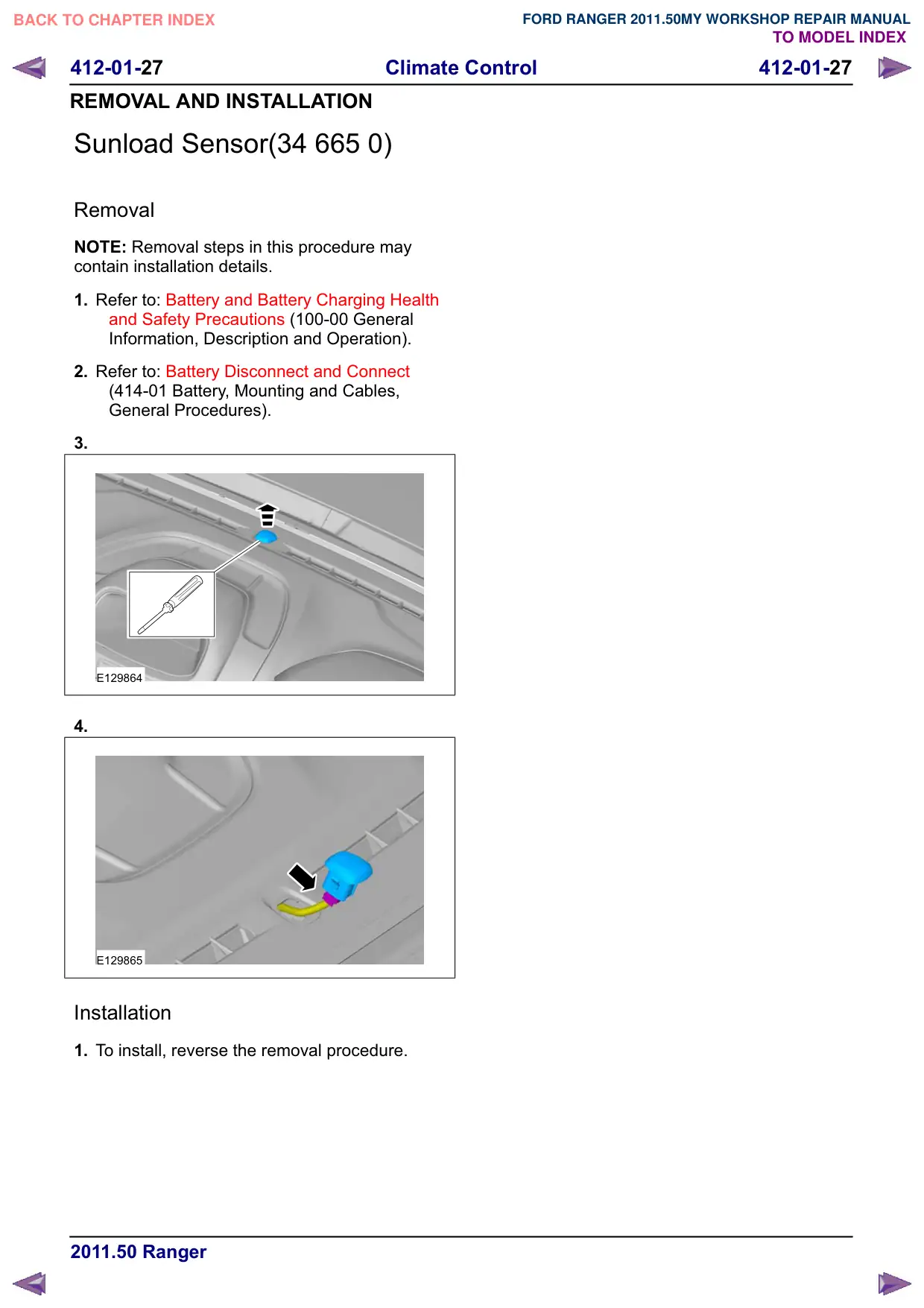
3.
E129703
Installation
1. To install, reverse the removal procedure.
412-01-27
Climate Control
412-01-27
REMOVAL AND INSTALLATION
Sunload Sensor(34 665 0)
Removal
NOTE: Removal steps in this procedure may
contain installation details.
1. Refer to: Battery and Battery Charging Health
and Safety Precautions (100-00 General
Information, Description and Operation).
2. Refer to: Battery Disconnect and Connect
(414-01 Battery, Mounting and Cables,
General Procedures).
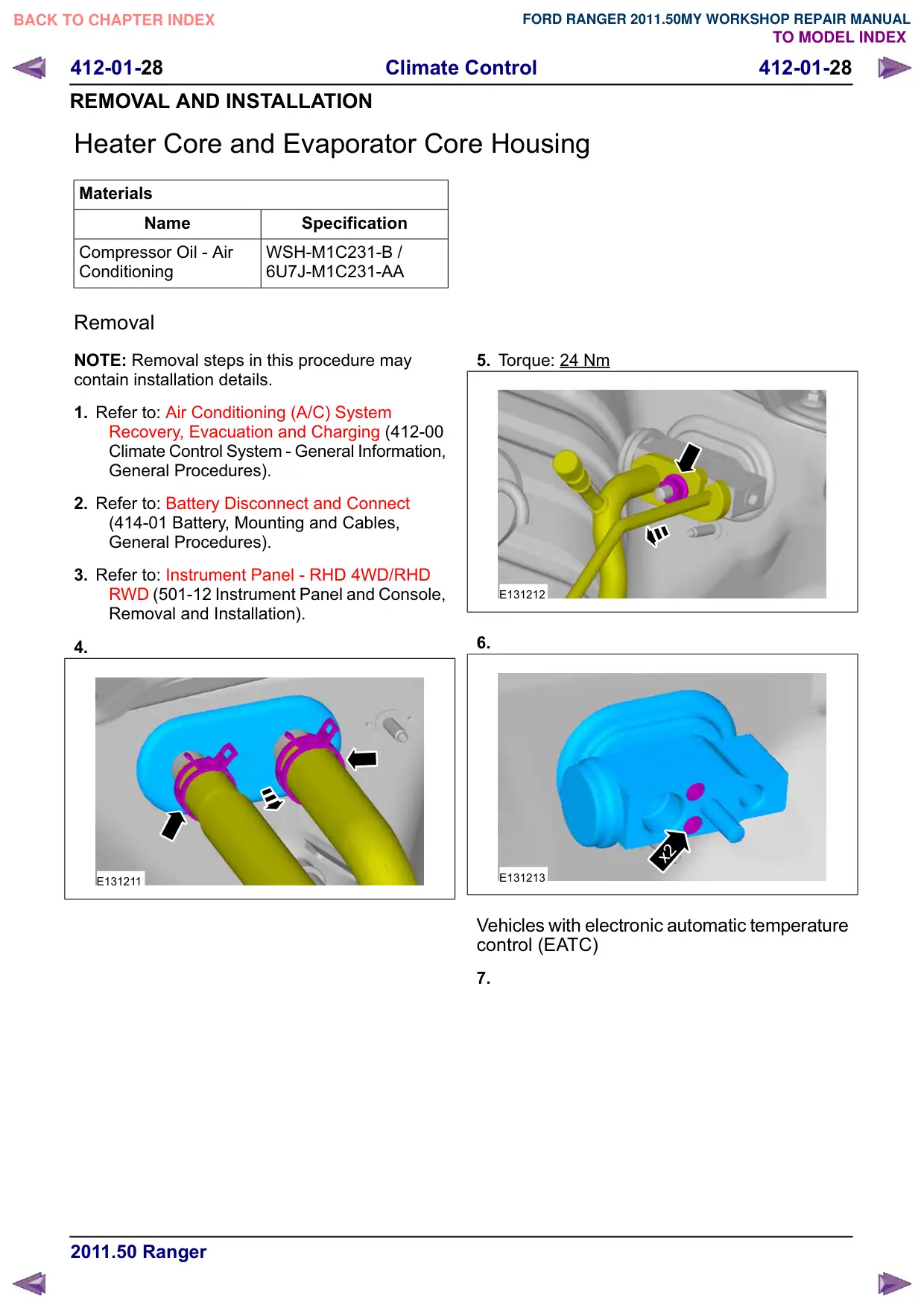
3.
E129864
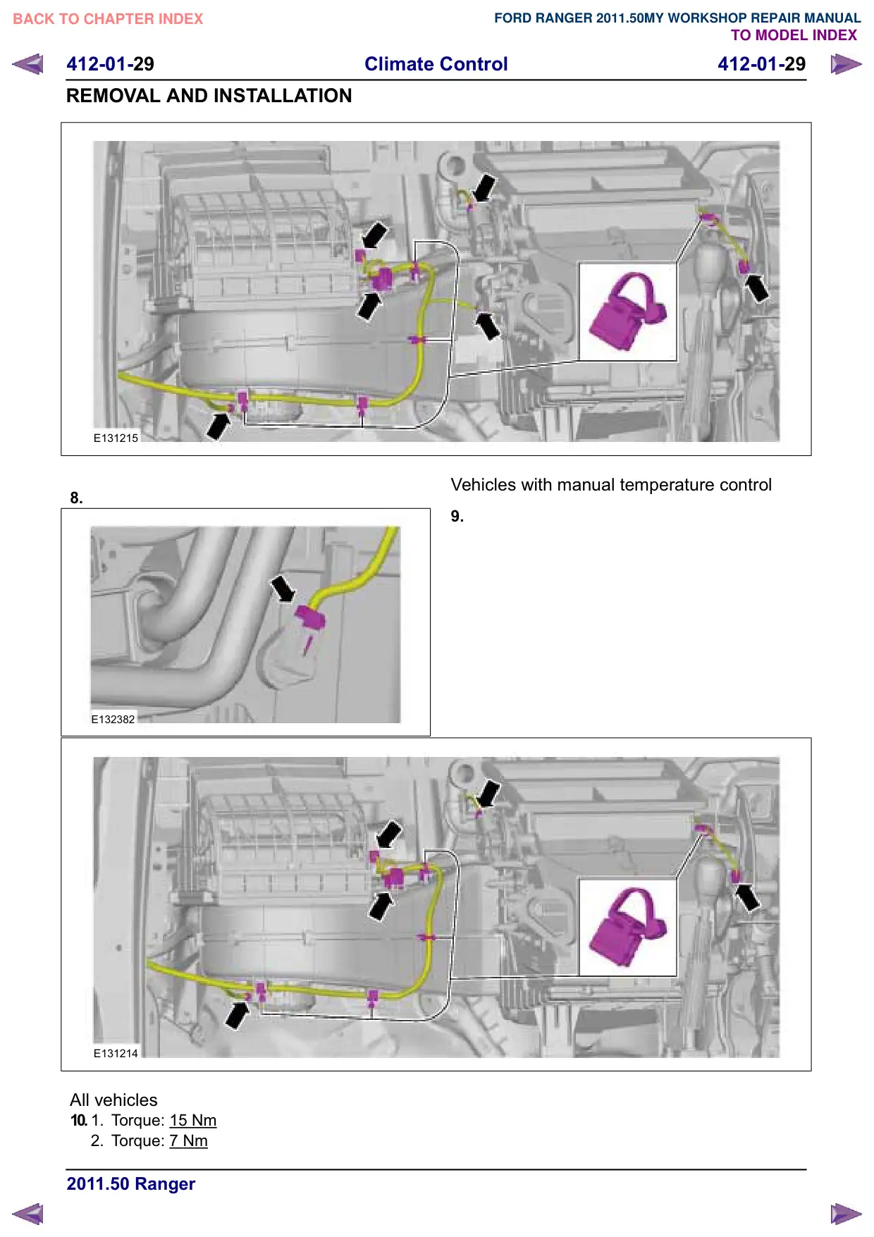
4.
E129865
Installation
1. To install, reverse the removal procedure.
412-01-28
Climate Control
412-01-28
REMOVAL AND INSTALLATION
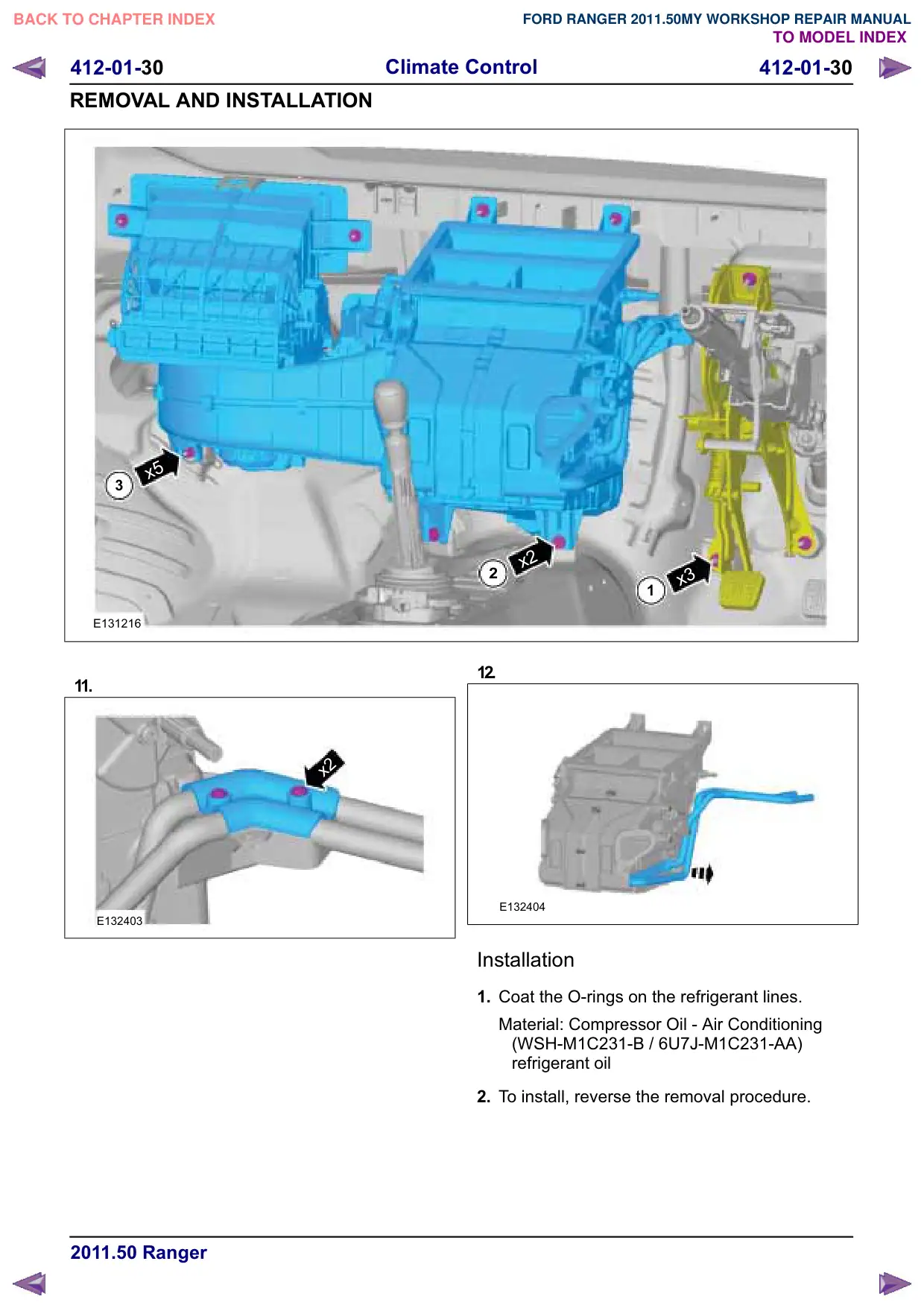
Heater Core and Evaporator Core Housing
Materials
Name
Specification
Compressor Oil - Air
WSH-M1C231-B /
Conditioning
6U7J-M1C231-AA
Removal
NOTE: Removal steps in this procedure may
contain installation details.
1. Refer to: Air Conditioning (A/C) System
Recovery, Evacuation and Charging (412-00
Climate Control System - General Information,
General Procedures).
2. Refer to: Battery Disconnect and Connect
(414-01 Battery, Mounting and Cables,
General Procedures).
3. Refer to: Instrument Panel - RHD 4WD/RHD
5:' (501-12 Instrument Panel and Console,
Removal and Installation).
4.
E131211
5. Torque: 24 Nm
E131212
6.
x2
E131213
Vehicles with electronic automatic temperature
control (EATC)
7.
412-01-29
Climate Control
412-01-29
REMOVAL AND INSTALLATION
E131215
8.
E132382
E131214
All vehicles
10.
1.
Torque: 15
Nm
2. Torque: 7 Nm
Vehicles with manual temperature control
9.
412-01-31
Climate Control
412-01-31
REMOVAL AND INSTALLATION
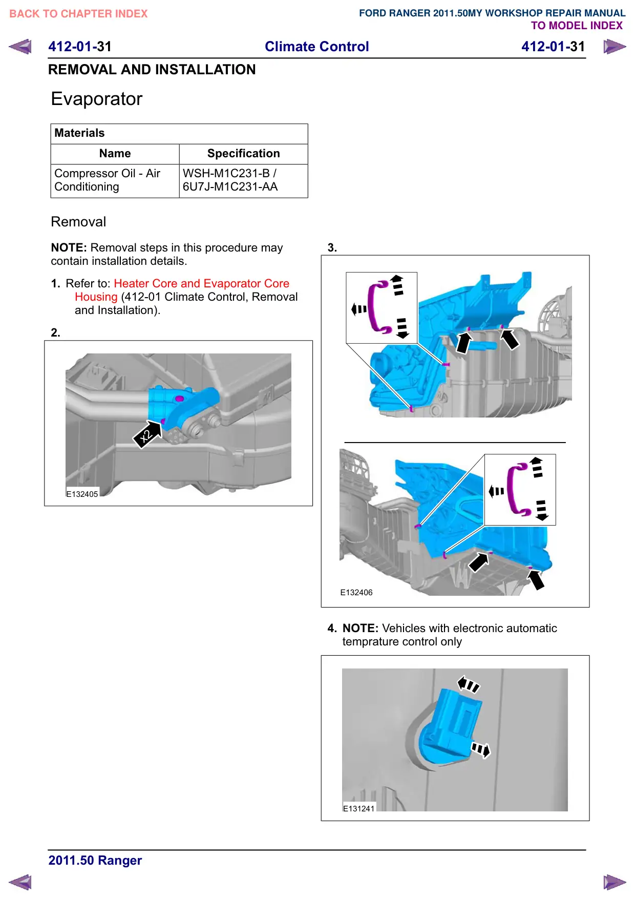
Evaporator
Materials
Name
Specification
Compressor Oil - Air
WSH-M1C231-B /
Conditioning
6U7J-M1C231-AA
Removal
NOTE: Removal steps in this procedure may
contain installation details.
1. Refer to: Heater Core and Evaporator Core
Housing (412-01 Climate Control, Removal
and Installation).
2.
x2
E132405
3.
E132406
4. NOTE: Vehicles with electronic automatic
temprature control only
E131241
412-01-32
Climate Control
412-01-32
REMOVAL AND INSTALLATION
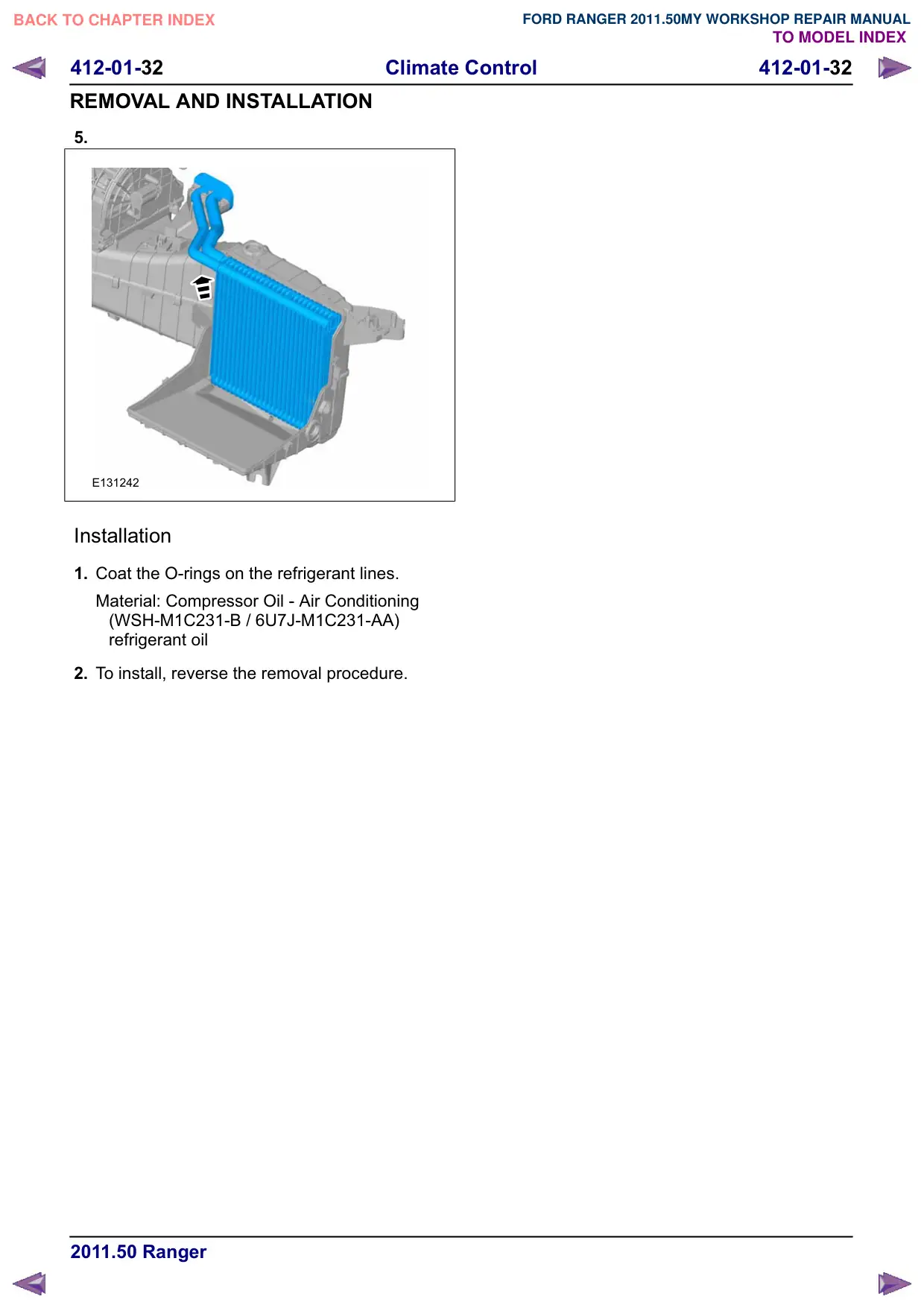
5.
E131242
Installation
1. Coat the O-rings on the refrigerant lines.
Material: Compressor Oil - Air Conditioning
(WSH-M1C231-B / 6U7J-M1C231-AA)
refrigerant oil
2. To install, reverse the removal procedure.
412-01-33
Climate Control
412-01-33
REMOVAL AND INSTALLATION
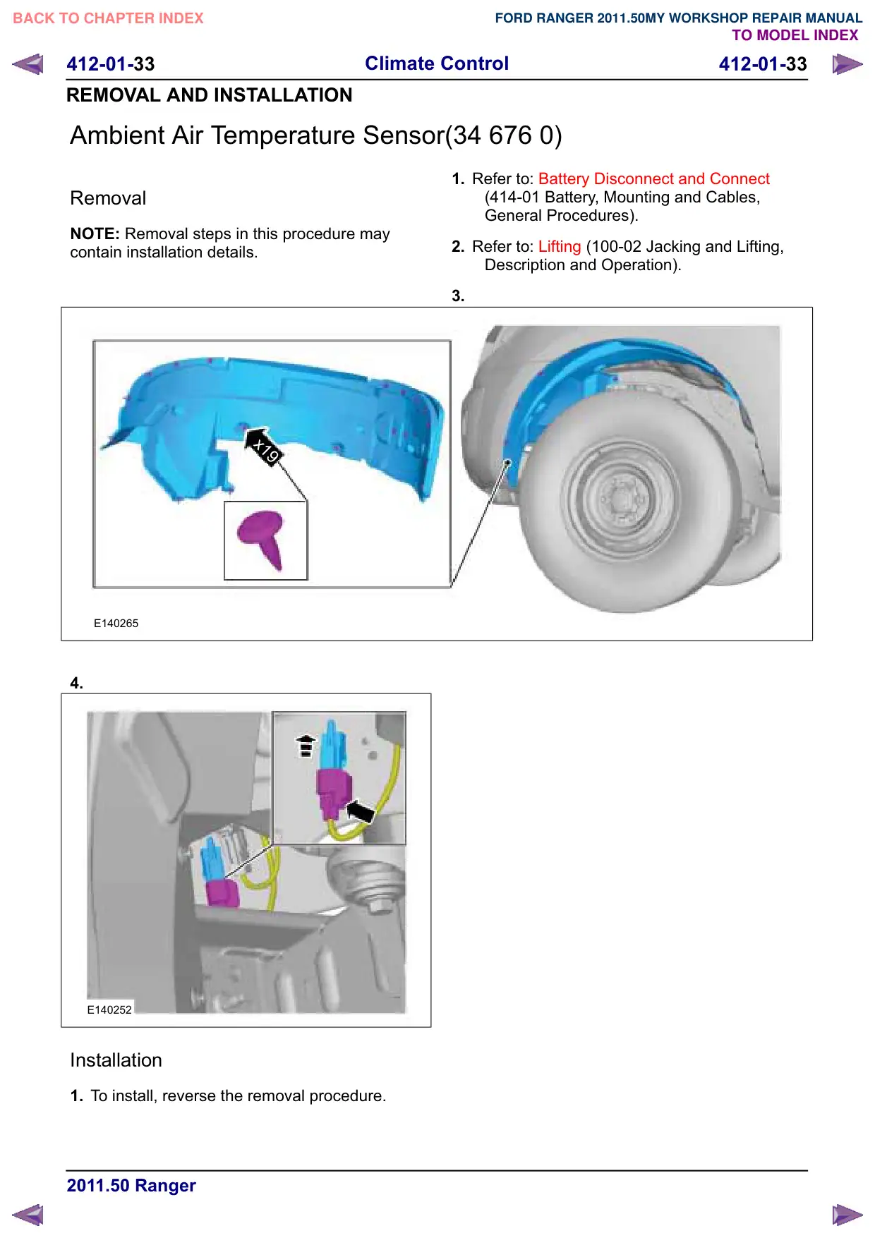
Ambient Air Temperature Sensor(34 676 0)
Removal
NOTE: Removal steps in this procedure may
contain installation details.
x19
E140265
4.
E140252
Installation
1. To install, reverse the removal procedure.
1. Refer to: Battery Disconnect and Connect
(414-01 Battery, Mounting and Cables,
General Procedures).
2. Refer to: Lifting (100-02 Jacking and Lifting,
Description and Operation).
3.