206-06-3
Hydraulic Brake Actuation
206-06-3
REMOVAL AND INSTALLATION
Brake Master Cylinder – LHD 4WD/LHD RWD(12 343 0)
Removal
NOTE: Removal steps in this procedure may
contain installation details.
1. Refer to: Health and Safety Precautions (100-00
General Information, Description and
Operation).
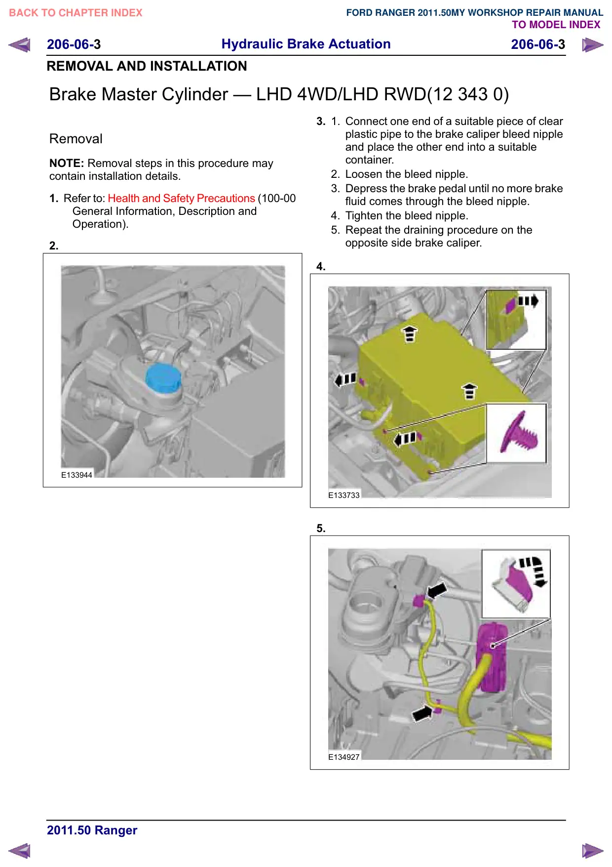
2.
E133944
3.
1.
Connect one end of a suitable piece of clear
plastic pipe to the brake caliper bleed nipple
and place the other end into a suitable
container.
2. Loosen the bleed nipple.
3. Depress the brake pedal until no more brake
fluid comes through the bleed nipple.
4. Tighten the bleed nipple.
5. Repeat the draining procedure on the
opposite side brake caliper.
4.
E133733
5.
E134927
Hydraulic Brake Actuation
206-06-4
206-06-4
REMOVAL AND INSTALLATION
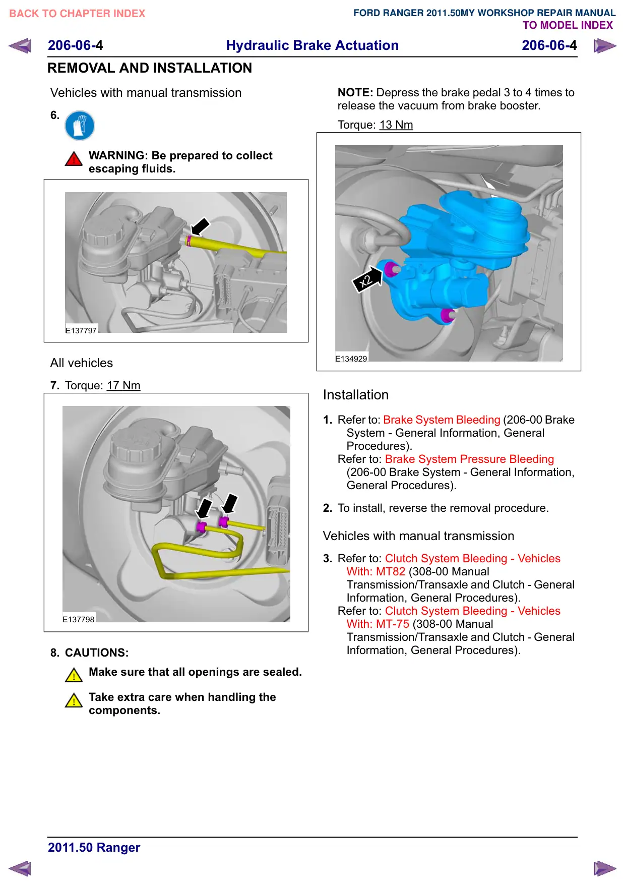
Vehicles with manual transmission
6.
WARNING: Be prepared to collect
escaping fluids.
E137797
All vehicles
7. Torque: 17 Nm
E137798
8. CAUTIONS:
Make sure that all openings are sealed.
Take extra care when handling the
components.
NOTE: Depress the brake pedal 3 to 4 times to
release the vacuum from brake booster.
Torque: 13 Nm
x2
E134929
Installation
1. Refer to: Brake System Bleeding (206-00 Brake
System - General Information, General
Procedures).
Refer to: Brake System Pressure Bleeding
(206-00 Brake System - General Information,
General Procedures).
2. To install, reverse the removal procedure.
Vehicles with manual transmission
3. Refer to: Clutch System Bleeding - Vehicles
With: MT82 (308-00 Manual
Transmission/Transaxle and Clutch - General
Information, General Procedures).
Refer to: Clutch System Bleeding - Vehicles
With: MT-75 (308-00 Manual
Transmission/Transaxle and Clutch - General
Information, General Procedures).
Hydraulic Brake Actuation
206-06-5
206-06-5
REMOVAL AND INSTALLATION
Brake Master Cylinder – RHD 4WD/RHD RWD(12 343 0)
Removal
NOTE: Removal steps in this procedure may
contain installation details.
1. Refer to: Health and Safety Precautions (100-00
General Information, Description and
Operation).
2.
1.
Connect one end of a suitable piece of clear
plastic pipe to the brake caliper bleed nipple
and place the other end into a suitable
container.
2. Loosen the bleed nipple.
3. Depress the brake pedal until no more brake
fluid comes through the bleed nipple.
4. Tighten the bleed nipple.
5. Repeat the draining procedure on the
opposite side brake caliper.
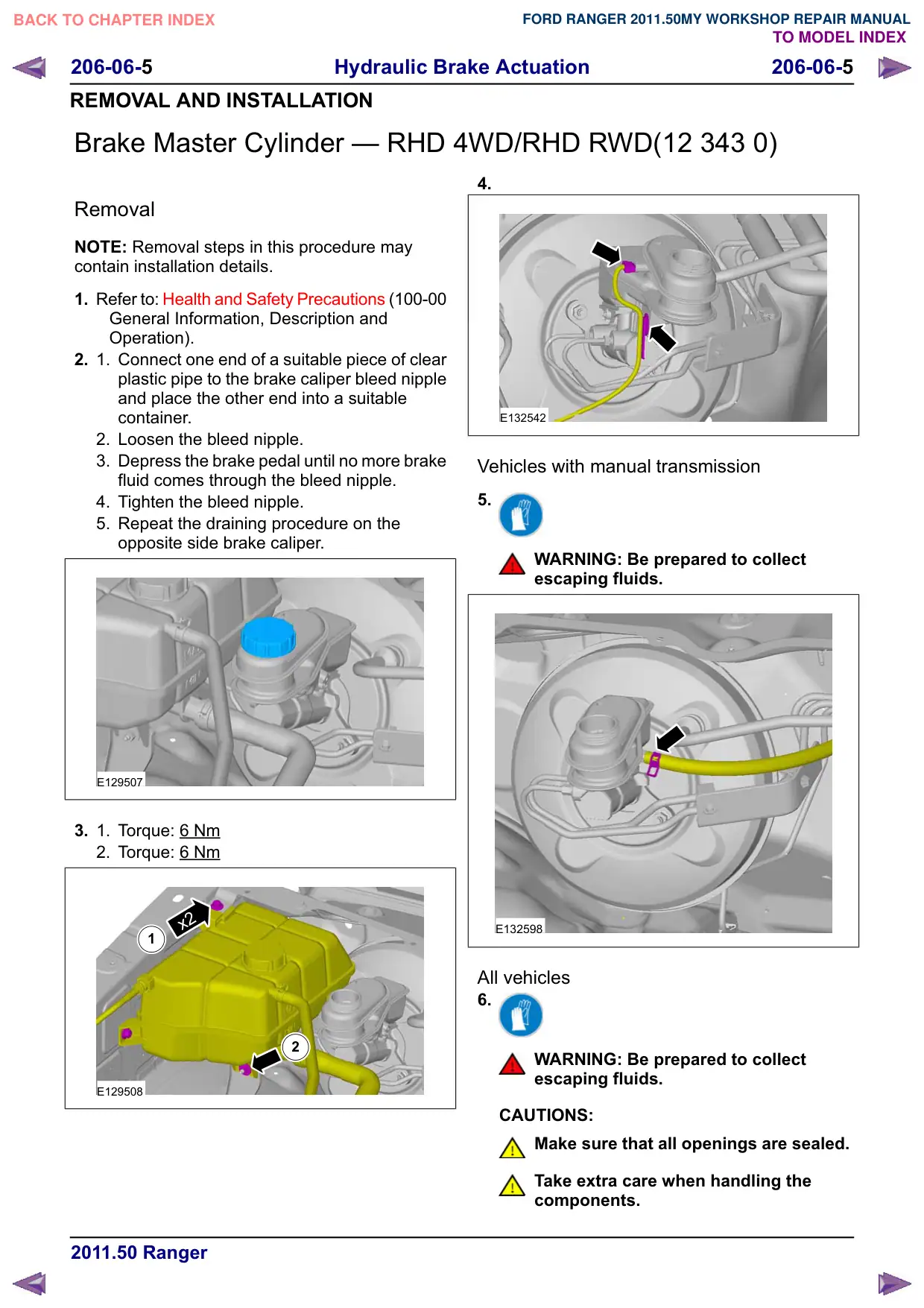
E129507
3.
1.
Torque: 6 Nm
2. Torque: 6 Nm
x2
1
2
E129508
4.
E132542
Vehicles with manual transmission
5.
WARNING: Be prepared to collect
escaping fluids.
E132598
All vehicles
6.
WARNING: Be prepared to collect
escaping fluids.
CAUTIONS:
Make sure that all openings are sealed.
Take extra care when handling the
components.
Hydraulic Brake Actuation
206-06-6
206-06-6
REMOVAL AND INSTALLATION
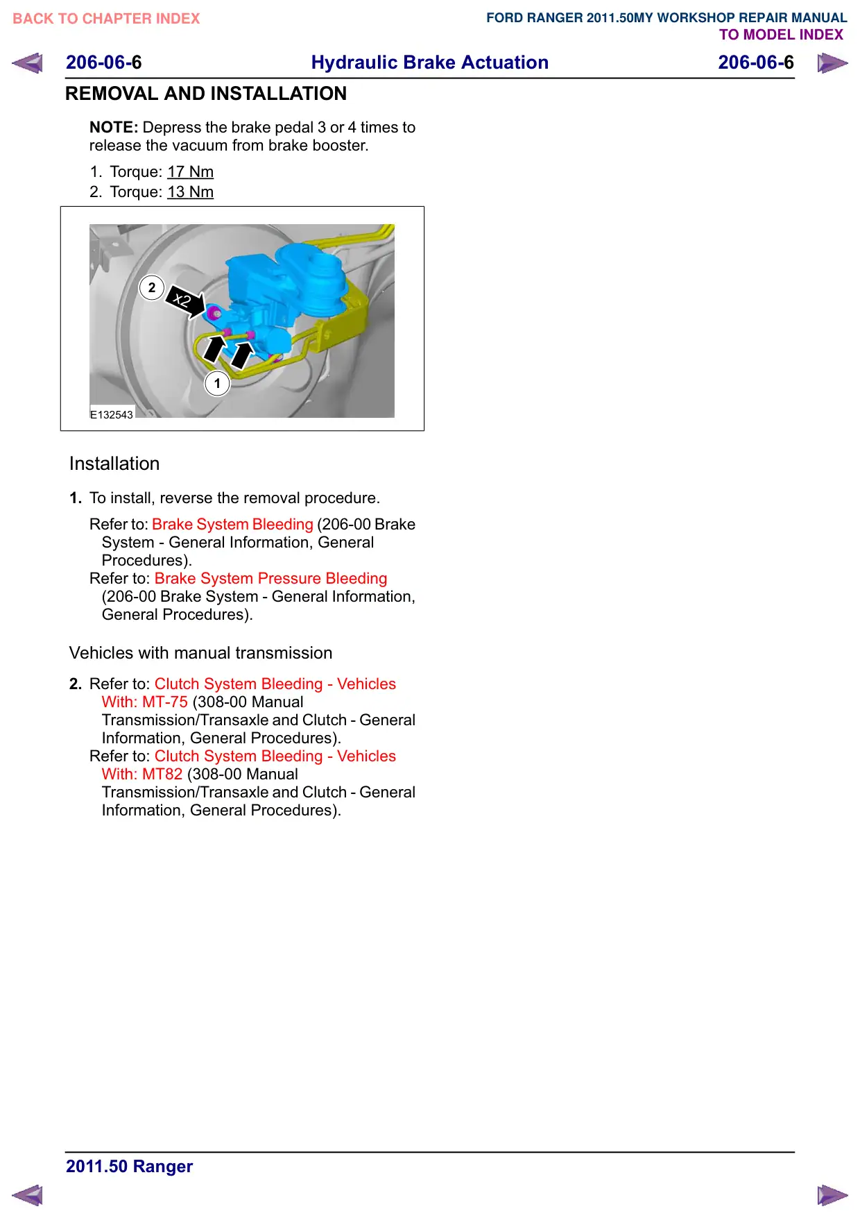
NOTE: Depress the brake pedal 3 or 4 times to
release the vacuum from brake booster.
1. Torque: 17 Nm
2. Torque: 13 Nm
2
x2
1
E132543
Installation
1. To install, reverse the removal procedure.
Refer to: Brake System Bleeding (206-00 Brake
System - General Information, General
Procedures).
Refer to: Brake System Pressure Bleeding
(206-00 Brake System - General Information,
General Procedures).
Vehicles with manual transmission
2. Refer to: Clutch System Bleeding - Vehicles
With: MT-75 (308-00 Manual
Transmission/Transaxle and Clutch - General
Information, General Procedures).
Refer to: Clutch System Bleeding - Vehicles
With: MT82 (308-00 Manual
Transmission/Transaxle and Clutch - General
Information, General Procedures).
Hydraulic Brake Actuation
206-06-7
206-06-7
REMOVAL AND INSTALLATION
Brake Pedal and Bracket
Removal
NOTE: Removal steps in this procedure may
contain installation details.
1. Refer to: Brake Booster - RHD 4WD/RHD RWD
(206-07 Power Brake Actuation, Removal and
Installation).
Refer to: Brake Booster - LHD 4WD/LHD RWD
(206-07 Power Brake Actuation, Removal and
Installation).
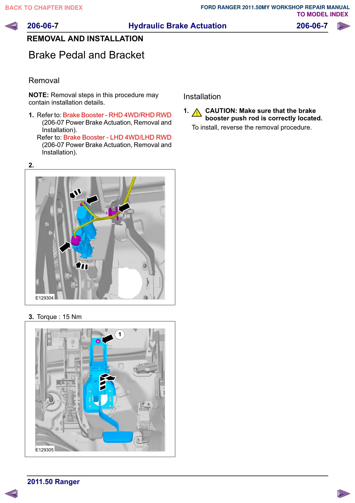
2.
E129304
3. Torque : 15 Nm
1
E129305
Installation
1.
CAUTION: Make sure that the brake
booster push rod is correctly located.
To install, reverse the removal procedure.