Controles eletrônicos do motor – Funcionamento do sistema e componentes
Electronic Engine Controls œ System Operation and Component
Texto da página
Link desta página: https://ranger.mbrace.com.br/oficina/863
Imagem: https://ranger.mbrace.com.br/img/oficina/863.webp
Electronic Engine Controls – 2.5L Duratec-HE (122kW/165PS)
303-14A-6
303-14A-6
- MI4
DESCRIPTION AND OPERATION
primary circuit, thereby producing an ignition spark
which passes to the cylinder via the spark plug.
The spark plugs are activated in pairs (cylinders 1
and 4, and cylinders 2 and 3) and send a strong
main spark to the cylinder in the compression cycle
and a weak secondary spark to the cylinder in the
exhaust cycle. The main spark is generated
automatically in the cylinder that is in the
compression cycle, because a higher resistance
exists between the electrodes on account of the
high compression.
On one spark plug a spark jumps across from the
center electrode to the earth electrode and on the
other spark plug from the earth electrode to the
center electrode.
Crankshaft Position (CKP) Sensor
E135521
The CKP sensor is an inductive sensor that allows
the ECM to determine the angular position of the
crankshaft and the engine speed.
The CKP sensor is installed in the rear left side of
the sump body, in line with the engine drive plate.
The sensor is secured with a single screw and
sealed with an O-ring. A two pin electrical
connector provides the interface with the engine
harness.
The head of the CKP sensor faces a reluctor ring
pressed into the outer circumference of the engine
drive plate. The reluctor ring has a 60 minus 2 tooth
pattern. There are 58 teeth at 6° intervals, with two
teeth removed to provide a reference point with a
centerline that is 21° BTDC (before top dead
center) on cylinder 1 of bank A.
If the CKP sensor fails, the ECM:
Uses signals from the CMP sensors to determine
the angular position of the crankshaft and the
engine speed
Adopts a limp home mode where engine speed is
limited to a maximum of 3000 rev/min. With a failed
CKP sensor, engine starts will require a long crank
time while the ECM determines the angular position
of the crankshaft.
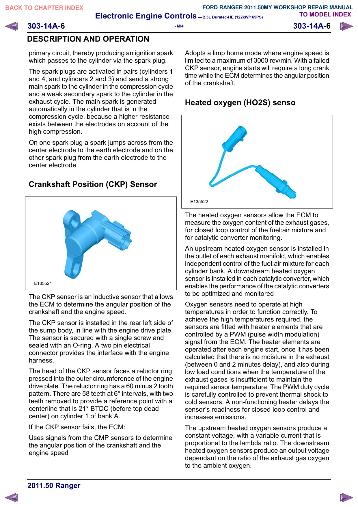
Heated oxygen (HO2S) senso
E135522
The heated oxygen sensors allow the ECM to
measure the oxygen content of the exhaust gases,
for closed loop control of the fuel:air mixture and
for catalytic converter monitoring.
An upstream heated oxygen sensor is installed in
the outlet of each exhaust manifold, which enables
independent control of the fuel:air mixture for each
cylinder bank. A downstream heated oxygen
sensor is installed in each catalytic converter, which
enables the performance of the catalytic converters
to be optimized and monitored
Oxygen sensors need to operate at high
temperatures in order to function correctly. To
achieve the high temperatures required, the
sensors are fitted with heater elements that are
controlled by a PWM (pulse width modulation)
signal from the ECM. The heater elements are
operated after each engine start, once it has been
calculated that there is no moisture in the exhaust
(between 0 and 2 minutes delay), and also during
low load conditions when the temperature of the
exhaust gases is insufficient to maintain the
required sensor temperature. The PWM duty cycle
is carefully controlled to prevent thermal shock to
cold sensors. A non-functioning heater delays the
sensor‘s readiness for closed loop control and
increases emissions.
The upstream heated oxygen sensors produce a
constant voltage, with a variable current that is
proportional to the lambda ratio. The downstream
heated oxygen sensors produce an output voltage
dependant on the ratio of the exhaust gas oxygen
to the ambient oxygen.