Electronic Engine Controls – 2.5L Duratec-HE (122kW/165PS)
303-14A-5
303-14A-5
- MI4
DESCRIPTION AND OPERATION
5
4
3
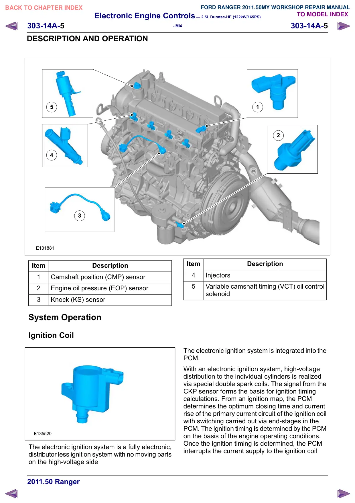
E131881
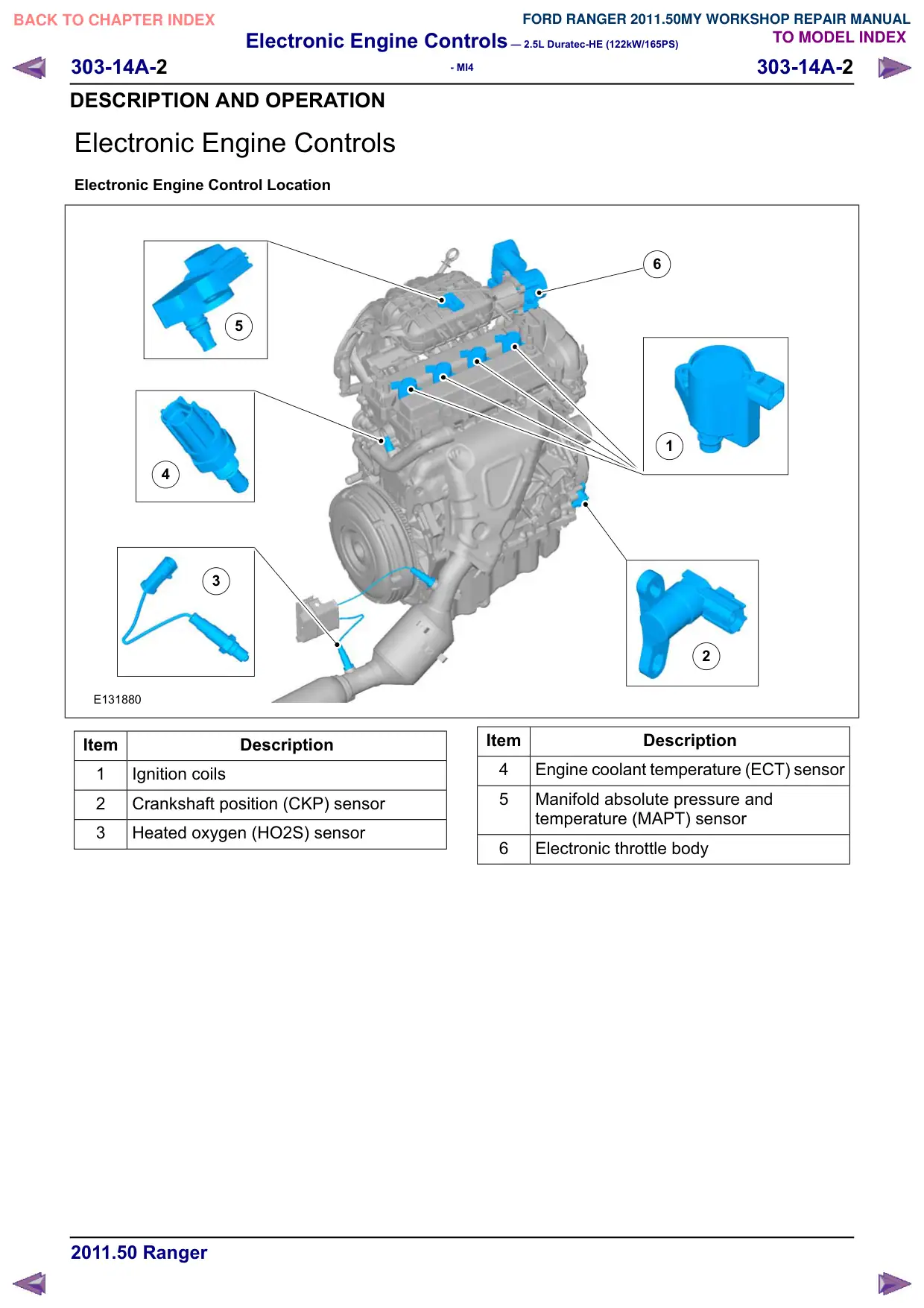
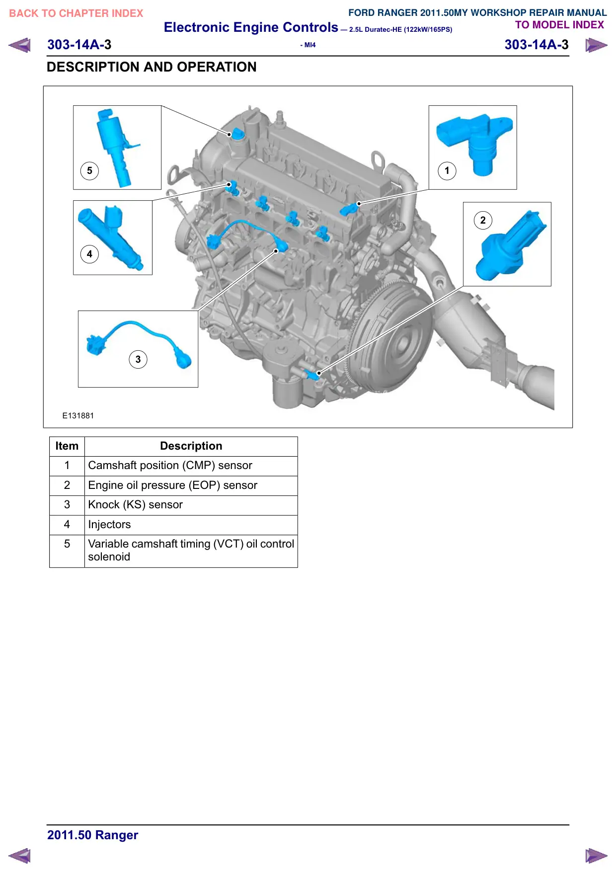
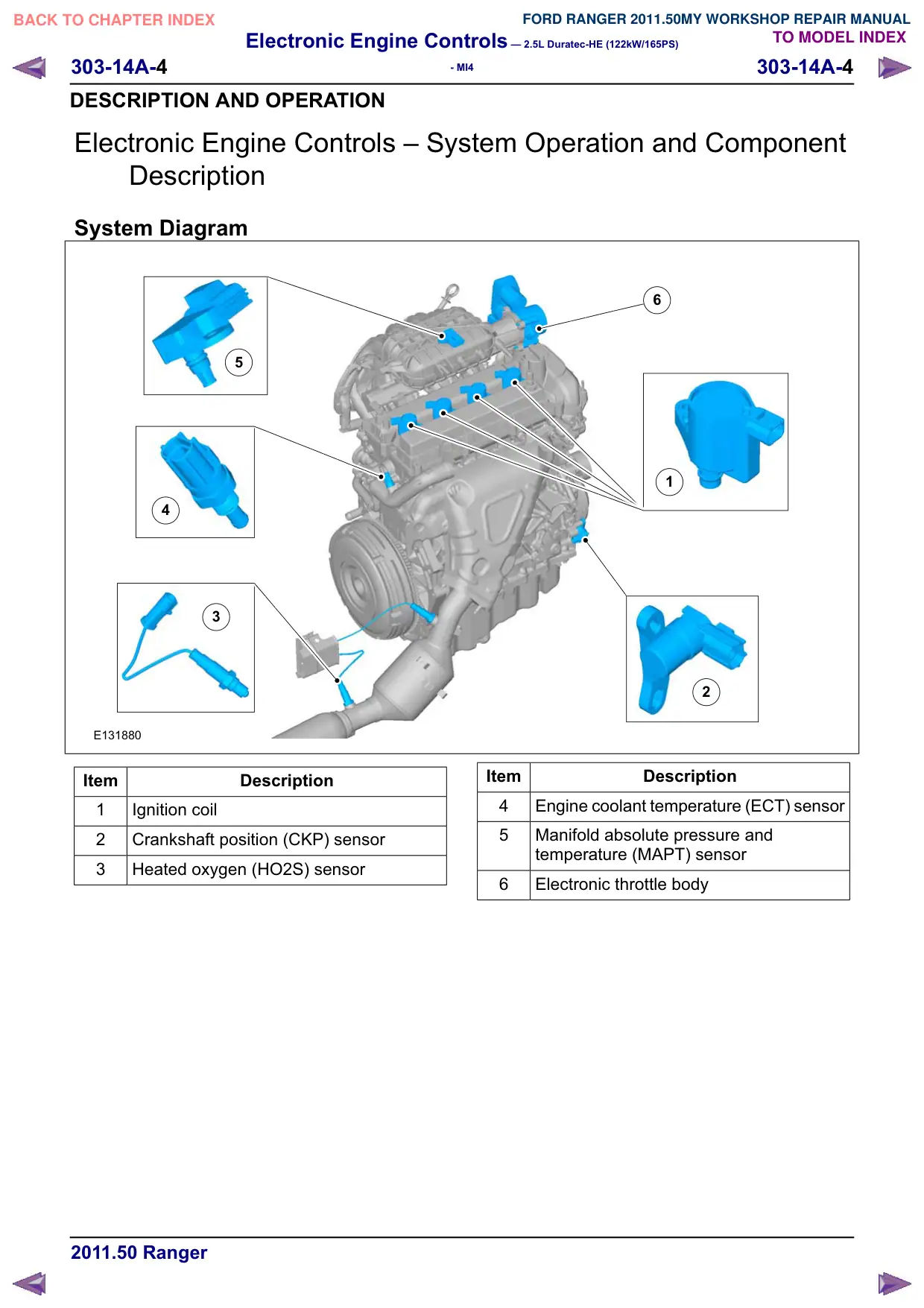
Item
Description
1
Camshaft position (CMP) sensor
2
Engine oil pressure (EOP) sensor
3
Knock (KS) sensor
System Operation
Ignition Coil
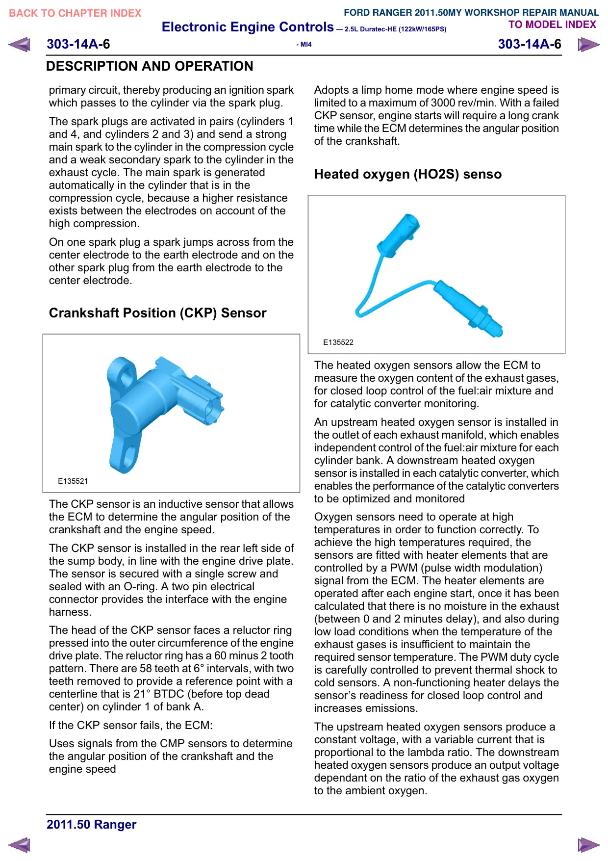
E135520
The electronic ignition system is a fully electronic,
distributor less ignition system with no moving parts
on the high-voltage side
1
2
Item
Description
4
Injectors
5
Variable camshaft timing (VCT) oil control
solenoid
The electronic ignition system is integrated into the
PCM.
With an electronic ignition system, high-voltage
distribution to the individual cylinders is realized
via special double spark coils. The signal from the
CKP sensor forms the basis for ignition timing
calculations. From an ignition map, the PCM
determines the optimum closing time and current
rise of the primary current circuit of the ignition coil
with switching carried out via end-stages in the
PCM. The ignition timing is determined by the PCM
on the basis of the engine operating conditions.
Once the ignition timing is determined, the PCM
interrupts the current supply to the ignition coil
Electronic Engine Controls – 2.5L Duratec-HE (122kW/165PS)
303-14A-6
303-14A-6
- MI4
DESCRIPTION AND OPERATION
primary circuit, thereby producing an ignition spark
which passes to the cylinder via the spark plug.
The spark plugs are activated in pairs (cylinders 1
and 4, and cylinders 2 and 3) and send a strong
main spark to the cylinder in the compression cycle
and a weak secondary spark to the cylinder in the
exhaust cycle. The main spark is generated
automatically in the cylinder that is in the
compression cycle, because a higher resistance
exists between the electrodes on account of the
high compression.
On one spark plug a spark jumps across from the
center electrode to the earth electrode and on the
other spark plug from the earth electrode to the
center electrode.
Crankshaft Position (CKP) Sensor
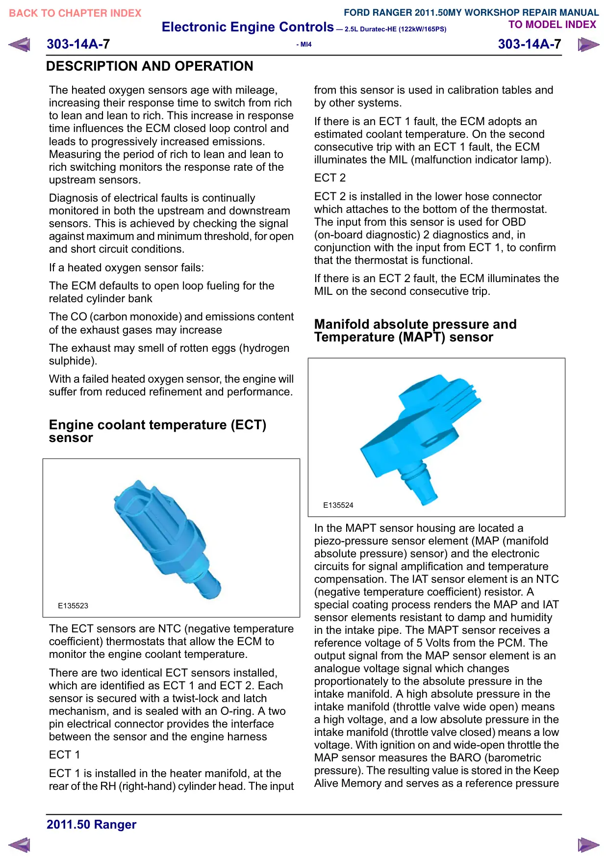
E135521
The CKP sensor is an inductive sensor that allows
the ECM to determine the angular position of the
crankshaft and the engine speed.
The CKP sensor is installed in the rear left side of
the sump body, in line with the engine drive plate.
The sensor is secured with a single screw and
sealed with an O-ring. A two pin electrical
connector provides the interface with the engine
harness.
The head of the CKP sensor faces a reluctor ring
pressed into the outer circumference of the engine
drive plate. The reluctor ring has a 60 minus 2 tooth
pattern. There are 58 teeth at 6° intervals, with two
teeth removed to provide a reference point with a
centerline that is 21° BTDC (before top dead
center) on cylinder 1 of bank A.
If the CKP sensor fails, the ECM:
Uses signals from the CMP sensors to determine
the angular position of the crankshaft and the
engine speed
Adopts a limp home mode where engine speed is
limited to a maximum of 3000 rev/min. With a failed
CKP sensor, engine starts will require a long crank
time while the ECM determines the angular position
of the crankshaft.
Heated oxygen (HO2S) senso
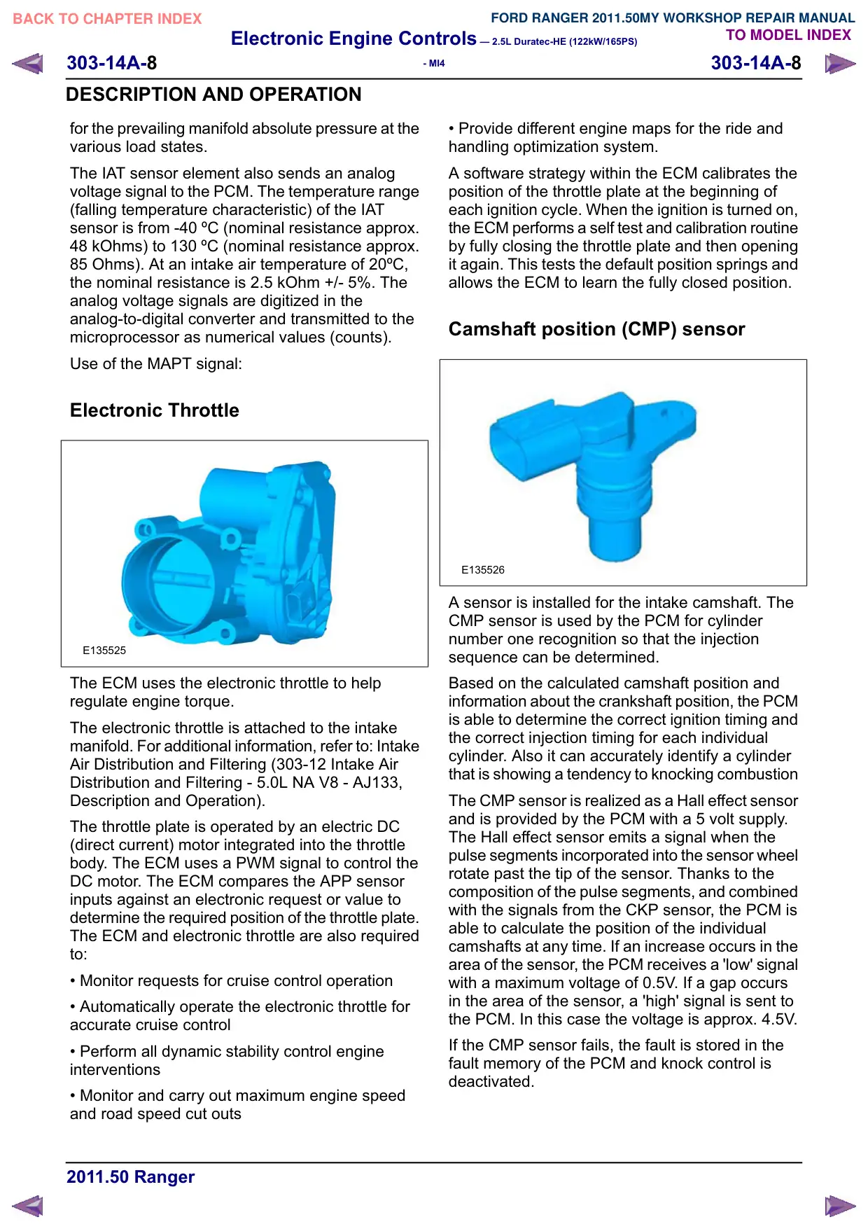
E135522
The heated oxygen sensors allow the ECM to
measure the oxygen content of the exhaust gases,
for closed loop control of the fuel:air mixture and
for catalytic converter monitoring.
An upstream heated oxygen sensor is installed in
the outlet of each exhaust manifold, which enables
independent control of the fuel:air mixture for each
cylinder bank. A downstream heated oxygen
sensor is installed in each catalytic converter, which
enables the performance of the catalytic converters
to be optimized and monitored
Oxygen sensors need to operate at high
temperatures in order to function correctly. To
achieve the high temperatures required, the
sensors are fitted with heater elements that are
controlled by a PWM (pulse width modulation)
signal from the ECM. The heater elements are
operated after each engine start, once it has been
calculated that there is no moisture in the exhaust
(between 0 and 2 minutes delay), and also during
low load conditions when the temperature of the
exhaust gases is insufficient to maintain the
required sensor temperature. The PWM duty cycle
is carefully controlled to prevent thermal shock to
cold sensors. A non-functioning heater delays the
sensor‘s readiness for closed loop control and
increases emissions.
The upstream heated oxygen sensors produce a
constant voltage, with a variable current that is
proportional to the lambda ratio. The downstream
heated oxygen sensors produce an output voltage
dependant on the ratio of the exhaust gas oxygen
to the ambient oxygen.
Electronic Engine Controls – 2.5L Duratec-HE (122kW/165PS)
303-14A-7
303-14A-7
- MI4
DESCRIPTION AND OPERATION
The heated oxygen sensors age with mileage,
increasing their response time to switch from rich
to lean and lean to rich. This increase in response
time influences the ECM closed loop control and
leads to progressively increased emissions.
Measuring the period of rich to lean and lean to
rich switching monitors the response rate of the
upstream sensors.
Diagnosis of electrical faults is continually
monitored in both the upstream and downstream
sensors. This is achieved by checking the signal
against maximum and minimum threshold, for open
and short circuit conditions.
If a heated oxygen sensor fails:
The ECM defaults to open loop fueling for the
related cylinder bank
The CO (carbon monoxide) and emissions content
of the exhaust gases may increase
The exhaust may smell of rotten eggs (hydrogen
sulphide).
With a failed heated oxygen sensor, the engine will
suffer from reduced refinement and performance.
Engine coolant temperature (ECT)
sensor
E135523
The ECT sensors are NTC (negative temperature
coefficient) thermostats that allow the ECM to
monitor the engine coolant temperature.
There are two identical ECT sensors installed,
which are identified as ECT 1 and ECT 2. Each
sensor is secured with a twist-lock and latch
mechanism, and is sealed with an O-ring. A two
pin electrical connector provides the interface
between the sensor and the engine harness
ECT 1
ECT 1 is installed in the heater manifold, at the
rear of the RH (right-hand) cylinder head. The input
from this sensor is used in calibration tables and
by other systems.
If there is an ECT 1 fault, the ECM adopts an
estimated coolant temperature. On the second
consecutive trip with an ECT 1 fault, the ECM
illuminates the MIL (malfunction indicator lamp).
ECT 2
ECT 2 is installed in the lower hose connector
which attaches to the bottom of the thermostat.
The input from this sensor is used for OBD
(on-board diagnostic) 2 diagnostics and, in
conjunction with the input from ECT 1, to confirm
that the thermostat is functional.
If there is an ECT 2 fault, the ECM illuminates the
MIL on the second consecutive trip.
Manifold absolute pressure and
Temperature (MAPT) sensor
E135524
In the MAPT sensor housing are located a
piezo-pressure sensor element (MAP (manifold
absolute pressure) sensor) and the electronic
circuits for signal amplification and temperature
compensation. The IAT sensor element is an NTC
(negative temperature coefficient) resistor. A
special coating process renders the MAP and IAT
sensor elements resistant to damp and humidity
in the intake pipe. The MAPT sensor receives a
reference voltage of 5 Volts from the PCM. The
output signal from the MAP sensor element is an
analogue voltage signal which changes
proportionately to the absolute pressure in the
intake manifold. A high absolute pressure in the
intake manifold (throttle valve wide open) means
a high voltage, and a low absolute pressure in the
intake manifold (throttle valve closed) means a low
voltage. With ignition on and wide-open throttle the
MAP sensor measures the BARO (barometric
pressure). The resulting value is stored in the Keep
Alive Memory and serves as a reference pressure
Electronic Engine Controls – 2.5L Duratec-HE (122kW/165PS)
303-14A-8
303-14A-8
- MI4
DESCRIPTION AND OPERATION
for the prevailing manifold absolute pressure at the
various load states.
The IAT sensor element also sends an analog
voltage signal to the PCM. The temperature range
(falling temperature characteristic) of the IAT
sensor is from -40 ºC (nominal resistance approx.
48 kOhms) to 130 ºC (nominal resistance approx.
85 Ohms). At an intake air temperature of 20ºC,
the nominal resistance is 2.5 kOhm +/- 5%. The
analog voltage signals are digitized in the
analog-to-digital converter and transmitted to the
microprocessor as numerical values (counts).
Use of the MAPT signal:
Electronic Throttle
E135525
The ECM uses the electronic throttle to help
regulate engine torque.
The electronic throttle is attached to the intake
manifold. For additional information, refer to: Intake
Air Distribution and Filtering (303-12 Intake Air
Distribution and Filtering - 5.0L NA V8 - AJ133,
Description and Operation).
The throttle plate is operated by an electric DC
(direct current) motor integrated into the throttle
body. The ECM uses a PWM signal to control the
DC motor. The ECM compares the APP sensor
inputs against an electronic request or value to
determine the required position of the throttle plate.
The ECM and electronic throttle are also required
to:
• Monitor requests for cruise control operation
• Automatically operate the electronic throttle for
accurate cruise control
• Perform all dynamic stability control engine
interventions
• Monitor and carry out maximum engine speed
and road speed cut outs
• Provide different engine maps for the ride and
handling optimization system.
A software strategy within the ECM calibrates the
position of the throttle plate at the beginning of
each ignition cycle. When the ignition is turned on,
the ECM performs a self test and calibration routine
by fully closing the throttle plate and then opening
it again. This tests the default position springs and
allows the ECM to learn the fully closed position.
Camshaft position (CMP) sensor
E135526
A sensor is installed for the intake camshaft. The
CMP sensor is used by the PCM for cylinder
number one recognition so that the injection
sequence can be determined.
Based on the calculated camshaft position and
information about the crankshaft position, the PCM
is able to determine the correct ignition timing and
the correct injection timing for each individual
cylinder. Also it can accurately identify a cylinder
that is showing a tendency to knocking combustion
The CMP sensor is realized as a Hall effect sensor
and is provided by the PCM with a 5 volt supply.
The Hall effect sensor emits a signal when the
pulse segments incorporated into the sensor wheel
rotate past the tip of the sensor. Thanks to the
composition of the pulse segments, and combined
with the signals from the CKP sensor, the PCM is
able to calculate the position of the individual
camshafts at any time. If an increase occurs in the
area of the sensor, the PCM receives a 'low' signal
with a maximum voltage of 0.5V. If a gap occurs
in the area of the sensor, a 'high' signal is sent to
the PCM. In this case the voltage is approx. 4.5V.
If the CMP sensor fails, the fault is stored in the
fault memory of the PCM and knock control is
deactivated.
Electronic Engine Controls – 2.5L Duratec-HE (122kW/165PS)
303-14A-
303-14A-
- MI4
DESCRIPTION AND OPERATION
On vehicles without a CMP sensor, cylinder no. 1
is recognized using the different current rises of
the two sparked cylinders 1 and 3.
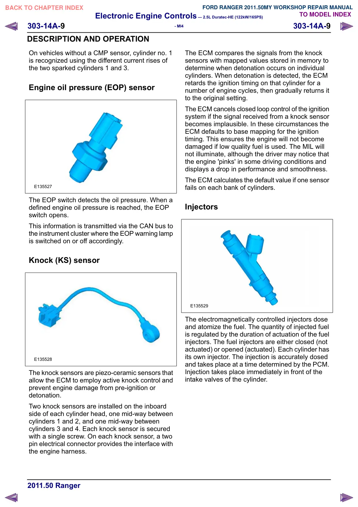
Engine oil pressure (EOP) sensor
E135527
The EOP switch detects the oil pressure. When a
defined engine oil pressure is reached, the EOP
switch opens.
This information is transmitted via the CAN bus to
the instrument cluster where the EOP warning lamp
is switched on or off accordingly.
Knock (KS) sensor
E135528
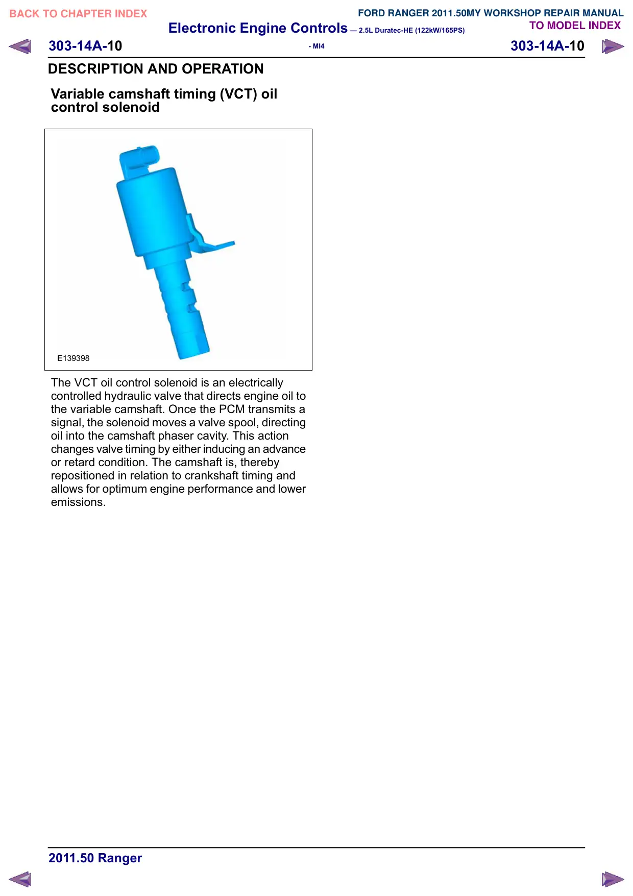
The knock sensors are piezo-ceramic sensors that
allow the ECM to employ active knock control and
prevent engine damage from pre-ignition or
detonation.
Two knock sensors are installed on the inboard
side of each cylinder head, one mid-way between
cylinders 1 and 2, and one mid-way between
cylinders 3 and 4. Each knock sensor is secured
with a single screw. On each knock sensor, a two
pin electrical connector provides the interface with
the engine harness.
The ECM compares the signals from the knock
sensors with mapped values stored in memory to
determine when detonation occurs on individual
cylinders. When detonation is detected, the ECM
retards the ignition timing on that cylinder for a
number of engine cycles, then gradually returns it
to the original setting.
The ECM cancels closed loop control of the ignition
system if the signal received from a knock sensor
becomes implausible. In these circumstances the
ECM defaults to base mapping for the ignition
timing. This ensures the engine will not become
damaged if low quality fuel is used. The MIL will
not illuminate, although the driver may notice that
the engine 'pinks' in some driving conditions and
displays a drop in performance and smoothness.
The ECM calculates the default value if one sensor
fails on each bank of cylinders.
Injectors
E135529
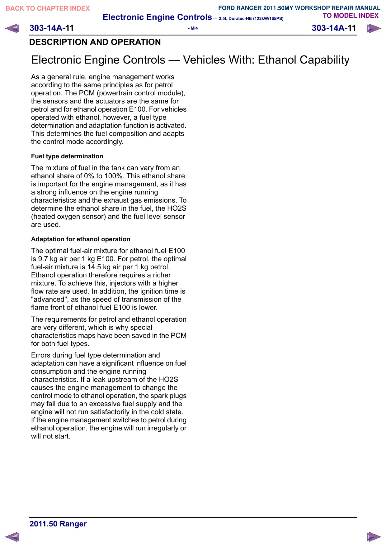
The electromagnetically controlled injectors dose
and atomize the fuel. The quantity of injected fuel
is regulated by the duration of actuation of the fuel
injectors. The fuel injectors are either closed (not
actuated) or opened (actuated). Each cylinder has
its own injector. The injection is accurately dosed
and takes place at a time determined by the PCM.
Injection takes place immediately in front of the
intake valves of the cylinder.
Electronic Engine Controls – 2.5L Duratec-HE (122kW/165PS)
303-14A-10
303-14A-10
- MI4
DESCRIPTION AND OPERATION
Variable camshaft timing (VCT) oil
control solenoid
E139398
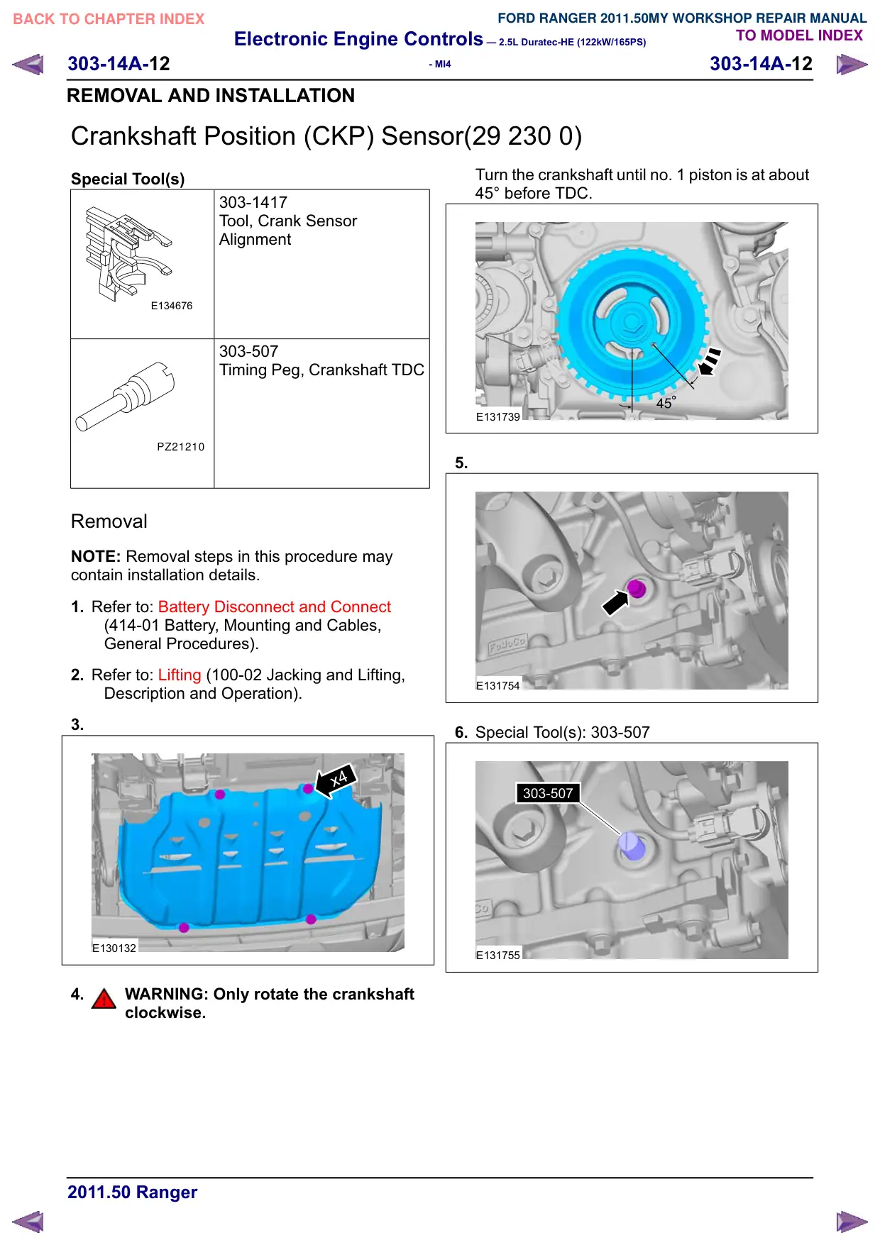
The VCT oil control solenoid is an electrically
controlled hydraulic valve that directs engine oil to
the variable camshaft. Once the PCM transmits a
signal, the solenoid moves a valve spool, directing
oil into the camshaft phaser cavity. This action
changes valve timing by either inducing an advance
or retard condition. The camshaft is, thereby
repositioned in relation to crankshaft timing and
allows for optimum engine performance and lower
emissions.
Electronic Engine Controls – 2.5L Duratec-HE (122kW/165PS)
303-14A-11
303-14A-11
- MI4
DESCRIPTION AND OPERATION
Electronic Engine Controls – Vehicles With: Ethanol Capability
As a general rule, engine management works
according to the same principles as for petrol
operation. The PCM (powertrain control module),
the sensors and the actuators are the same for
petrol and for ethanol operation E100. For vehicles
operated with ethanol, however, a fuel type
determination and adaptation function is activated.
This determines the fuel composition and adapts
the control mode accordingly.
Fuel type determination
The mixture of fuel in the tank can vary from an
ethanol share of 0% to 100%. This ethanol share
is important for the engine management, as it has
a strong influence on the engine running
characteristics and the exhaust gas emissions. To
determine the ethanol share in the fuel, the HO2S
(heated oxygen sensor) and the fuel level sensor
are used.
Adaptation for ethanol operation
The optimal fuel-air mixture for ethanol fuel E100
is 9.7 kg air per 1 kg E100. For petrol, the optimal
fuel-air mixture is 14.5 kg air per 1 kg petrol.
Ethanol operation therefore requires a richer
mixture. To achieve this, injectors with a higher
flow rate are used. In addition, the ignition time is
"advanced", as the speed of transmission of the
flame front of ethanol fuel E100 is lower.
The requirements for petrol and ethanol operation
are very different, which is why special
characteristics maps have been saved in the PCM
for both fuel types.
Errors during fuel type determination and
adaptation can have a significant influence on fuel
consumption and the engine running
characteristics. If a leak upstream of the HO2S
causes the engine management to change the
control mode to ethanol operation, the spark plugs
may fail due to an excessive fuel supply and the
engine will not run satisfactorily in the cold state.
If the engine management switches to petrol during
ethanol operation, the engine will run irregularly or
will not start.
Electronic Engine Controls – 2.5L Duratec-HE (122kW/165PS)
303-14A-12
303-14A-12
- MI4
REMOVAL AND INSTALLATION
Crankshaft Position (CKP) Sensor(29 230 0)
Special Tool(s)
303-1417
Tool, Crank Sensor
Alignment
E134676
303-507
Timing Peg, Crankshaft TDC
PZ21210
Removal
NOTE: Removal steps in this procedure may
contain installation details.
1. Refer to: Battery Disconnect and Connect
(414-01 Battery, Mounting and Cables,
General Procedures).
2. Refer to: Lifting (100-02 Jacking and Lifting,
Description and Operation).
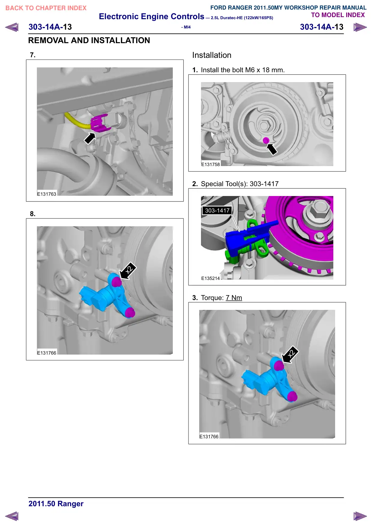
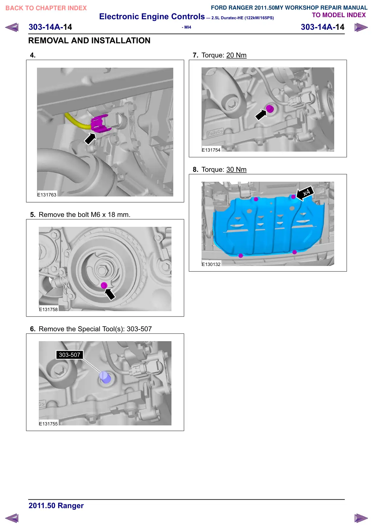
3.
x4
E130132
4.
WARNING: Only rotate the crankshaft
clockwise.
Turn the crankshaft until no. 1 piston is at about
45° before TDC.
E131739
5.
E131754
6. Special Tool(s): 303-507
303-507
E131755
Electronic Engine Controls – 2.5L Duratec-HE (122kW/165PS)
303-14A-15
303-14A-15
- MI4
REMOVAL AND INSTALLATION
Powertrain Control Module (PCM)(29 200 0)
General Equipment
Ford Diagnostic Equipment
Removal
CAUTION: If a new PCM is to be installed,
upload the PCM configuration information
using the Programmable Modules
Installation Routine, prior to commencing
the removal of the PCM.
NOTE: Removal steps in this procedure may
contain installation details.
All vehicles
1. Refer to: Battery Disconnect and Connect
(414-01 Battery, Mounting and Cables,
General Procedures).
2. Refer to: Battery (414-01 Battery, Mounting and
Cables, Removal and Installation).
3. Refer to: Battery Tray (414-01 Battery, Mounting
and Cables, Removal and Installation).
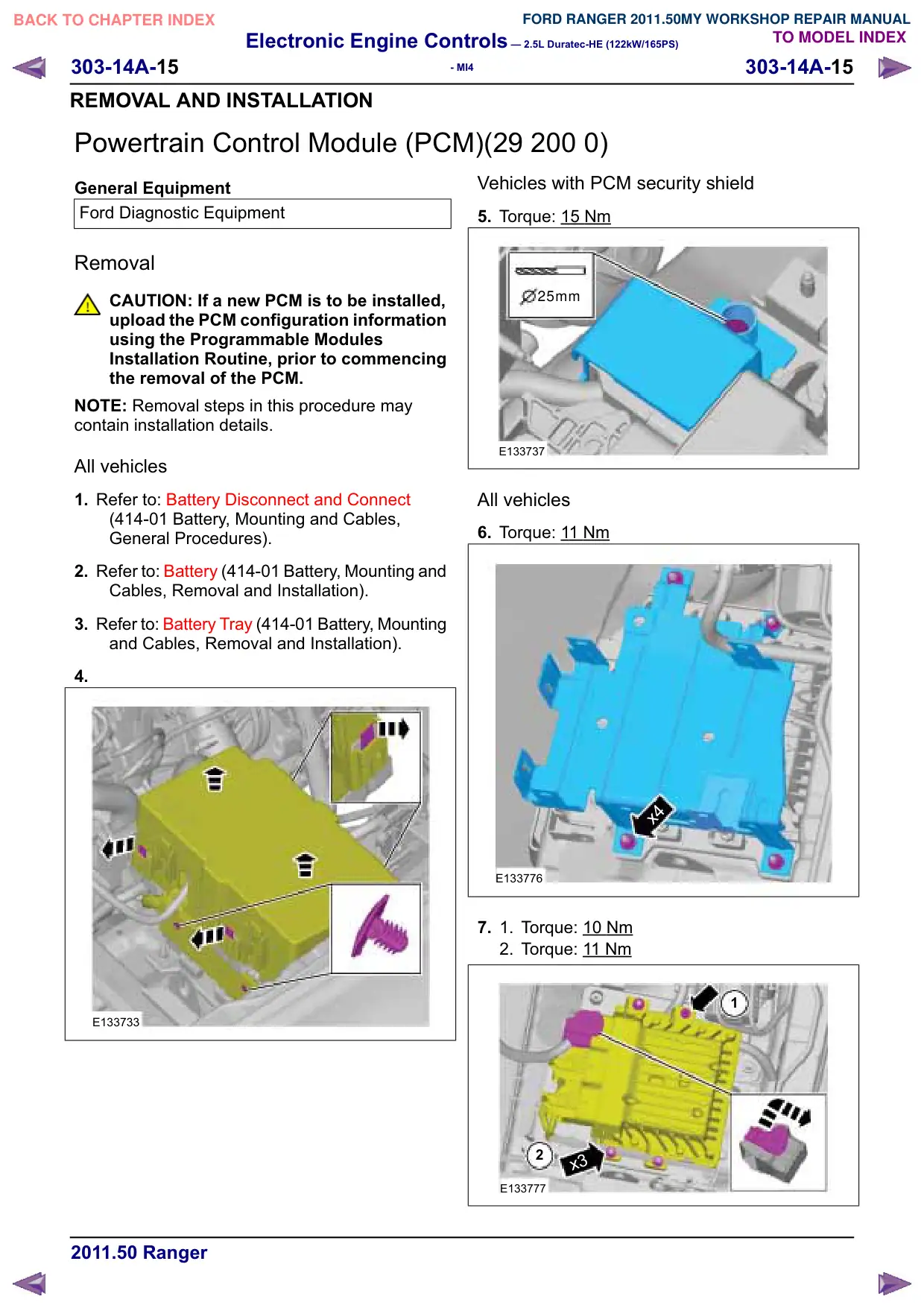
4.
E133733
Vehicles with PCM security shield
5. Torque: 15
Nm
25mm
E133737
All vehicles
6. Torque: 1
1 Nm
x4
E133776
7.
1.
Torque: 10 Nm
2. Torque: 11 Nm
1
2
x3
E133777
Electronic Engine Controls – 2.5L Duratec-HE (122kW/165PS)
303-14A-16
303-14A-16
- MI4
REMOVAL AND INSTALLATION
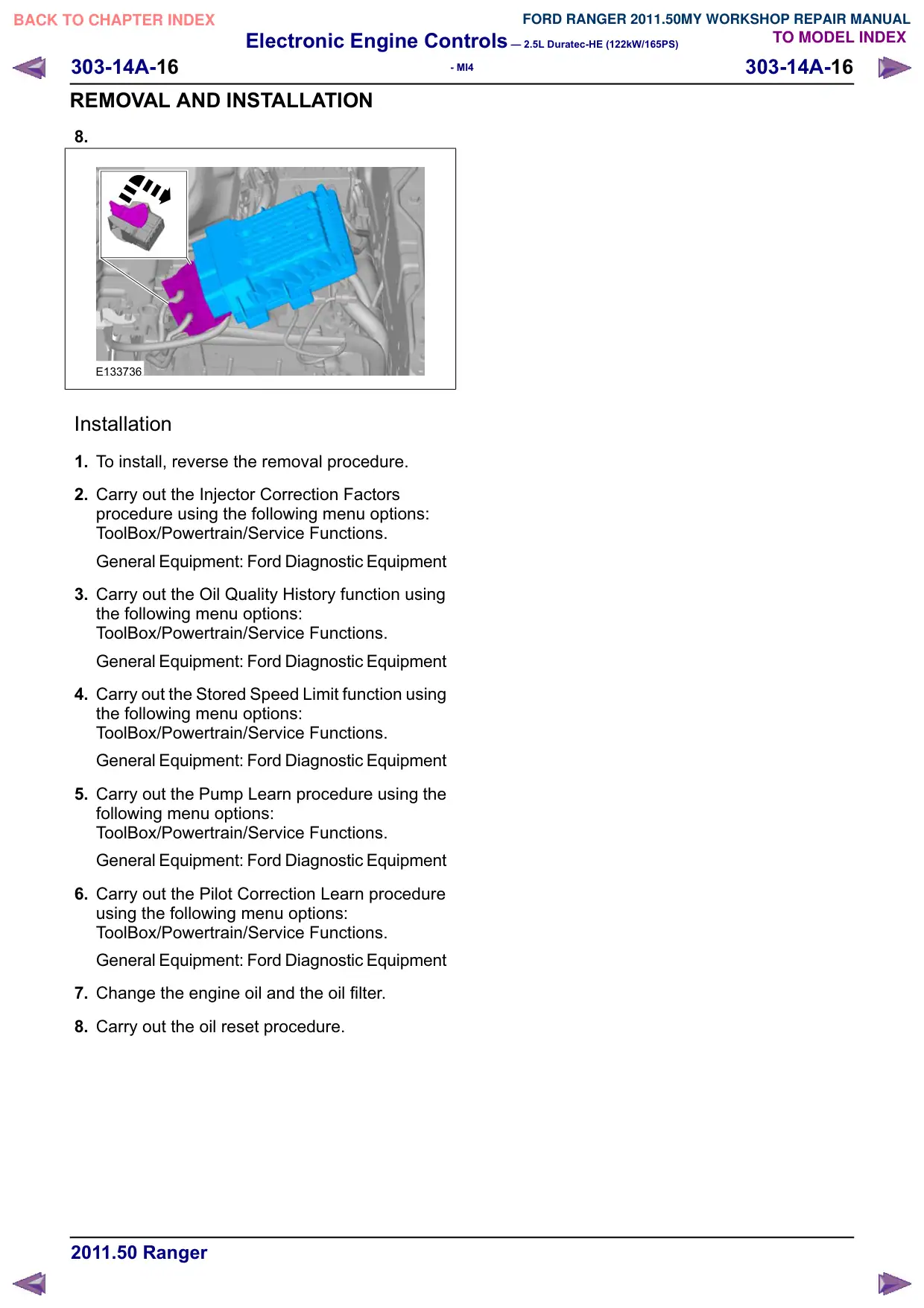
8.
E133736
Installation
1. To install, reverse the removal procedure.
2. Carry out the Injector Correction Factors
procedure using the following menu options:
ToolBox/Powertrain/Service Functions.
General Equipment: Ford Diagnostic Equipment
3. Carry out the Oil Quality History function using
the following menu options:
ToolBox/Powertrain/Service Functions.
General Equipment: Ford Diagnostic Equipment
4. Carry out the Stored Speed Limit function using
the following menu options:
ToolBox/Powertrain/Service Functions.
General Equipment: Ford Diagnostic Equipment
5. Carry out the Pump Learn procedure using the
following menu options:
ToolBox/Powertrain/Service Functions.
General Equipment: Ford Diagnostic Equipment
6. Carry out the Pilot Correction Learn procedure
using the following menu options:
ToolBox/Powertrain/Service Functions.
General Equipment: Ford Diagnostic Equipment
7. Change the engine oil and the oil filter.
8. Carry out the oil reset procedure.
Electronic Engine Controls – 2.5L Duratec-HE (122kW/165PS)
303-14A-17
303-14A-17
- MI4
REMOVAL AND INSTALLATION
Camshaft Position (CMP) Sensor(29 232 0)
Removal
NOTE: Removal steps in this procedure may
contain installation details.
1. Refer to: Battery Disconnect and Connect
(414-01 Battery, Mounting and Cables,
General Procedures).
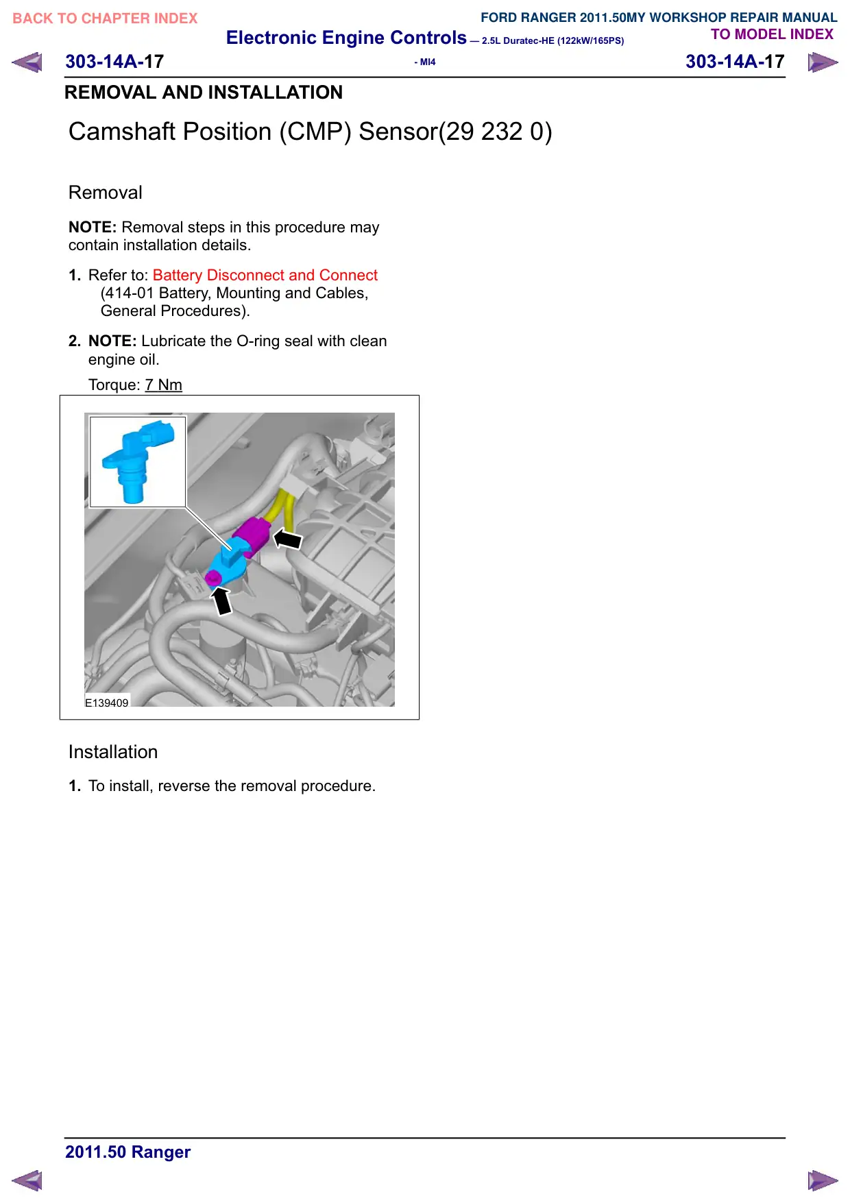
2. NOTE: Lubricate the O-ring seal with clean
engine oil.
Torque: 7 Nm
E139409
Installation
1. To install, reverse the removal procedure.
Electronic Engine Controls – 2.5L Duratec-HE (122kW/165PS)
303-14A-18
303-14A-18
- MI4
REMOVAL AND INSTALLATION
Engine Coolant Temperature (ECT) Sensor(21 190 0)
Removal
NOTE: Removal steps in this procedure may
contain installation details.
1. Refer to: Battery Disconnect and Connect
(414-01 Battery, Mounting and Cables,
General Procedures).
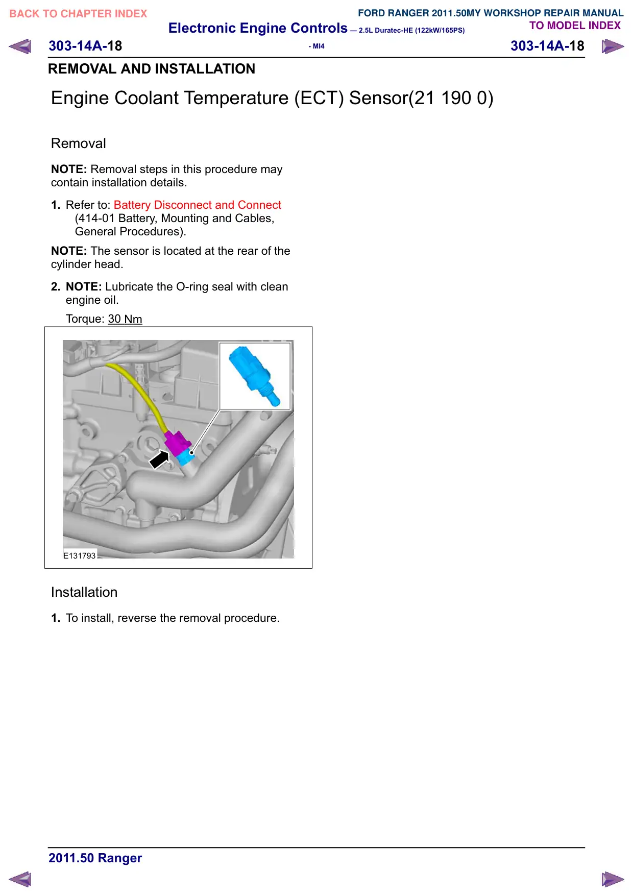
NOTE: The sensor is located at the rear of the
cylinder head.
2. NOTE: Lubricate the O-ring seal with clean
engine oil.
Torque: 30 Nm
E131793
Installation
1. To install, reverse the removal procedure.
Electronic Engine Controls – 2.5L Duratec-HE (122kW/165PS)
303-14A-19
303-14A-19
- MI4
REMOVAL AND INSTALLATION
Heated Oxygen Sensor (HO2S)(29 220 0)
Removal
NOTE: Removal steps in this procedure may
contain installation details.
1. Refer to: Battery Disconnect and Connect
(414-01 Battery, Mounting and Cables,
General Procedures).
2. Refer to: Lifting (100-02 Jacking and Lifting,
Description and Operation).
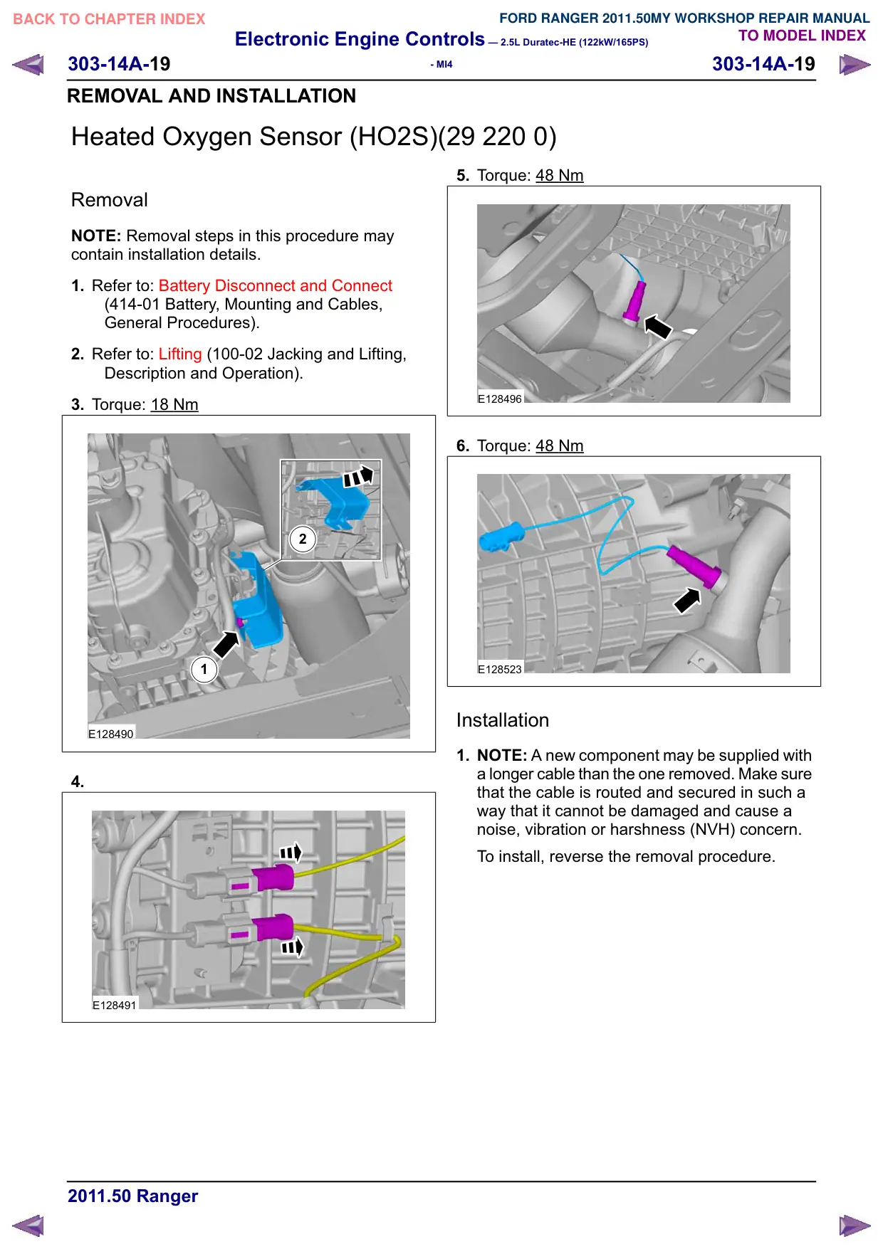
3. Torque: 18 Nm
2
1
E128490
4.
E128491
5. Torque: 48 Nm
E128496
6. Torque: 48 Nm
E128523
Installation
1. NOTE: A new component may be supplied with
a longer cable than the one removed. Make sure
that the cable is routed and secured in such a
way that it cannot be damaged and cause a
noise, vibration or harshness (NVH) concern.
To install, reverse the removal procedure.
Electronic Engine Controls – 2.5L Duratec-HE (122kW/165PS)
303-14A-20
303-14A-20
- MI4
REMOVAL AND INSTALLATION
Knock Sensor (KS)(29 222 0)
Removal
NOTE: Removal steps in this procedure may
contain installation details.
1. Refer to: Battery Disconnect and Connect
(414-01 Battery, Mounting and Cables,
General Procedures).
2. Refer to: Lifting (100-02 Jacking and Lifting,
Description and Operation).
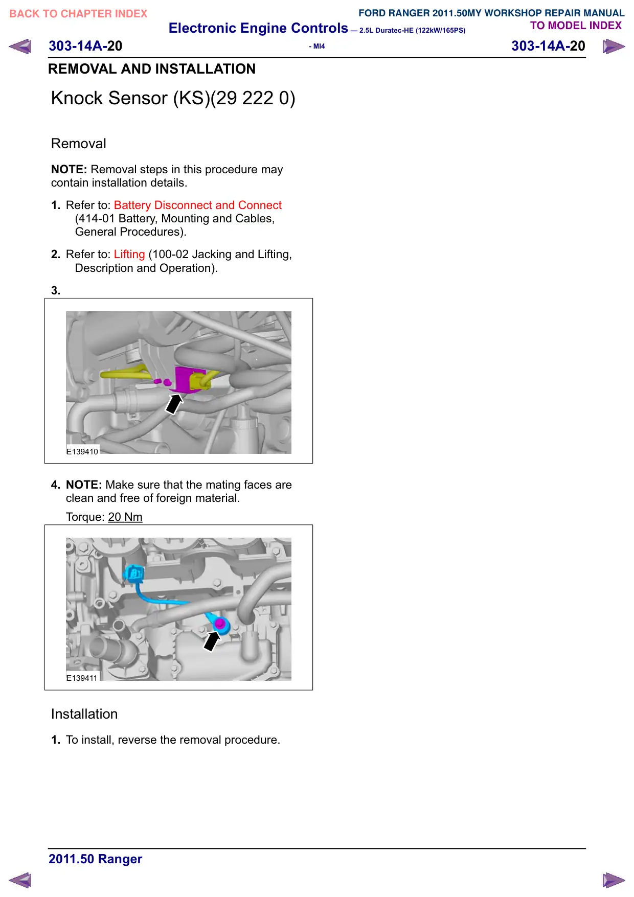
3.
E139410
4. NOTE: Make sure that the mating faces are
clean and free of foreign material.
Torque: 20 Nm
E139411
Installation
1. To install, reverse the removal procedure.
Electronic Engine Controls – 2.5L Duratec-HE (122kW/165PS)
303-14A-21
303-14A-21
- MI4
REMOVAL AND INSTALLATION
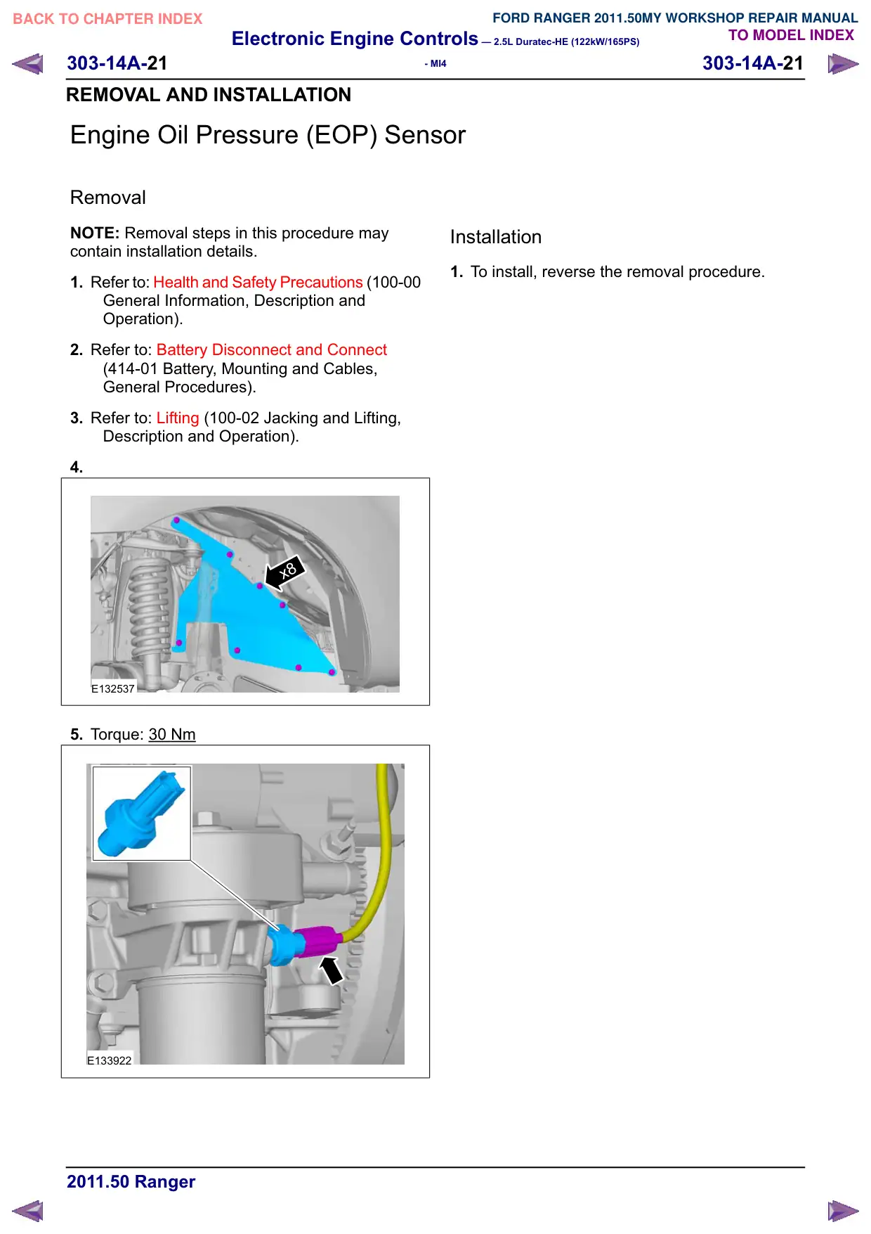
Engine Oil Pressure (EOP) Sensor
Removal
NOTE: Removal steps in this procedure may
contain installation details.
1. Refer to: Health and Safety Precautions (100-00
General Information, Description and
Operation).
2. Refer to: Battery Disconnect and Connect
(414-01 Battery, Mounting and Cables,
General Procedures).
3. Refer to: Lifting (100-02 Jacking and Lifting,
Description and Operation).
4.
x8
E132537
5. Torque: 30 Nm
E133922
Installation
1. To install, reverse the removal procedure.
Electronic Engine Controls – 2.5L Duratec-HE (122kW/165PS)
303-14A-22
303-14A-22
- MI4
REMOVAL AND INSTALLATION
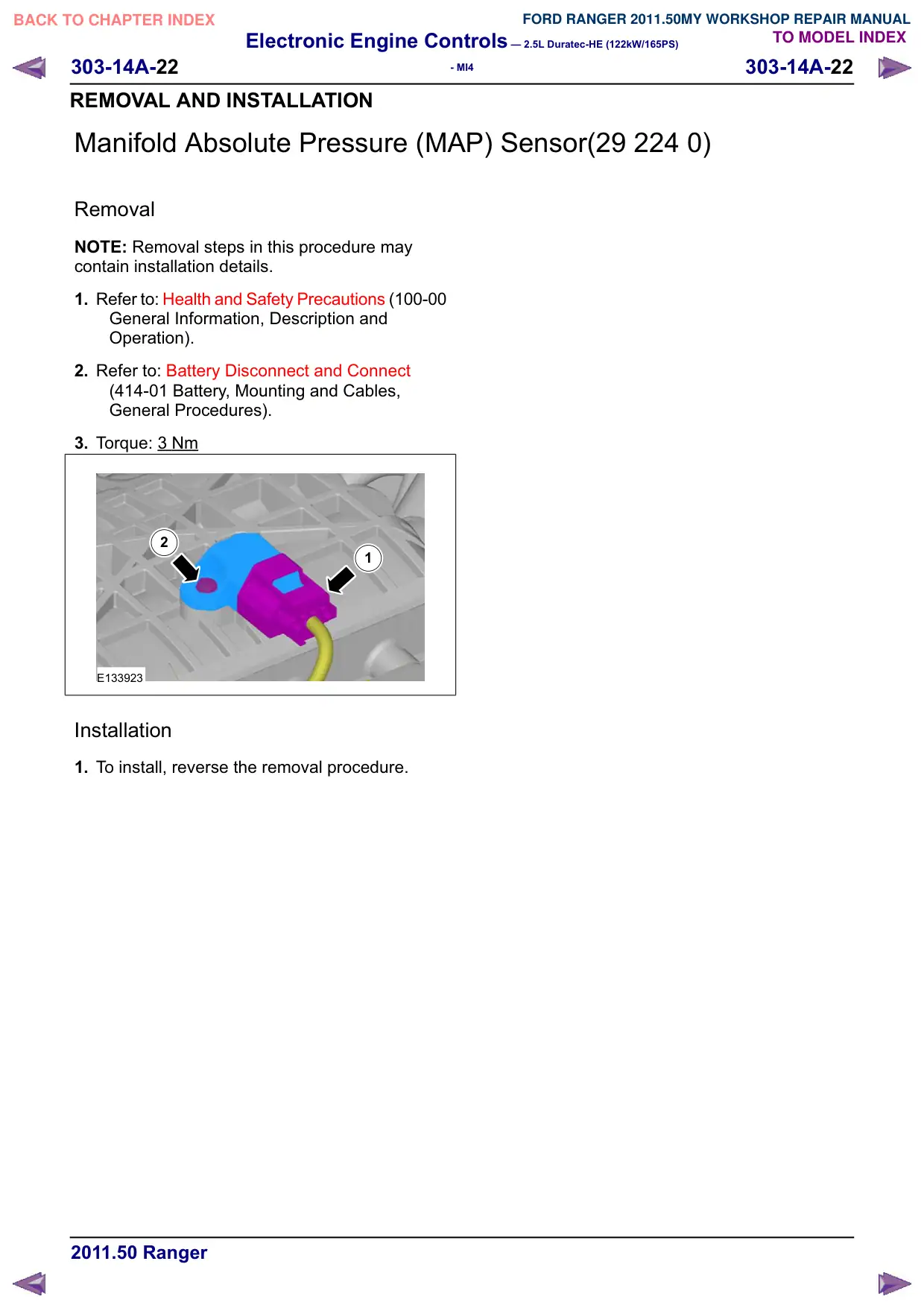
Manifold Absolute Pressure (MAP) Sensor(29 224 0)
Removal
NOTE: Removal steps in this procedure may
contain installation details.
1. Refer to: Health and Safety Precautions (100-00
General Information, Description and
Operation).
2. Refer to: Battery Disconnect and Connect
(414-01 Battery, Mounting and Cables,
General Procedures).
3. Torque: 3 Nm
2
1
E133923
Installation
1. To install, reverse the removal procedure.