Trava da coluna de direção e carcaça do cilindro de ignição
Steering Column Lock and Ignition Switch Housing
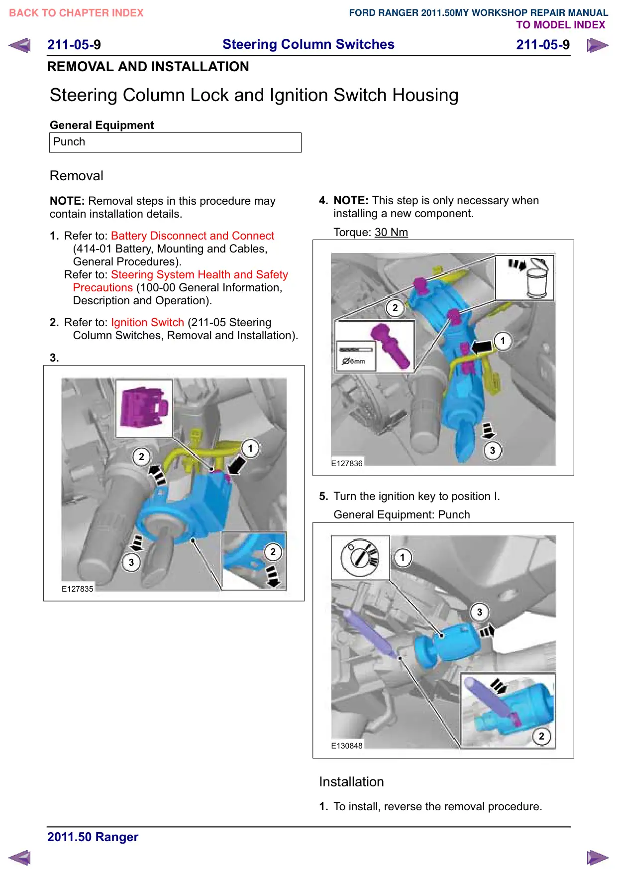
Texto da página
Link desta página: https://ranger.mbrace.com.br/oficina/259
Imagem: https://ranger.mbrace.com.br/img/oficina/259.webp
211-05-
Steering Column Switches
211-05-
REMOVAL AND INSTALLATION
Steering Column Lock and Ignition Switch Housing
General Equipment
Punch
Removal
NOTE: Removal steps in this procedure may
contain installation details.
1. Refer to: Battery Disconnect and Connect
(414-01 Battery, Mounting and Cables,
General Procedures).
Refer to: Steering System Health and Safety
Precautions (100-00 General Information,
Description and Operation).
2. Refer to: Ignition Switch (211-05 Steering
Column Switches, Removal and Installation).
3.
1
2
2
3
E127835
4. NOTE: This step is only necessary when
installing a new component.
Torque: 30
Nm
2
1
3
E127836
5. Turn the ignition key to position I.
General Equipment: Punch
1
3
2
E130848
Installation
1. To install, reverse the removal procedure.