Auxílio de estacionamento
Parking Aid
Texto da página
Link desta página: https://ranger.mbrace.com.br/oficina/1228
Imagem: https://ranger.mbrace.com.br/img/oficina/1228.webp
413-13-
Parking Aid
413-13-
DESCRIPTION AND OPERATION
Item
Description
1
Front inner parking aid sensor(s).
2
Front inner parking aid sensor holder(s).
3
Front outer parking aid sensor(s).
4
Front outer parking aid sensor holder(s).
The parking aid sensor consists of a sensor and a
holder. The holder makes sure that each parking
aid sensor is correctly orientated in relation to its
location in the front bumper.
For additional information, refer to: Front Parking
Aid Sensor (413-13 Parking Aid, Removal and
Installation).
Each parking aid sensor has a three pin connector
which connects with the front bumper wiring
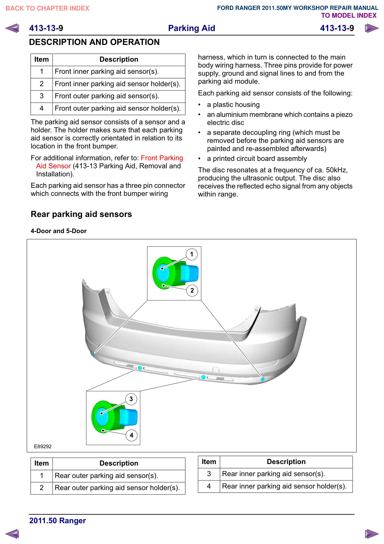
Rear parking aid sensors
4-Door and 5-Door
3
4
E89292
Item
Description
1
Rear outer parking aid sensor(s).
2
Rear outer parking aid sensor holder(s).
harness, which in turn is connected to the main
body wiring harness. Three pins provide for power
supply, ground and signal lines to and from the
parking aid module.
Each parking aid sensor consists of the following:
a plastic housing
an aluminium membrane which contains a piezo
electric disc
a separate decoupling ring (which must be
removed before the parking aid sensors are
painted and re-assembled afterwards)
a printed circuit board assembly
The disc resonates at a frequency of ca. 50kHz,
producing the ultrasonic output. The disc also
receives the reflected echo signal from any objects
within range.
1
2
Item
Description
3
Rear inner parking aid sensor(s).
4
Rear inner parking aid sensor holder(s).