Tanque de combustível e tubulações
Fuel Tank and Lines
Texto da página
Link desta página: https://ranger.mbrace.com.br/oficina/1149
Imagem: https://ranger.mbrace.com.br/img/oficina/1149.webp
Fuel Tank and Lines – 2.2L Duratorq-TDCi (88kW/120PS) - Puma/2.2L
Duratorq-TDCi (96kW/130PS) - Puma/2.2L Duratorq-TDCi (110kW/150PS) - Puma/3.2L
310-01B-4
310-01B-4
Duratorq-TDCi (148kW/200PS) - Puma
DESCRIPTION AND OPERATION
Item
Description
13
Breather pipe
14
Fuel tank filler pipe
15
Fuel cooler
Fuel tank vent valves
E128985
Fuel tank ventilation is achieved by two fuel tank
vent valves. The fuel tank vent valves are integral
to the fuel tank and will prevent fuel loss from the
fuel tank if the vehicle becomes inverted.
Under normal working conditions, the pressure
within the fuel tank is controlled by allowing the
fuel vapor to vent through the fuel tank vent valves
to atmosphere. If the fuel tank becomes inverted,
the fuel tank vent valves close preventing fuel being
lost from the fuel tank.
If the fuel tank vent valves or the fuel vapor lines
connected to the vent valves become restricted,
vehicle performance will become impaired. The
inability of the fuel tank to substitute the fuel
demanded by the fuel charging system with air,
will create a negative pressure in the fuel tank
which will result in reduced fuel flow to the fuel
pump.
Fuel Level sensor
1
1
2
2
5
5
4
4
3
3
E128986
Item
Description
1
Fuel level sensor locking ring
2
Fuel level sensor resistor card
3
Fuel jet pump and filter
4
Fuel level sensor sealing ring
5
Fuel fired booster heater fuel pickup
connector
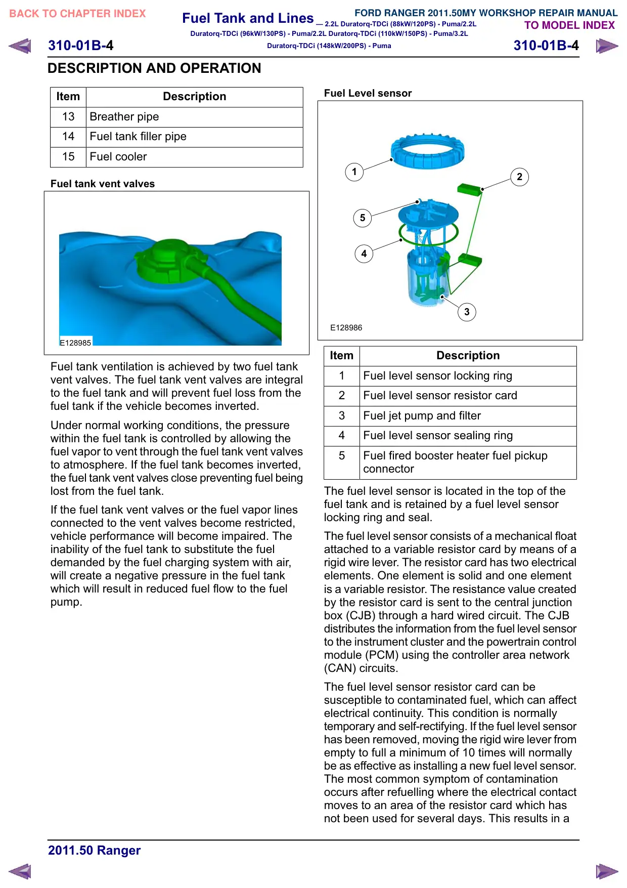
The fuel level sensor is located in the top of the
fuel tank and is retained by a fuel level sensor
locking ring and seal.
The fuel level sensor consists of a mechanical float
attached to a variable resistor card by means of a
rigid wire lever. The resistor card has two electrical
elements. One element is solid and one element
is a variable resistor. The resistance value created
by the resistor card is sent to the central junction
box (CJB) through a hard wired circuit. The CJB
distributes the information from the fuel level sensor
to the instrument cluster and the powertrain control
module (PCM) using the controller area network
(CAN) circuits.
The fuel level sensor resistor card can be
susceptible to contaminated fuel, which can affect
electrical continuity. This condition is normally
temporary and self-rectifying. If the fuel level sensor
has been removed, moving the rigid wire lever from
empty to full a minimum of 10 times will normally
be as effective as installing a new fuel level sensor.
The most common symptom of contamination
occurs after refuelling where the electrical contact
moves to an area of the resistor card which has
not been used for several days. This results in a