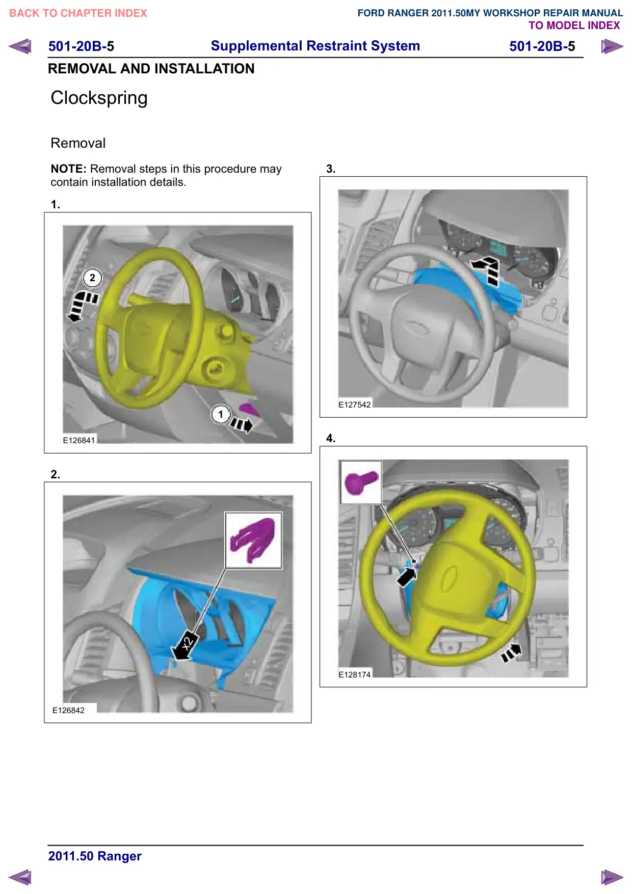
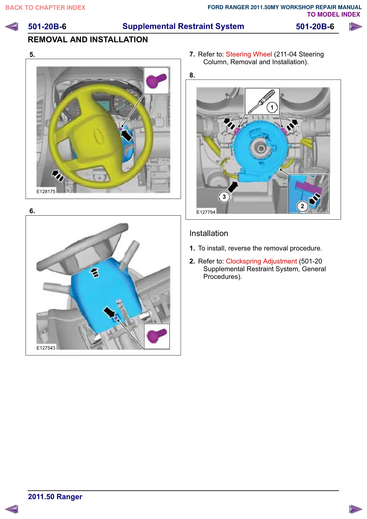
501-20B-1
501-20B-1
Supplemental Restraint System
REMOVAL AND INSTALLATION
Driver Air Bag Module
General Equipment
Flat Headed Screw Driver
Removal
WARNING: The supplemental restraint
system (SRS) is active for a certain length
of time after the power supply has been
disconnected. Wait for a minimum of 3
minutes before disconnecting or removing
any SRS components.
NOTE: Removal steps in this procedure may
contain installation details.
1. Refer to: Supplemental Restraint System (SRS)
Health and Safety Precautions (100-00
General Information, Description and
Operation).
2. Refer to: Battery Disconnect and Connect
(414-01 Battery, Mounting and Cables,
General Procedures).
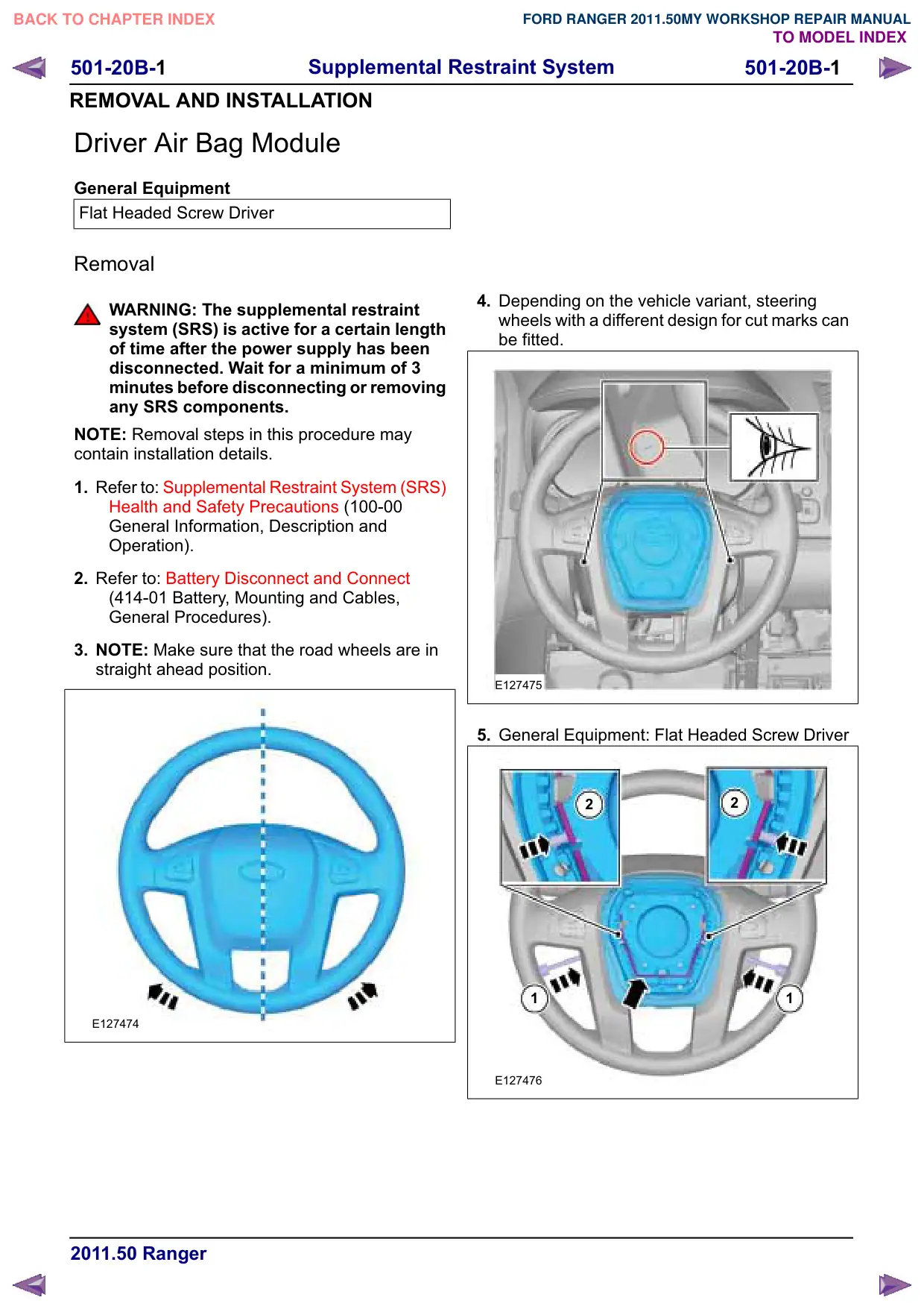
3. NOTE: Make sure that the road wheels are in
straight ahead position.
E127474
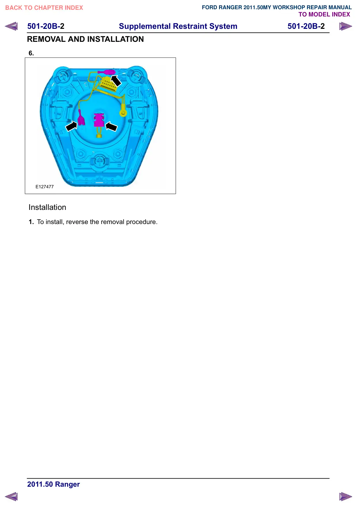
4. Depending on the vehicle variant, steering
wheels with a different design for cut marks can
be fitted.
E127475
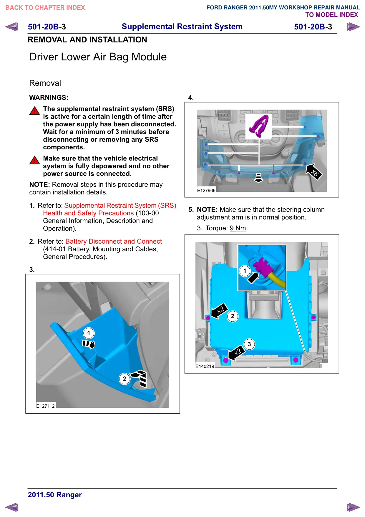
5. General Equipment: Flat Headed Screw Driver
2
2
1
1
E127476
501-20B-3
501-20B-3
Supplemental Restraint System
REMOVAL AND INSTALLATION
Driver Lower Air Bag Module
Removal
WARNINGS:
The supplemental restraint system (SRS)
is active for a certain length of time after
the power supply has been disconnected.
Wait for a minimum of 3 minutes before
disconnecting or removing any SRS
components.
Make sure that the vehicle electrical
system is fully depowered and no other
power source is connected.
NOTE: Removal steps in this procedure may
contain installation details.
1. Refer to: Supplemental Restraint System (SRS)
Health and Safety Precautions (100-00
General Information, Description and
Operation).
2. Refer to: Battery Disconnect and Connect
(414-01 Battery, Mounting and Cables,
General Procedures).
3.
1
2
E127112
4.
x8
E127966
5. NOTE: Make sure that the steering column
adjustment arm is in normal position.
3. Torque: 9 Nm
1
x2
2
3
x2
E140219
501-20B-4
501-20B-4
Supplemental Restraint System
REMOVAL AND INSTALLATION
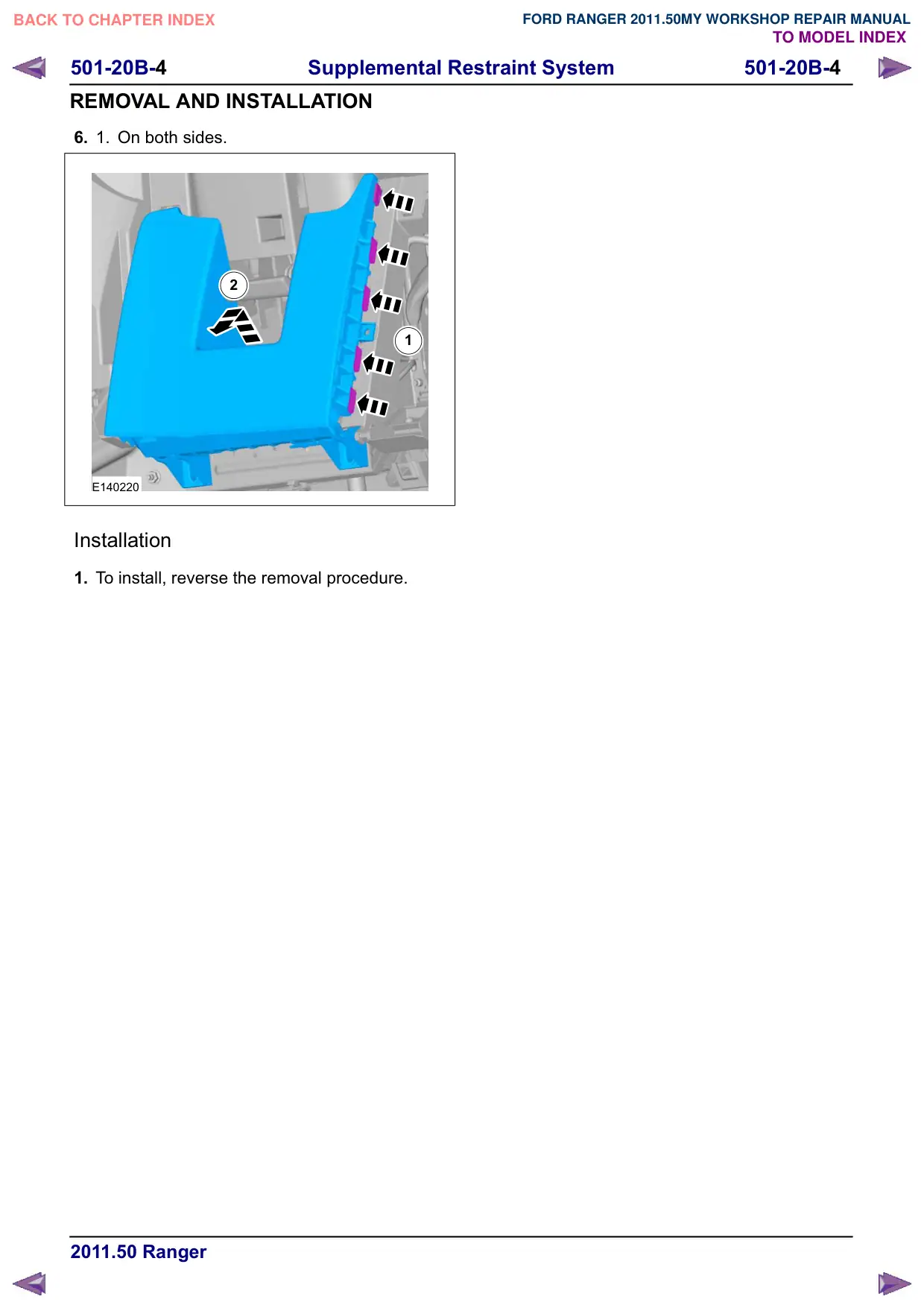
6.
1.
On both sides.
2
1
E140220
Installation
1. To install, reverse the removal procedure.
501-20B-7
501-20B-7
Supplemental Restraint System
GENERAL PROCEDURES
Clockspring Adjustment
General Equipment
Adhesive Tape
WARNINGS:
If there is a break between installing the
clockspring and steering wheel rotation
sensor assembly and installing the
steering wheel, the centralizing of the
clockspring must be repeated.
If the centralization of the clockspring is
in doubt, the centralizing of the clockspring
must be repeated.
NOTE: Make sure that the road wheels are in the
straight ahead position.
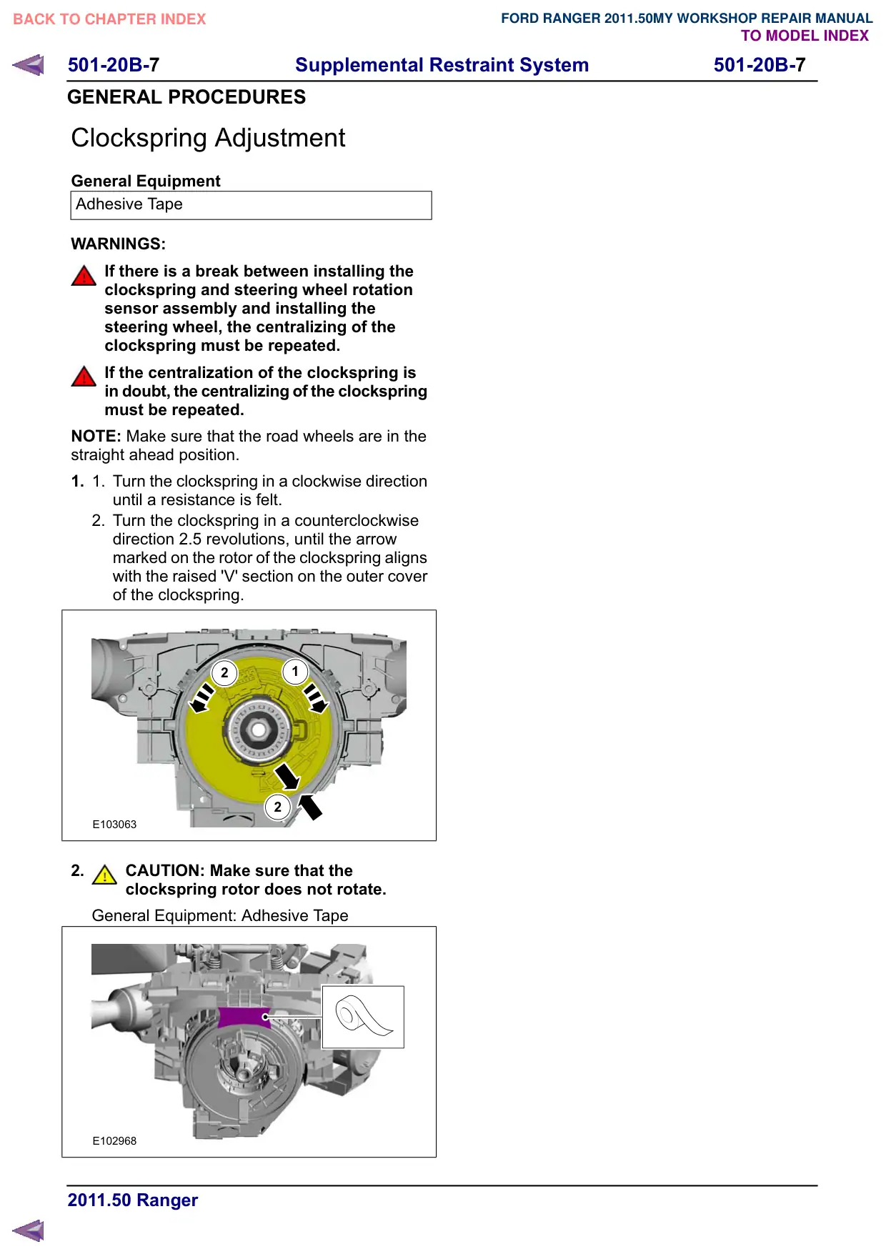
1.
1.
Turn the clockspring in a clockwise direction
until a resistance is felt.
2. Turn the clockspring in a counterclockwise
direction 2.5 revolutions, until the arrow
marked on the rotor of the clockspring aligns
with the raised 'V' section on the outer cover
of the clockspring.
2
1
2
E103063
2.
CAUTION: Make sure that the
clockspring rotor does not rotate.
General Equipment: Adhesive Tape
E102968