Fuel Tank and Lines
310-01A-1
310-01A-1
.
SECTION 310-01A Fuel Tank and Lines
VEHICLE APPLICATION: 2011.50 Ranger
CONTENTS
DESCRIPTION AND OPERATION
Fuel Tank and Lines............................................................................................................
REMOVAL AND INSTALLATION
Fuel Tank............................................................................................................................
Fuel Tank Filler Pipe...........................................................................................................
Fuel Filter............................................................................................................................
Fuel Pump and Sender Unit...............................................................................................
PAGE
310-01A-2
310-01A-6
310-01A-8
310-01A-9
310-01A-10
310-01A-2
Fuel Tank and Lines
310-01A-2
DESCRIPTION AND OPERATION
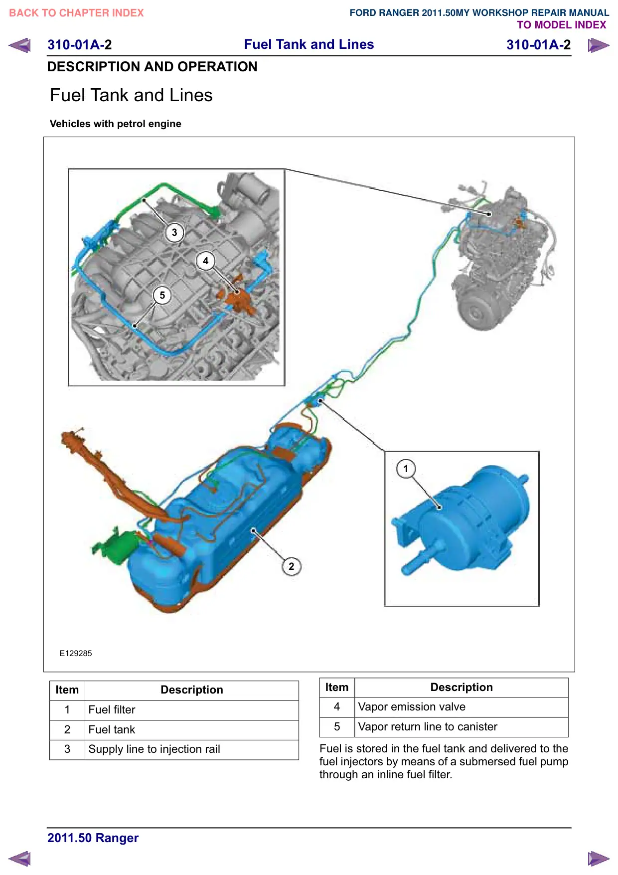
Fuel Tank and Lines
Vehicles with petrol engine
3
4
5
E129285
Item
Description
1
Fuel filter
2
Fuel tank
3
Supply line to injection rail
1
2
Item
Description
4
Vapor emission valve
5
Vapor return line to canister
Fuel is stored in the fuel tank and delivered to the
fuel injectors by means of a submersed fuel pump
through an inline fuel filter.
Fuel Tank and Lines
310-01A-3
310-01A-3
DESCRIPTION AND OPERATION
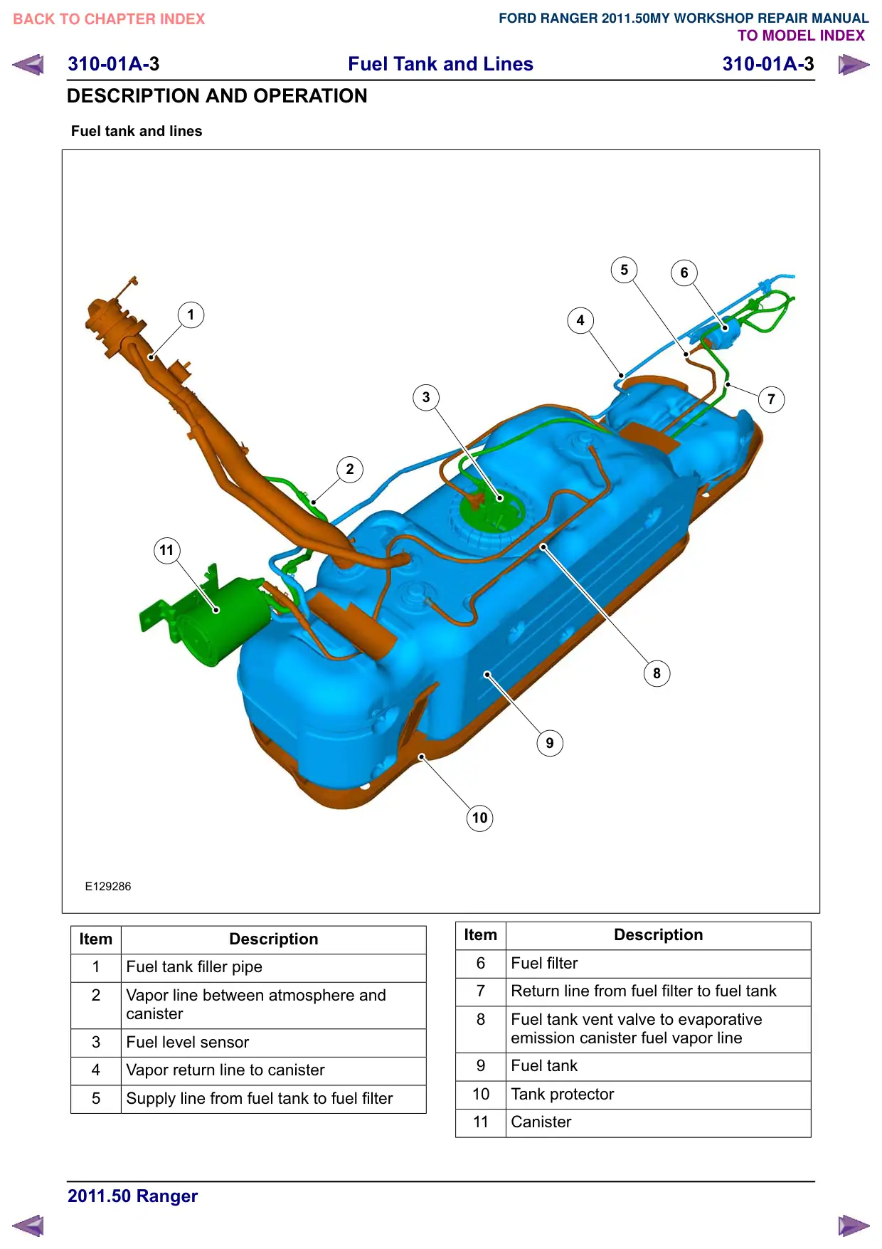
Fuel tank and lines
1
2
11
E129286
Item
Description
1
Fuel tank filler pipe
2
Vapor line between atmosphere and
canister
3
Fuel level sensor
4
Vapor return line to canister
5
Supply line from fuel tank to fuel filter
5
6
4
3
7
8
10
Item
Description
6
Fuel filter
7
Return line from fuel filter to fuel tank
8
Fuel tank vent valve to evaporative
emission canister fuel vapor line
Fuel tank
10
Tank protector
11
Canister
Fuel Tank and Lines
310-01A-4
310-01A-4
DESCRIPTION AND OPERATION
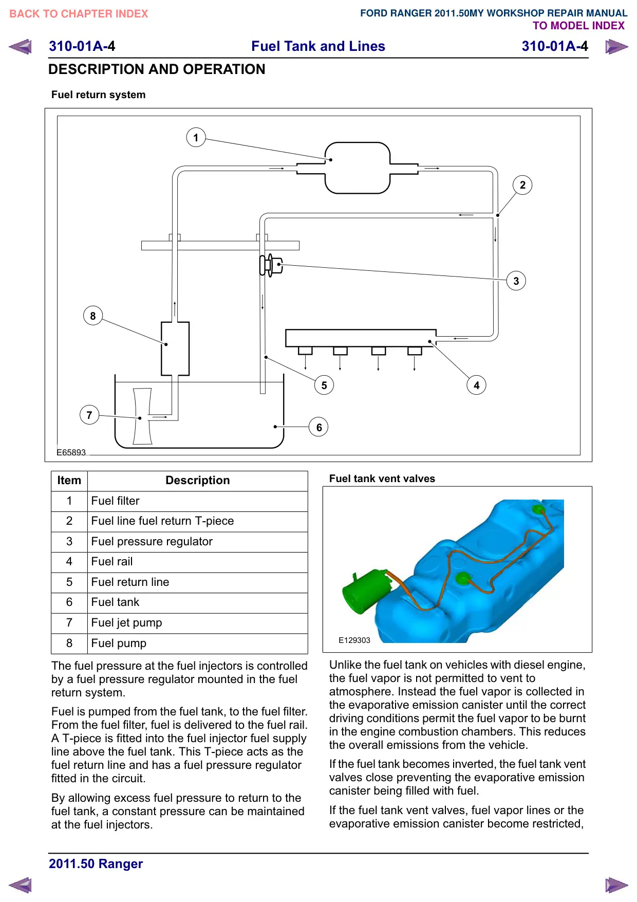
Fuel return system
1
8
7
E65893
Item
Description
1
Fuel filter
2
Fuel line fuel return T-piece
3
Fuel pressure regulator
4
Fuel rail
5
Fuel return line
6
Fuel tank
7
Fuel jet pump
8
Fuel pump
The fuel pressure at the fuel injectors is controlled
by a fuel pressure regulator mounted in the fuel
return system.
Fuel is pumped from the fuel tank, to the fuel filter.
From the fuel filter, fuel is delivered to the fuel rail.
A T-piece is fitted into the fuel injector fuel supply
line above the fuel tank. This T-piece acts as the
fuel return line and has a fuel pressure regulator
fitted in the circuit.
By allowing excess fuel pressure to return to the
fuel tank, a constant pressure can be maintained
at the fuel injectors.
2
3
5
4
6
Fuel tank vent valves
E129303
Unlike the fuel tank on vehicles with diesel engine,
the fuel vapor is not permitted to vent to
atmosphere. Instead the fuel vapor is collected in
the evaporative emission canister until the correct
driving conditions permit the fuel vapor to be burnt
in the engine combustion chambers. This reduces
the overall emissions from the vehicle.
If the fuel tank becomes inverted, the fuel tank vent
valves close preventing the evaporative emission
canister being filled with fuel.
If the fuel tank vent valves, fuel vapor lines or the
evaporative emission canister become restricted,
Fuel Tank and Lines
310-01A-5
310-01A-5
DESCRIPTION AND OPERATION
vehicle performance will become impaired. The
inability of the fuel tank to substitute the fuel
demanded by the fuel pump with air, will create a
negative pressure in the fuel tank which could
result in deformation of the fuel tank.
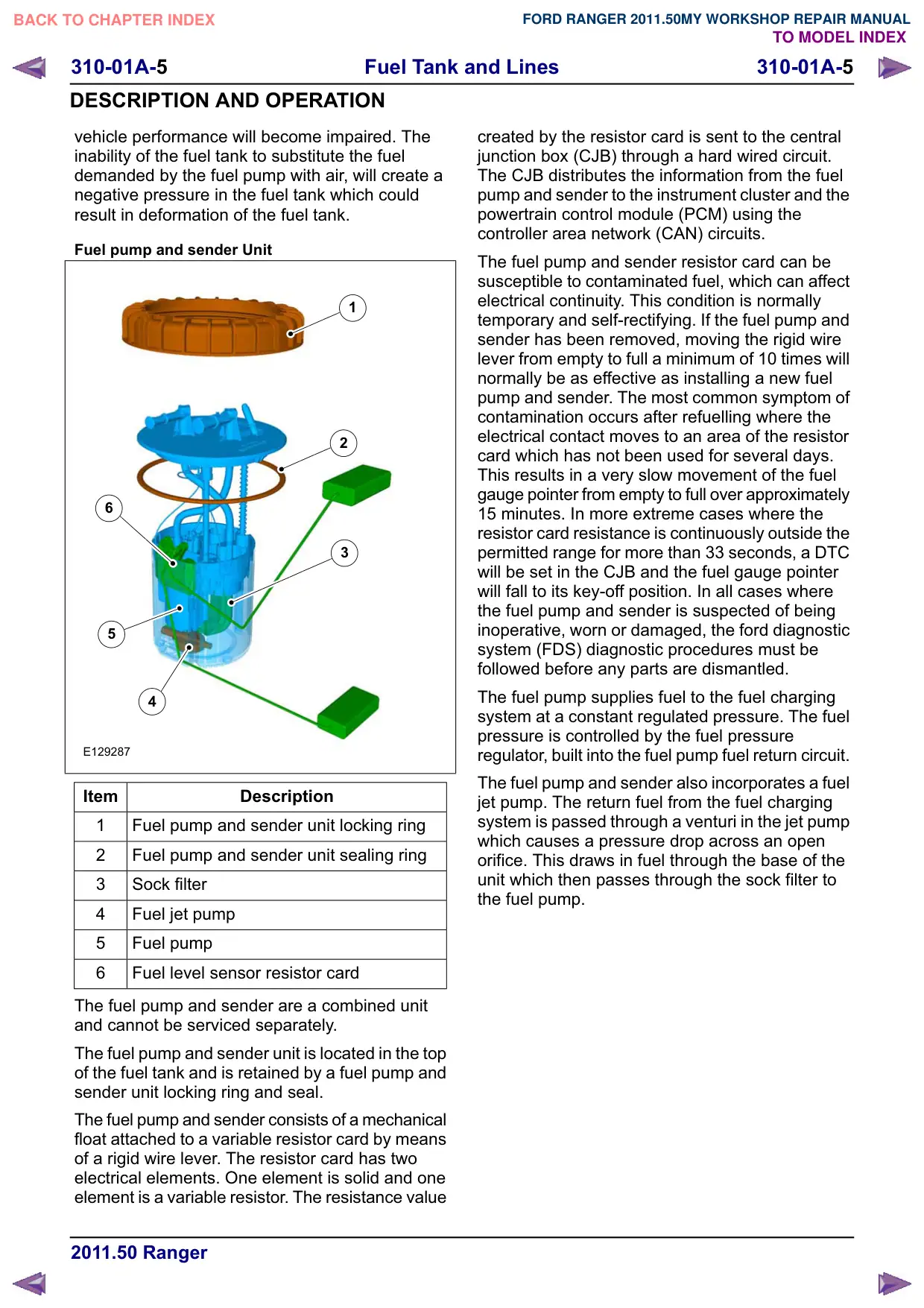
Fuel pump and sender Unit
1
2
6
3
5
4
E129287
Item
Description
1
Fuel pump and sender unit locking ring
2
Fuel pump and sender unit sealing ring
3
Sock filter
4
Fuel jet pump
5
Fuel pump
6
Fuel level sensor resistor card
The fuel pump and sender are a combined unit
and cannot be serviced separately.
The fuel pump and sender unit is located in the top
of the fuel tank and is retained by a fuel pump and
sender unit locking ring and seal.
The fuel pump and sender consists of a mechanical
float attached to a variable resistor card by means
of a rigid wire lever. The resistor card has two
electrical elements. One element is solid and one
element is a variable resistor. The resistance value
created by the resistor card is sent to the central
junction box (CJB) through a hard wired circuit.
The CJB distributes the information from the fuel
pump and sender to the instrument cluster and the
powertrain control module (PCM) using the
controller area network (CAN) circuits.
The fuel pump and sender resistor card can be
susceptible to contaminated fuel, which can affect
electrical continuity. This condition is normally
temporary and self-rectifying. If the fuel pump and
sender has been removed, moving the rigid wire
lever from empty to full a minimum of 10 times will
normally be as effective as installing a new fuel
pump and sender. The most common symptom of
contamination occurs after refuelling where the
electrical contact moves to an area of the resistor
card which has not been used for several days.
This results in a very slow movement of the fuel
gauge pointer from empty to full over approximately
15 minutes. In more extreme cases where the
resistor card resistance is continuously outside the
permitted range for more than 33 seconds, a DTC
will be set in the CJB and the fuel gauge pointer
will fall to its key-off position. In all cases where
the fuel pump and sender is suspected of being
inoperative, worn or damaged, the ford diagnostic
system (FDS) diagnostic procedures must be
followed before any parts are dismantled.
The fuel pump supplies fuel to the fuel charging
system at a constant regulated pressure. The fuel
pressure is controlled by the fuel pressure
regulator, built into the fuel pump fuel return circuit.
The fuel pump and sender also incorporates a fuel
jet pump. The return fuel from the fuel charging
system is passed through a venturi in the jet pump
which causes a pressure drop across an open
orifice. This draws in fuel through the base of the
unit which then passes through the sock filter to
the fuel pump.
Fuel Tank and Lines
310-01A-6
310-01A-6
REMOVAL AND INSTALLATION
Fuel Tank
General Equipment
Transmission Jack
Removal
NOTE: Removal steps in this procedure may
contain installation details.
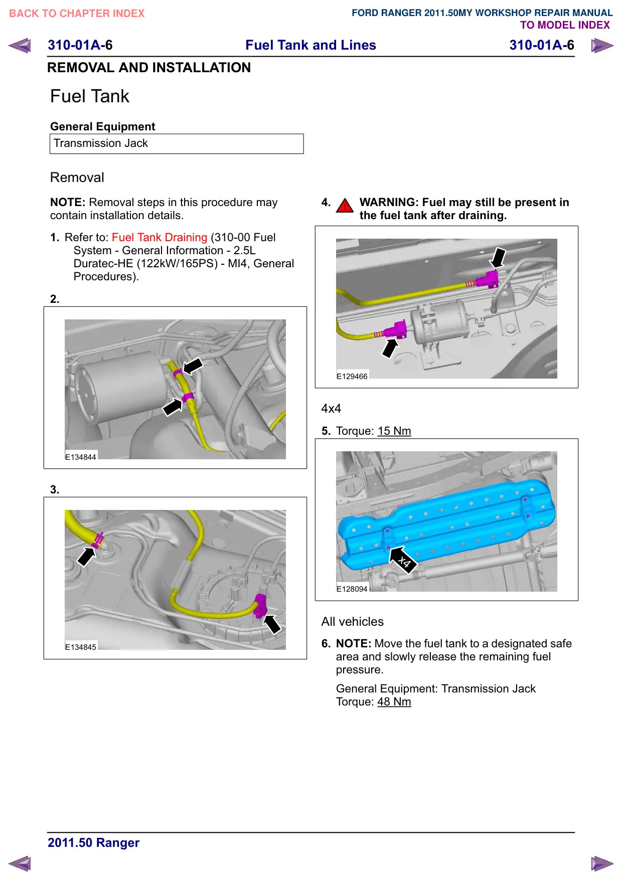
1. Refer to: Fuel Tank Draining (310-00 Fuel
System - General Information - 2.5L
Duratec-HE (122kW/165PS) - MI4, General
Procedures).
2.
E134844
3.
E134845
4.
WARNING: Fuel may still be present in
the fuel tank after draining.
E129466
4x4
5. Torque: 15 Nm
x4
E128094
All vehicles
6. NOTE: Move the fuel tank to a designated safe
area and slowly release the remaining fuel
pressure.
General Equipment: Transmission Jack
Torque: 48 Nm
Fuel Tank and Lines
310-01A-7
310-01A-7
REMOVAL AND INSTALLATION
1
x2
2
E134950
7.
E134846
Installation
1.
CAUTION: If the fuel tank has been filled
with the wrong type of fuel, the engine
must not be started before the fuel
system is cleaned.
NOTE: Fill the fuel tank with petrol fuel.
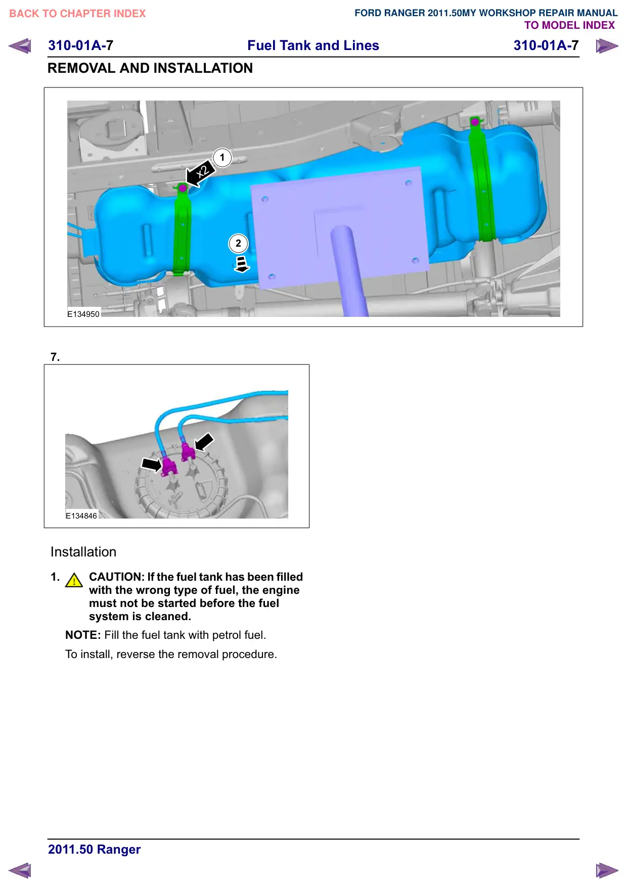
To install, reverse the removal procedure.
Fuel Tank and Lines
310-01A-8
310-01A-8
REMOVAL AND INSTALLATION
Fuel Tank Filler Pipe
Removal
NOTE: Removal steps in this procedure may
contain installation details.
1. Refer to: Fuel Tank Draining (310-00 Fuel
System - General Information - 2.5L
Duratec-HE (122kW/165PS) - MI4, General
Procedures).
Single cab
2.
2.
Torque: 11 Nm
1
2
E134951
All vehicles
3.
E128296
4. Torque: 11 Nm
E134952
Installation
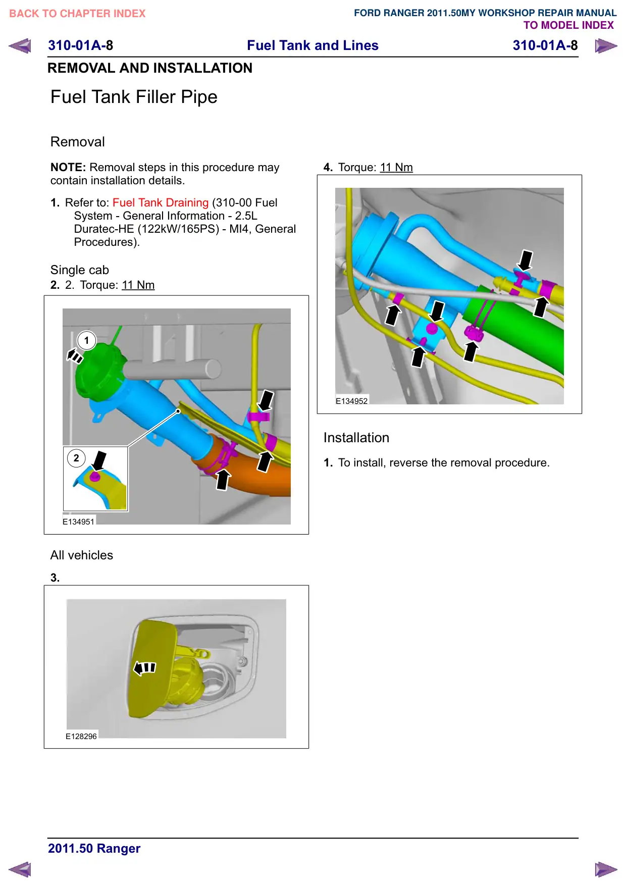
1. To install, reverse the removal procedure.
Fuel Tank and Lines
310-01A-
310-01A-
REMOVAL AND INSTALLATION
Fuel Filter
Removal
NOTE: Removal steps in this procedure may
contain installation details.
1. Refer to: Petrol and Petrol-Ethanol Fuel
Systems Health and Safety Precautions
(100-00 General Information, Description and
Operation).
2. Refer to: Lifting (100-02 Jacking and Lifting,
Description and Operation).
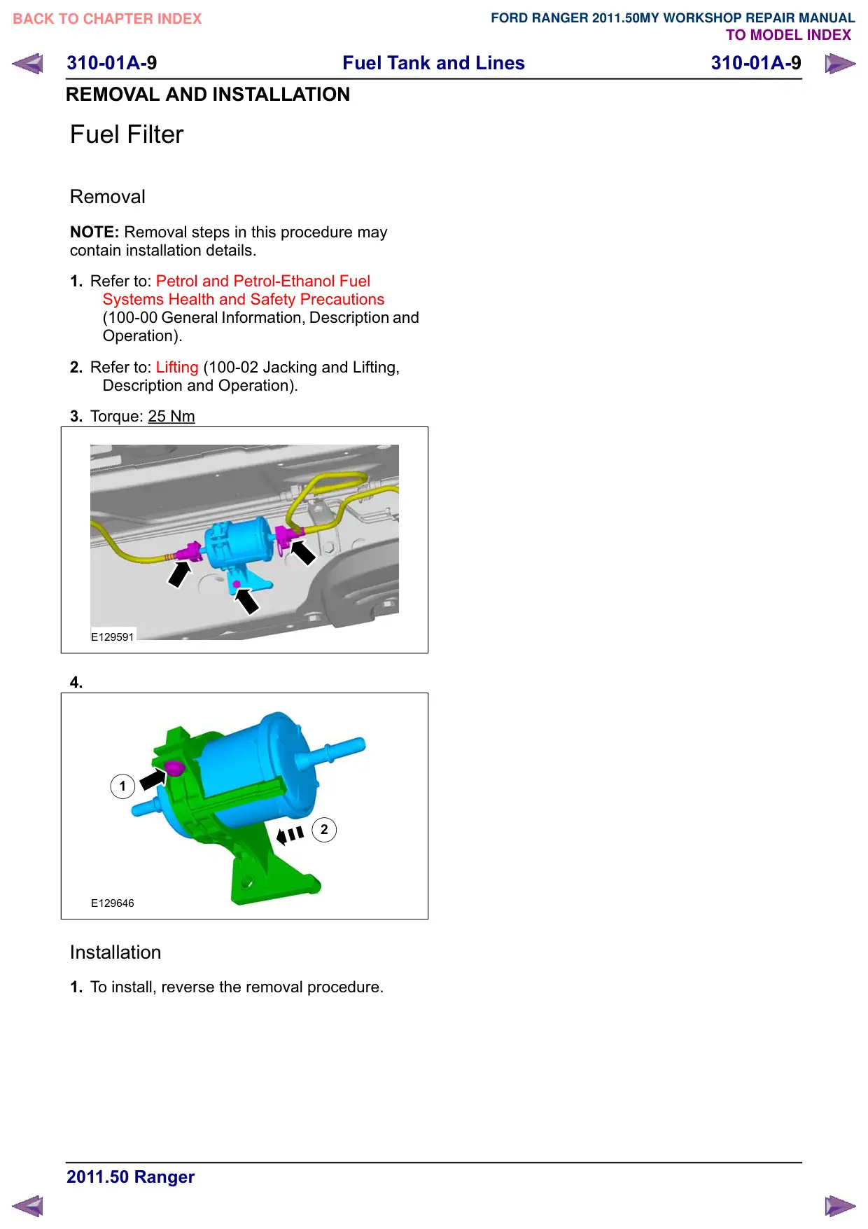
3. Torque: 25 Nm
E129591
4.
1
2
E129646
Installation
1. To install, reverse the removal procedure.
Fuel Tank and Lines
310-01A-10
310-01A-10
REMOVAL AND INSTALLATION
Fuel Pump and Sender Unit
Special Tool(s)
310-037
Remover/Installer, Fuel Tank
Sender Unit
23042
Removal
1. Refer to: Fuel Tank (310-01 Fuel Tank and
Lines, Removal and Installation).
2.
CAUTION: Take extra care not to
damage the fuel tank level sensor float
and arm.
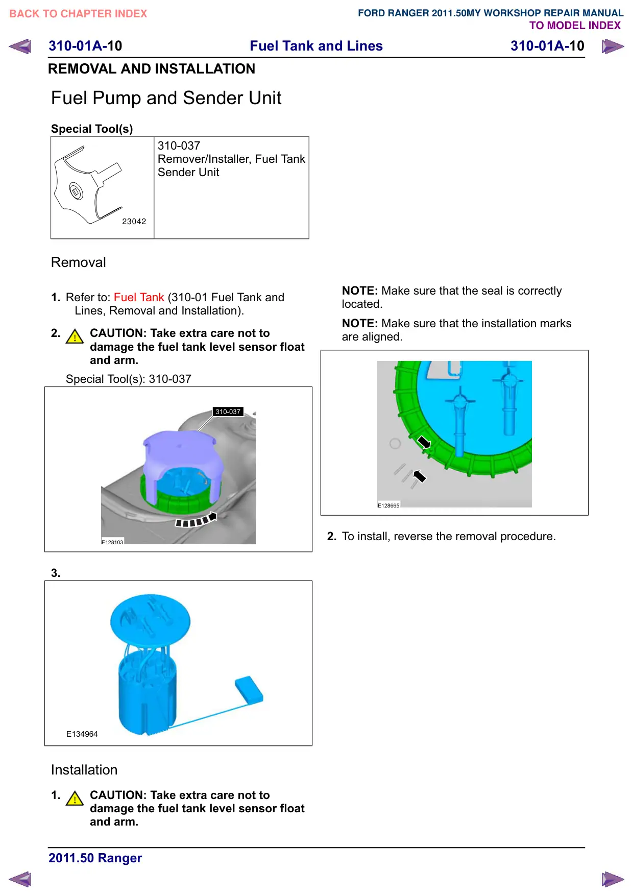
Special Tool(s): 310-037
310-037
E128103
3.
E134964
Installation
1.
CAUTION: Take extra care not to
damage the fuel tank level sensor float
and arm.
NOTE: Make sure that the seal is correctly
located.
NOTE: Make sure that the installation marks
are aligned.
E128665
2. To install, reverse the removal procedure.