211-03 Articulações da direção
Texto completo da seção, página por página. Toque no título para ver a página com a imagem.
- Índice da seção p. 240
- Barra de direção p. 241–243
- Terminal de direção p. 244
Página 240 · Índice da seção
Contents
https://ranger.mbrace.com.br/oficina/240 · imagem: https://ranger.mbrace.com.br/img/oficina/240.webp
Steering Linkage
211-03-1
211-03-1
.
SECTION 211-03 Steering Linkage
VEHICLE APPLICATION: 2011.50 Ranger
CONTENTS
REMOVAL AND INSTALLATION
Tie Rod...........................................................................................................
Tie Rod End....................................................................................................
PAGE
(13 263 0)
211-03-2
(13 273 0)
211-03-5
Página 241 · Barra de direção
Tie Rod
https://ranger.mbrace.com.br/oficina/241 · imagem: https://ranger.mbrace.com.br/img/oficina/241.webp
Steering Linkage
211-03-2
211-03-2
REMOVAL AND INSTALLATION
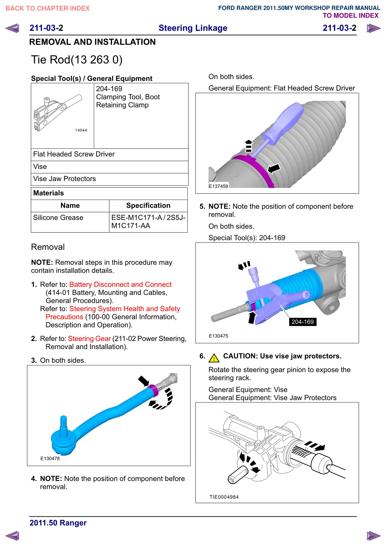
Tie Rod(13 263 0)
Special Tool(s) / General Equipment
204-169
Clamping Tool, Boot
Retaining Clamp
14044
Flat Headed Screw Driver
Vise
Vise Jaw Protectors
Materials
Name
Specification
Silicone Grease
ESE-M1C171-A / 2S5J-
M1C171-AA
Removal
NOTE: Removal steps in this procedure may
contain installation details.
1. Refer to: Battery Disconnect and Connect
(414-01 Battery, Mounting and Cables,
General Procedures).
Refer to: Steering System Health and Safety
Precautions (100-00 General Information,
Description and Operation).
2. Refer to: Steering Gear (211-02 Power Steering,
Removal and Installation).
3. On both sides.
E130478
4. NOTE: Note the position of component before
removal.
On both sides.
General Equipment: Flat Headed Screw Driver
E137459
5. NOTE: Note the position of component before
removal.
On both sides.
Special Tool(s): 204-169
204-169
E130475
6.
CAUTION: Use vise jaw protectors.
Rotate the steering gear pinion to expose the
steering rack.
General Equipment: Vise
General Equipment: Vise Jaw Protectors
TIE0004984
Página 242 · Barra de direção
Tie Rod
https://ranger.mbrace.com.br/oficina/242 · imagem: https://ranger.mbrace.com.br/img/oficina/242.webp
211-03-3
Steering Linkage
211-03-3
REMOVAL AND INSTALLATION
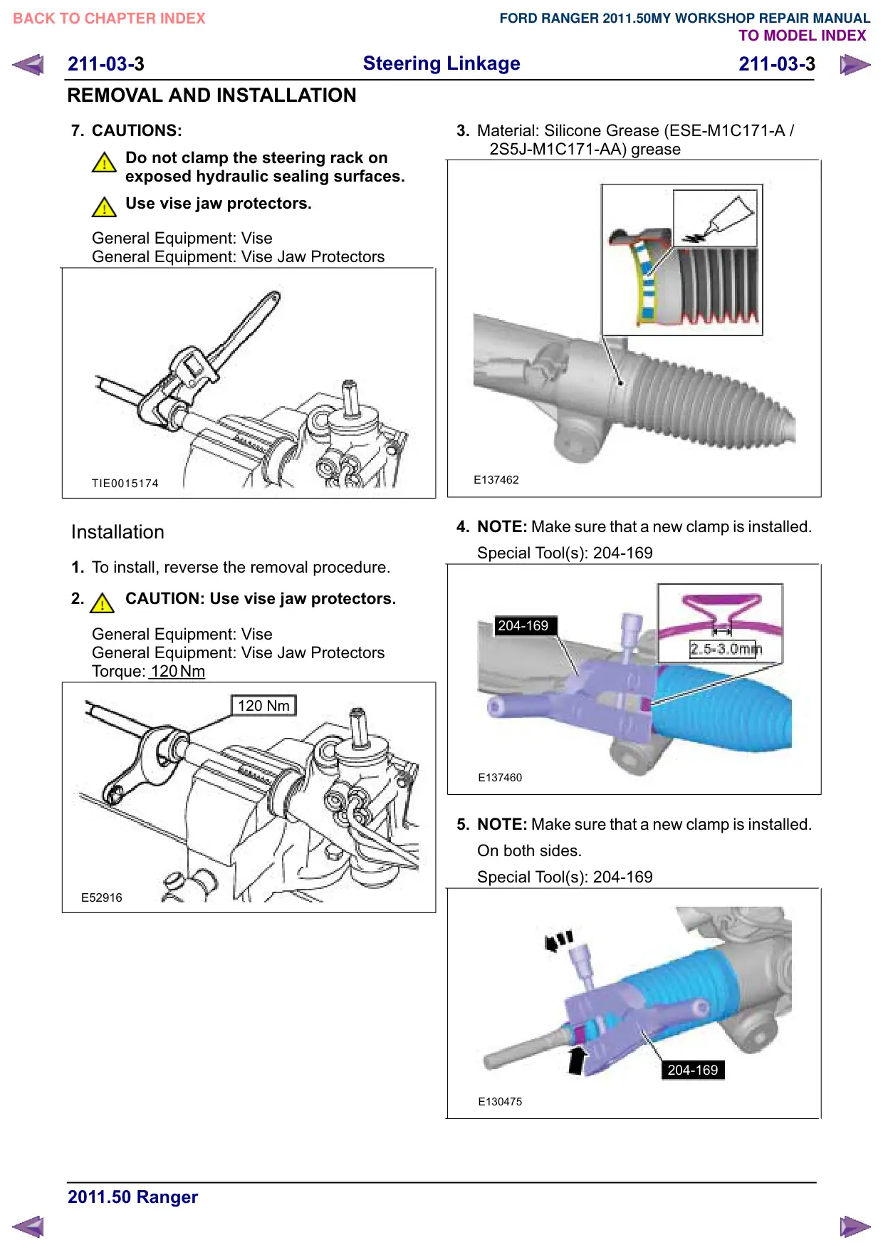
7. CAUTIONS:
Do not clamp the steering rack on
exposed hydraulic sealing surfaces.
Use vise jaw protectors.
General Equipment: Vise
General Equipment: Vise Jaw Protectors
TIE0015174
Installation
1. To install, reverse the removal procedure.
2.
CAUTION: Use vise jaw protectors.
General Equipment: Vise
General Equipment: Vise Jaw Protectors
Torque: 120
Nm
120 Nm
E52916
3. Material: Silicone Grease (ESE-M1C171-A /
2S5J-M1C171-AA) grease
E137462
4. NOTE: Make sure that a new clamp is installed.
Special Tool(s): 204-169
204-169
E137460
5. NOTE: Make sure that a new clamp is installed.
On both sides.
Special Tool(s): 204-169
204-169
E130475
Página 243 · Barra de direção
Tie Rod
https://ranger.mbrace.com.br/oficina/243 · imagem: https://ranger.mbrace.com.br/img/oficina/243.webp
Steering Linkage
211-03-4
211-03-4
REMOVAL AND INSTALLATION
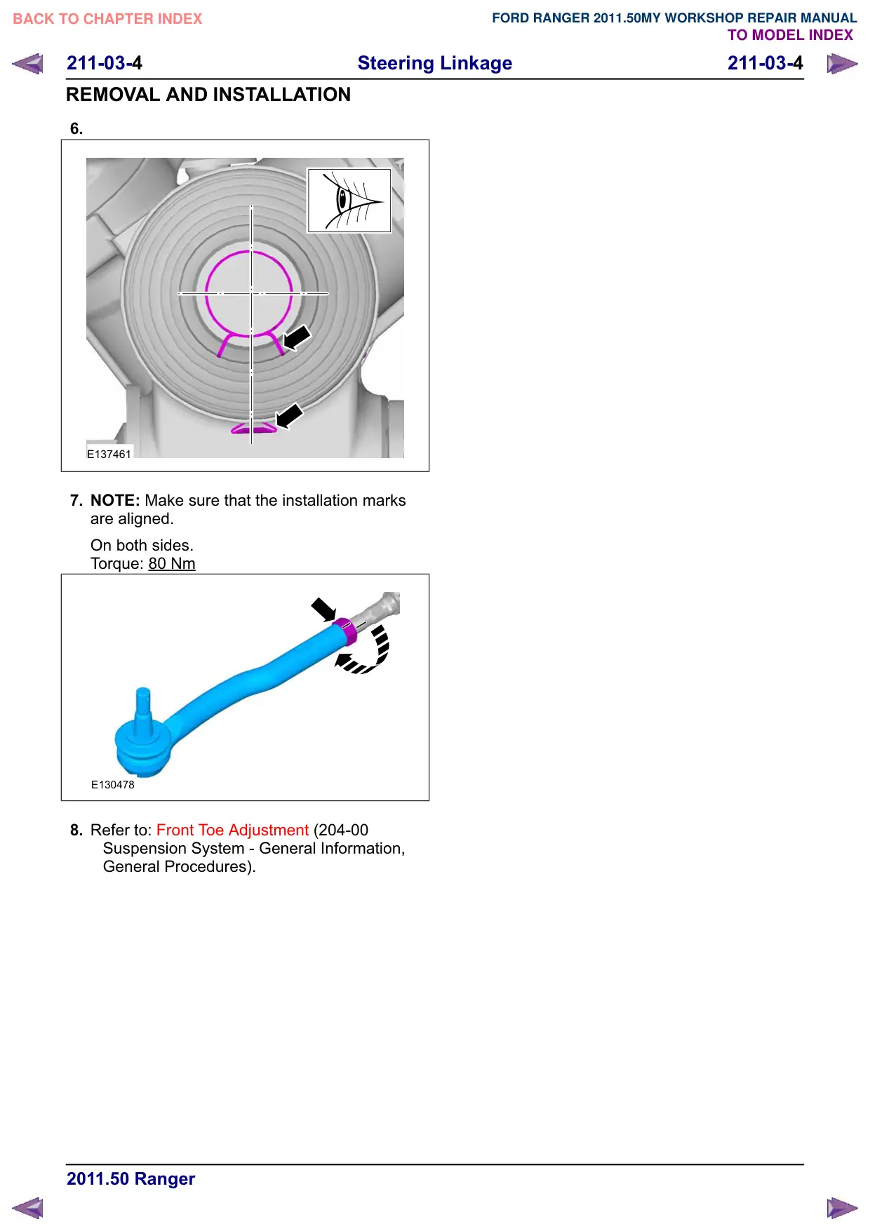
6.
E137461
7. NOTE: Make sure that the installation marks
are aligned.
On both sides.
Torque: 80 Nm
E130478
8. Refer to: Front Toe Adjustment (204-00
Suspension System - General Information,
General Procedures).
Página 244 · Terminal de direção
Tie Rod End
https://ranger.mbrace.com.br/oficina/244 · imagem: https://ranger.mbrace.com.br/img/oficina/244.webp
Steering Linkage
211-03-5
211-03-5
REMOVAL AND INSTALLATION
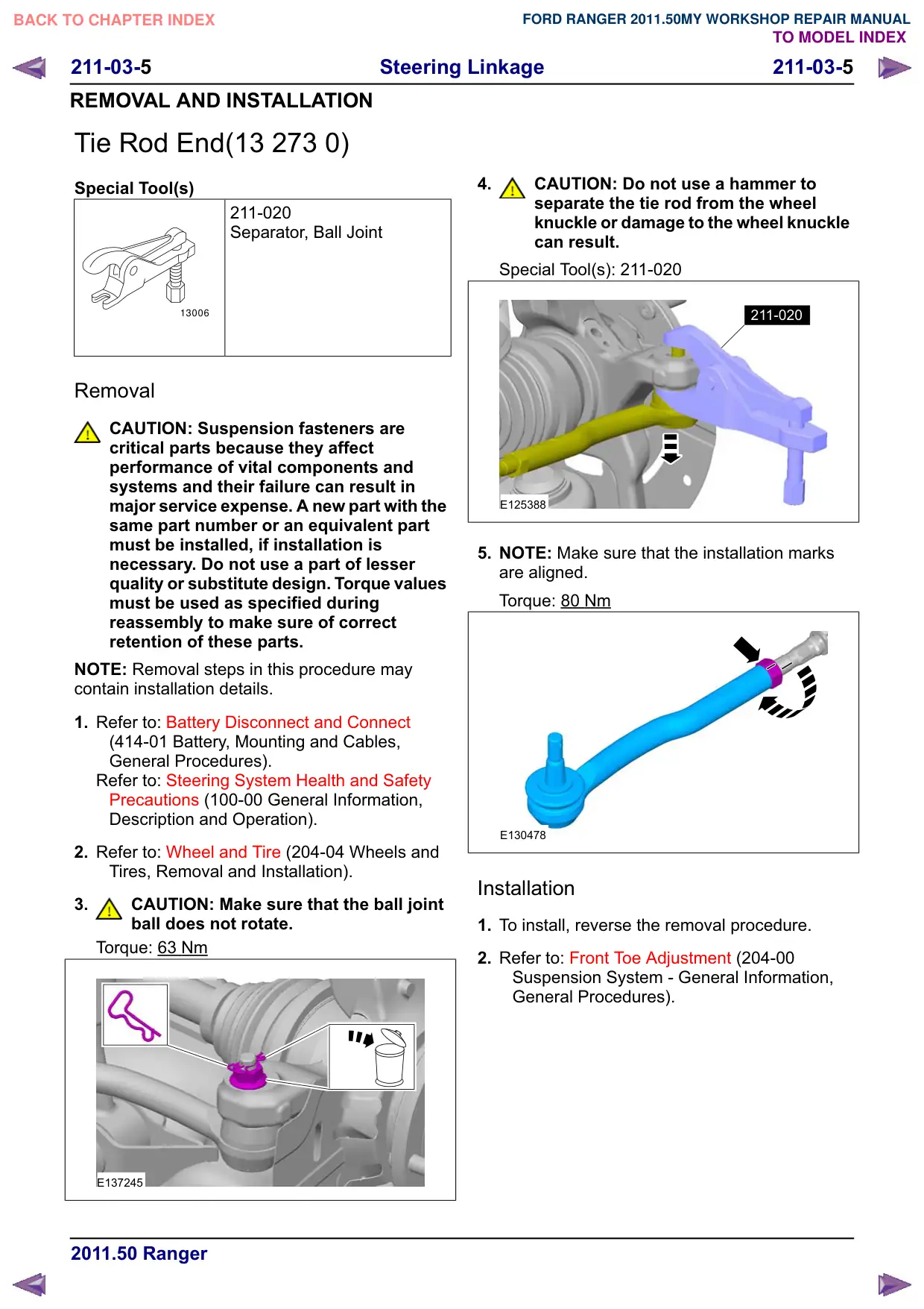
Tie Rod End(13 273 0)
Special Tool(s)
211-020
Separator, Ball Joint
13006
Removal
CAUTION: Suspension fasteners are
critical parts because they affect
performance of vital components and
systems and their failure can result in
major service expense. A new part with the
same part number or an equivalent part
must be installed, if installation is
necessary. Do not use a part of lesser
quality or substitute design. Torque values
must be used as specified during
reassembly to make sure of correct
retention of these parts.
NOTE: Removal steps in this procedure may
contain installation details.
1. Refer to: Battery Disconnect and Connect
(414-01 Battery, Mounting and Cables,
General Procedures).
Refer to: Steering System Health and Safety
Precautions (100-00 General Information,
Description and Operation).
2. Refer to: Wheel and Tire (204-04 Wheels and
Tires, Removal and Installation).
3.
CAUTION: Make sure that the ball joint
ball does not rotate.
Torque: 63 Nm
E137245
4.
CAUTION: Do not use a hammer to
separate the tie rod from the wheel
knuckle or damage to the wheel knuckle
can result.
Special Tool(s): 211-020
211-020
E125388
5. NOTE: Make sure that the installation marks
are aligned.
Torque: 80 Nm
E130478
Installation
1. To install, reverse the removal procedure.
2. Refer to: Front Toe Adjustment (204-00
Suspension System - General Information,
General Procedures).