204-00 Suspensão – informações gerais e alinhamento
Texto completo da seção, página por página. Toque no título para ver a página com a imagem.
- Informações p. 93
- Ajuste de cambagem e cáster p. 94
- Ajuste da convergência dianteira p. 95
Página 93 · Informações
Information
https://ranger.mbrace.com.br/oficina/93 · imagem: https://ranger.mbrace.com.br/img/oficina/93.webp
Suspension System - General Information
204-00-1
204-00-1
.
SECTION 204-00 Suspension System - General
Information
VEHICLE APPLICATION: 2011.50 Ranger
CONTENTS
GENERAL PROCEDURES
Camber and Caster Adjustment.........................................................................................
Front Toe Adjustment.....................................................................................
PAGE
204-00-2
(14 117 3)
204-00-3
Página 94 · Ajuste de cambagem e cáster
Camber and Caster Adjustment
https://ranger.mbrace.com.br/oficina/94 · imagem: https://ranger.mbrace.com.br/img/oficina/94.webp
Suspension System - General Information
204-00-2
204-00-2
GENERAL PROCEDURES
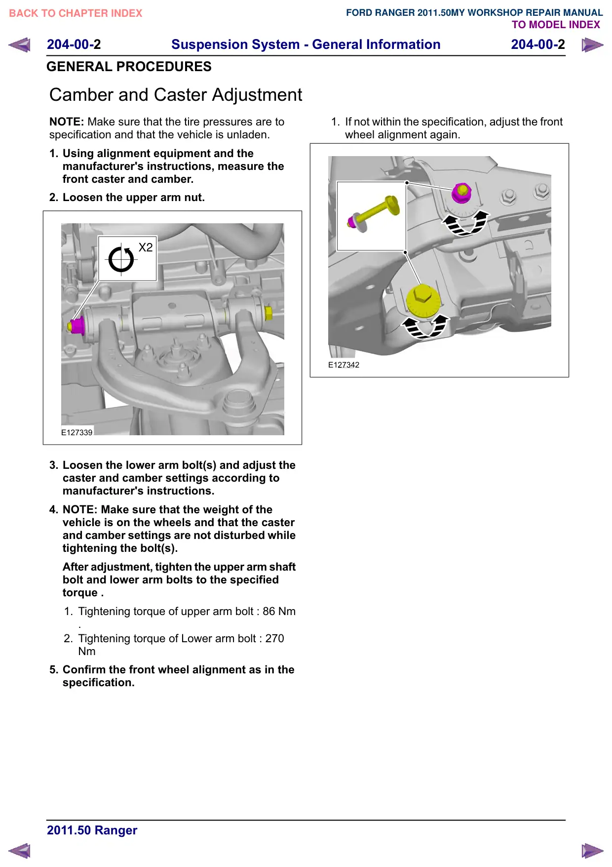
Camber and Caster Adjustment
NOTE: Make sure that the tire pressures are to
specification and that the vehicle is unladen.
1. Using alignment equipment and the
manufacturer's instructions, measure the
front caster and camber.
2. Loosen the upper arm nut.
X2
E127339
3. Loosen the lower arm bolt(s) and adjust the
caster and camber settings according to
manufacturer's instructions.
4. NOTE: Make sure that the weight of the
vehicle is on the wheels and that the caster
and camber settings are not disturbed while
tightening the bolt(s).
After adjustment, tighten the upper arm shaft
bolt and lower arm bolts to the specified
torque .
1. Tightening torque of upper arm bolt : 86 Nm
.
2. Tightening torque of Lower arm bolt : 270
Nm
5. Confirm the front wheel alignment as in the
specification.
1. If not within the specification, adjust the front
wheel alignment again.
E127342
Página 95 · Ajuste da convergência dianteira
Front Toe Adjustment
https://ranger.mbrace.com.br/oficina/95 · imagem: https://ranger.mbrace.com.br/img/oficina/95.webp
Suspension System - General Information
204-00-3
204-00-3
GENERAL PROCEDURES
Front Toe Adjustment(14 117 3)
General Equipment
Wheel alignment system
NOTE: Make sure that the vehicle is standing on
a level surface.
NOTE: Make sure that the tire pressures are to
specification and that the vehicle is unladen.
1.
E125822
CAUTION: Make sure that the steering
wheel lock is engaged.
NOTE: Make sure that the road wheels are in the
straight ahead position.
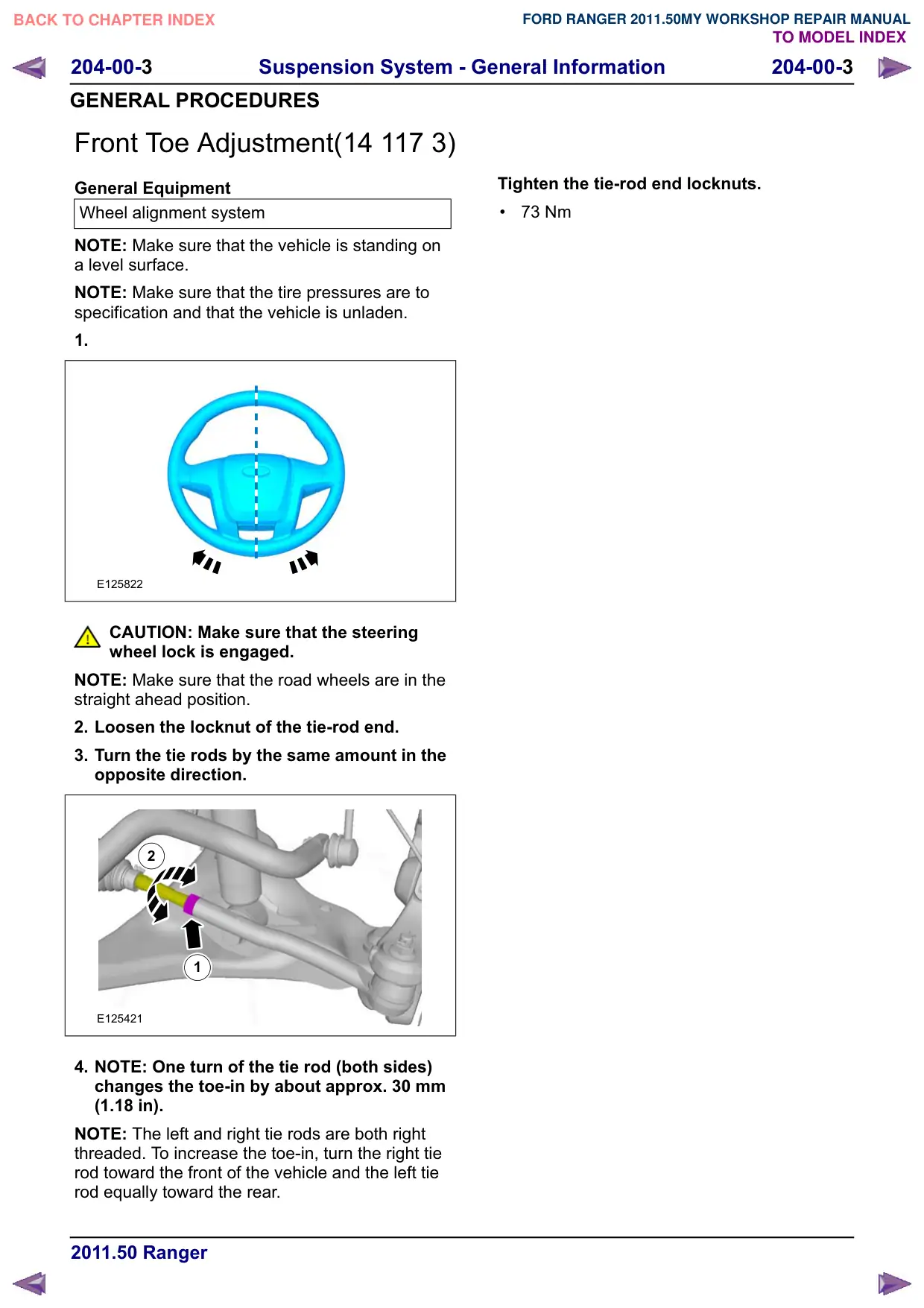
2. Loosen the locknut of the tie-rod end.
3. Turn the tie rods by the same amount in the
opposite direction.
2
1
E125421
4. NOTE: One turn of the tie rod (both sides)
changes the toe-in by about approx. 30 mm
(1.18 in).
NOTE: The left and right tie rods are both right
threaded. To increase the toe-in, turn the right tie
rod toward the front of the vehicle and the left tie
rod equally toward the rear.
Tighten the tie-rod end locknuts.
73 Nm