4 Elétrica
Texto completo da seção, página por página. Toque no título para ver a página com a imagem.
- 4.1.1 Informações da bateria p. 22
- 4.1.2 Gerador e alternador p. 23
- 4.2.2 Lâmpadas externas adicionais p. 24
Página 22 · 4.1.1 Informações da bateria
4.1.1 Battery Information
https://ranger.mbrace.com.br/implementos/22 · imagem: https://ranger.mbrace.com.br/img/implementos/22.webp
4 Electrical
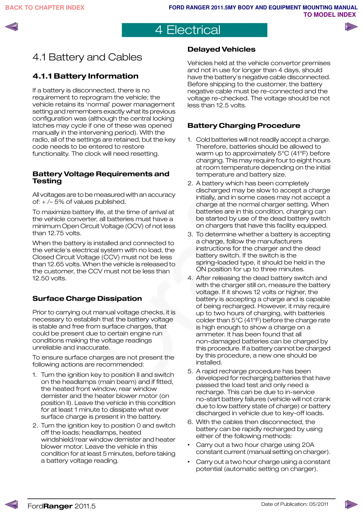
4.1 Battery and Cables
4.1.1 Battery Information
If a battery is disconnected, there is no
requirement to reprogram the vehicle; the
vehicle retains its ‘normal’ power management
setting and remembers exactly what its previous
configuration was (although the central locking
latches may cycle if one of these was opened
manually in the intervening period). With the
radio, all of the settings are retained, but the key
code needs to be entered to restore
functionality. The clock will need resetting.
Battery Voltage Requirements and
Testing
All voltages are to be measured with an accuracy
of: + /– 5% of values published.
To maximize battery life, at the time of arrival at
the vehicle converter, all batteries must have a
minimum Open Circuit Voltage (OCV) of not less
than 12.75 volts.
When the battery is installed and connected to
the vehicle's electrical system with no load, the
Closed Circuit Voltage (CCV) must not be less
than 12.65 volts. When the vehicle is released to
the customer, the CCV must not be less than
12.50 volts.
Surface Charge Dissipation
Prior to carrying out manual voltage checks, it is
necessary to establish that the battery voltage
is stable and free from surface charges, that
could be present due to certain engine run
conditions making the voltage readings
unreliable and inaccurate.
To ensure surface charges are not present the
following actions are recommended:
1. Turn the ignition key to position II and switch
on the headlamps (main beam) and if fitted,
the heated front window, rear window
demister and the heater blower motor (on
position II). Leave the vehicle in this condition
for at least 1 minute to dissipate what ever
surface charge is present in the battery.
2. Turn the ignition key to position 0 and switch
off the loads; headlamps, heated
windshield/rear window demister and heater
blower motor. Leave the vehicle in this
condition for at least 5 minutes, before taking
a battery voltage reading.
FordRanger 2011.5
Delayed Vehicles
Vehicles held at the vehicle convertor premises
and not in use for longer than 4 days, should
have the battery's negative cable disconnected.
Before shipping to the customer, the battery
negative cable must be re-connected and the
voltage re-checked. The voltage should be not
less than 12.5 volts.
Battery Charging Procedure
1. Cold batteries will not readily accept a charge.
Therefore, batteries should be allowed to
warm up to approximately 5°C (41°F) before
charging. This may require four to eight hours
at room temperature depending on the initial
temperature and battery size.
2. A battery which has been completely
discharged may be slow to accept a charge
initially, and in some cases may not accept a
charge at the normal charger setting. When
batteries are in this condition, charging can
be started by use of the dead battery switch
on chargers that have this facility equipped.
3. To determine whether a battery is accepting
a charge, follow the manufacturers
instructions for the charger and the dead
battery switch. If the switch is the
spring-loaded type, it should be held in the
ON position for up to three minutes.
4. After releasing the dead battery switch and
with the charger still on, measure the battery
voltage. If it shows 12 volts or higher, the
battery is accepting a charge and is capable
of being recharged. However, it may require
up to two hours of charging, with batteries
colder than 5°C (41°F) before the charge rate
is high enough to show a charge on a
ammeter. It has been found that all
non-damaged batteries can be charged by
this procedure. If a battery cannot be charged
by this procedure, a new one should be
installed.
5. A rapid recharge procedure has been
developed for recharging batteries that have
passed the load test and only need a
recharge. This can be due to in-service
no-start battery failures (vehicle will not crank
due to low battery state of charge) or battery
discharged in vehicle due to key-off loads.
6. With the cables then disconnected, the
battery can be rapidly recharged by using
either of the following methods:
•
Carry out a two hour charge using 20A
constant current (manual setting on charger).
•
Carry out a two hour charge using a constant
potential (automatic setting on charger).
Date of Publication: 05/2011
Página 23 · 4.1.2 Gerador e alternador
4.1.2 Generator and Alternator
https://ranger.mbrace.com.br/implementos/23 · imagem: https://ranger.mbrace.com.br/img/implementos/23.webp
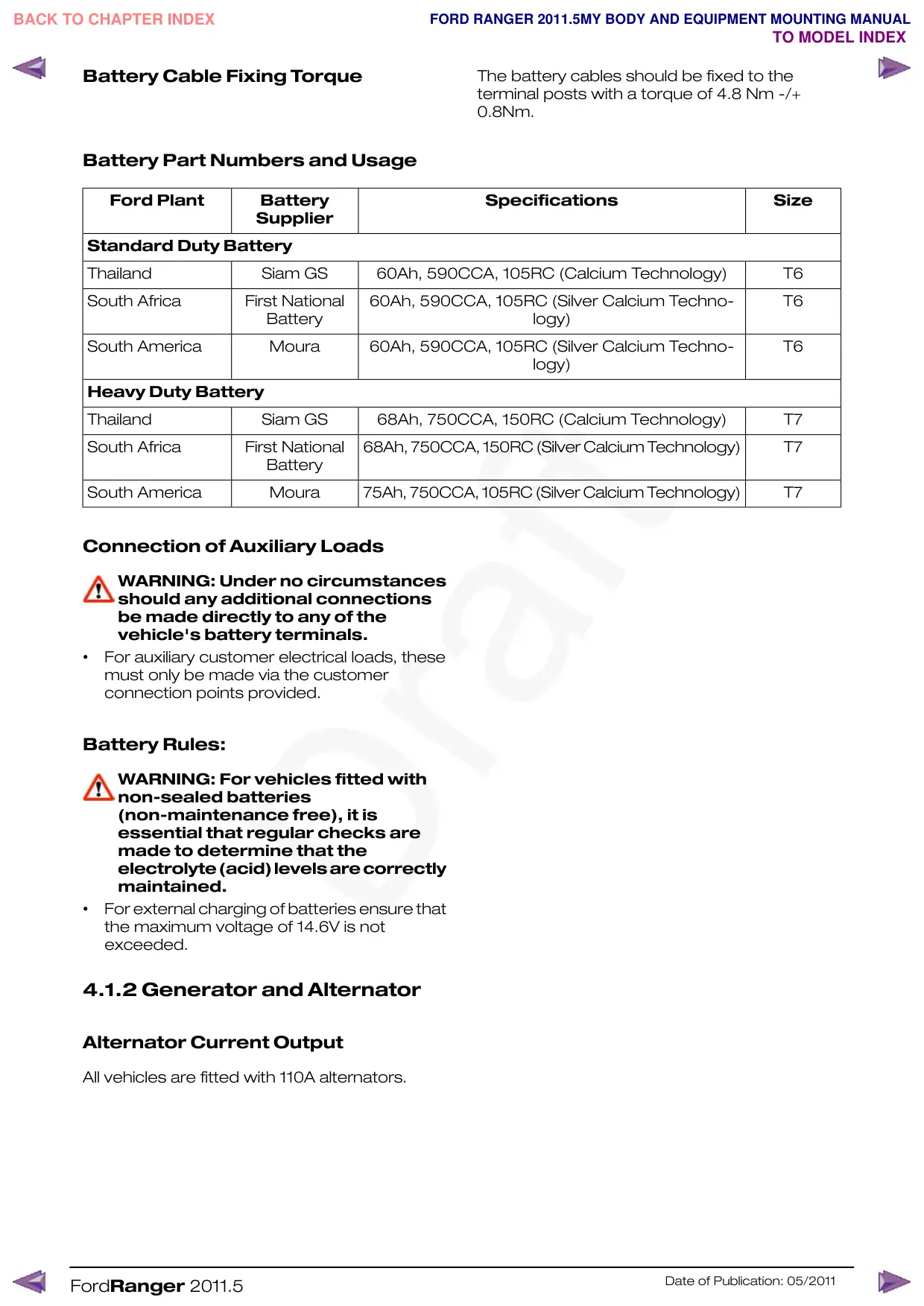
Battery Cable Fixing Torque
The battery cables should be fixed to the
terminal posts with a torque of 4.8 Nm -/+
0.8Nm.
Battery Part Numbers and Usage
Ford Plant
Battery
Supplier
Standard Duty Battery
Thailand
Siam GS
60Ah, 590CCA, 105RC (Calcium Technology)
South Africa
First National
60Ah, 590CCA, 105RC (Silver Calcium Techno-
Battery
South America
Moura
60Ah, 590CCA, 105RC (Silver Calcium Techno-
Heavy Duty Battery
Thailand
Siam GS
68Ah, 750CCA, 150RC (Calcium Technology)
South Africa
First National
68Ah, 750CCA, 150RC (Silver Calcium Technology)
Battery
South America
Moura
75Ah, 750CCA, 105RC (Silver Calcium Technology)
Connection of Auxiliary Loads
WARNING: Under no circumstances
should any additional connections
be made directly to any of the
vehicle's battery terminals.
•
For auxiliary customer electrical loads, these
must only be made via the customer
connection points provided.
Battery Rules:
WARNING: For vehicles fitted with
non-sealed batteries
(non-maintenance free), it is
essential that regular checks are
made to determine that the
electrolyte(acid)levelsarecorrectly
maintained.
•
For external charging of batteries ensure that
the maximum voltage of 14.6V is not
exceeded.
4.1.2 Generator and Alternator
Alternator Current Output
All vehicles are fitted with 110A alternators.
FordRanger 2011.5
Specifications
Size
T6
T6
logy)
T6
logy)
T7
T7
T7
Date of Publication: 05/2011
Página 24 · 4.2.2 Lâmpadas externas adicionais
4.2.2 Additional External Lamps
https://ranger.mbrace.com.br/implementos/24 · imagem: https://ranger.mbrace.com.br/img/implementos/24.webp
4.2 Exterior Lighting
WARNING: Make sure that the
modified vehicle complies with all
relevant legal requirements.
4.2.1 Reversing Lamps
The reverse lamps are activated by the reverse
switch on the transmission and passing through
the Central Junction Box where the signal is
sensed. A marginal increase in current (via a relay
or buffered electrical input) is permissible to
trigger a rear-view camera system, or audible
device.
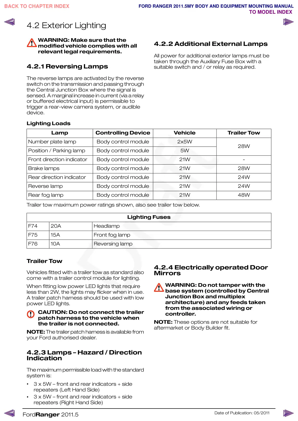
Lighting Loads
Lamp
Controlling Device
Number plate lamp
Body control module
Position / Parking lamp
Body control module
Front direction indicator
Body control module
Brake lamps
Body control module
Rear direction indicator
Body control module
Reverse lamp
Body control module
Rear fog lamp
Body control module
Trailer tow maximum power ratings shown, also see trailer tow below.
Lighting Fuses
F74
20A
Headlamp
F75
15A
Front fog lamp
F76
10A
Reversing lamp
Trailer Tow
Vehicles fitted with a trailer tow as standard also
come with a trailer control module for lighting.
When fitting low power LED lights that require
less than 2W, the lights may flicker when in use.
A trailer patch harness should be used with low
power LED lights.
CAUTION: Do not connect the trailer
patch harness to the vehicle when
the trailer is not connected.
NOTE:The trailer patch harness is available from
your Ford authorised dealer.
4.2.3 Lamps – Hazard / Direction
Indication
The maximum permissible load with the standard
system is:
•
3 x 5W – front and rear indicators + side
repeaters (Left Hand Side)
•
3 x 5W – front and rear indicators + side
repeaters (Right Hand Side)
FordRanger 2011.5
4.2.2 Additional External Lamps
All power for additional exterior lamps must be
taken through the Auxiliary Fuse Box with a
suitable switch and / or relay as required.
Vehicle
Trailer Tow
2x5W
28W
5W
21W
-
21W
28W
21W
24W
21W
24W
21W
48W
4.2.4 Electrically operated Door
Mirrors
WARNING: Do not tamper with the
base system (controlled by Central
Junction Box and multiplex
architecture) and any feeds taken
from the associated wiring or
controller.
NOTE: These options are not suitable for
aftermarket or Body Builder fit.
Date of Publication: 05/2011