Fuel Charging and Controls–3.2LDuratorq-TDCi(148kW/200PS)
303-04C-2
303-04C-2
- Puma
DESCRIPTION AND OPERATION
Fuel Charging and Controls
Overview
1
6
4
5
3
E129822
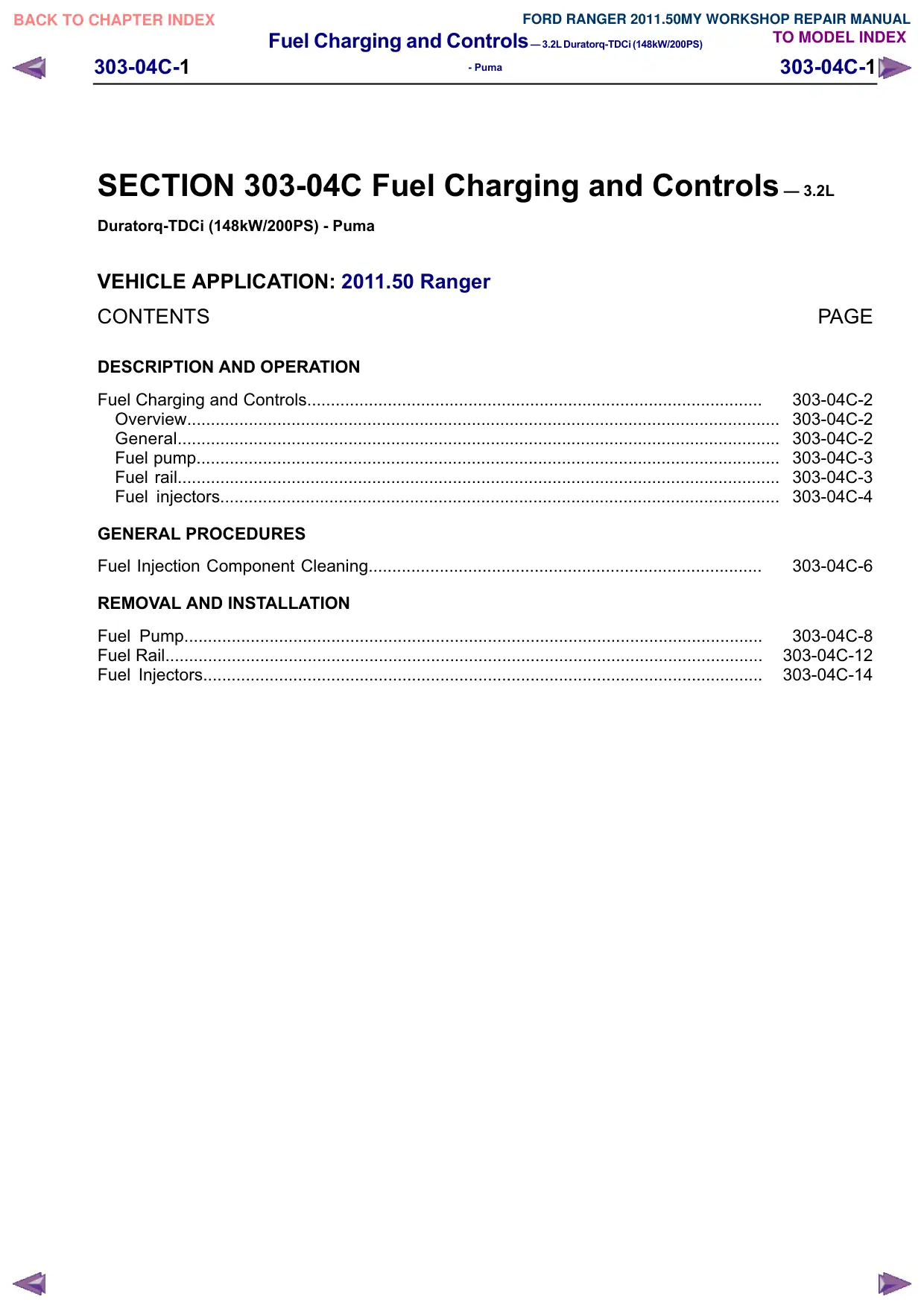
Item
Description
1
Fuel rail
2
Fuel injector(s)
3
Fuel pressure (FRP) sensor
4
Fuel metering valve
5
Fuel temperature sensor
6
Fuel pump
General
A common rail fuel injection system is used on the
3.2L Duratorq-TDCi (Puma) diesel engine.
Within the fuel pump there is an integral fuel
transfer pump which draws the fuel from the fuel
tank to the fuel pump.
A fuel metering valve is located in the supply port
to the high-pressure chamber of the fuel pump.
The fuel metering valve varies the quantity of fuel
2
supplied to the fuel rail and fuel injector(s), in
relation to the driving conditions.
The fuel is supplied at high-pressure to the fuel rail
and to the fuel injectors ready for injection.
Depending on engine operating conditions, the fuel
injection pressure varies between 230 bar and
1600 bar.
Fuel system pressure is measured using an FRP
sensor located in the fuel rail. The FRP sensor
converts the fuel system pressure into a voltage
signal. This voltage signal acts as an input signal
to the powertrain control module (PCM) for
calculation of the fuel injection quantity.
The power train control module (PCM) calculates
the time of fuel injection and the fuel injection
quantity depending on various input variables. The
specified quantity of fuel is injected into the
respective combustion chamber through the
solenoid actuated fuel injector(s). In doing so, a
pre-injection and a main injection occur each time.
The excess fuel is returned to the fuel tank through
the fuel return line.
Fuel Charging and Controls–3.2LDuratorq-TDCi(148kW/200PS)
303-04C-3
303-04C-3
- Puma
DESCRIPTION AND OPERATION
Fuel pump
3
1
2
7
E129442
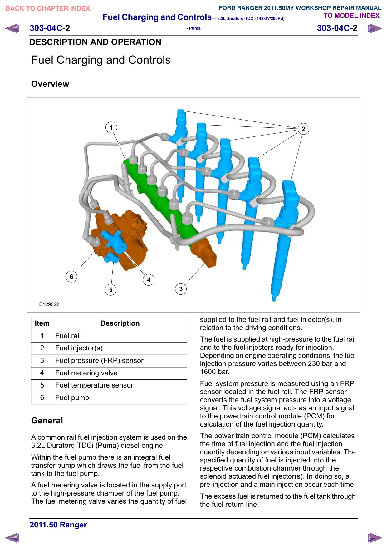
Item
Description
1
Fuel pump high-pressure outlet union
2
Fuel pump fuel return union
3
Fuel metering valve
4
Fuel temperature sensor
5
Fuel pump O-ring seal
6
Fuel pump input drive
7
Fuel pump fuel supply union
Fuel rail
1
2
3
E129823
5
4
6
The fuel pump is driven directly by the timing belt.
The fuel pump has three pump elements, each
offset from each other by 120 degrees.
The fuel transfer pump is incorporated into the fuel
pump and is located on the drive flange. The fuel
transfer pump is a cycloid type pump.
The fuel metering valve is actuated by the PCM
using pulse width modulation.
4
5
6
7
8
Fuel Charging and Controls–3.2LDuratorq-TDCi(148kW/200PS)
303-04C-4
303-04C-4
- Puma
DESCRIPTION AND OPERATION
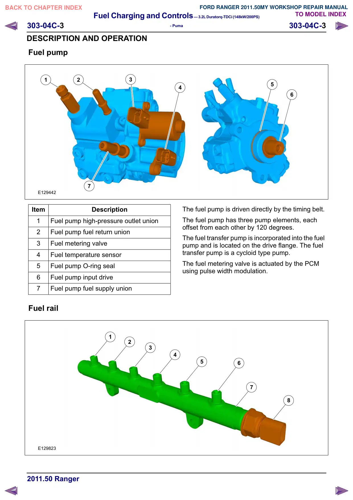
Item
Description
1
Fuel rail to fuel injector number 1
high-pressure fuel supply line union
2
Fuel rail to fuel injector number 2
high-pressure fuel supply line union
3
Fuel rail to fuel injector number 3
high-pressure fuel supply line union
4
Fuel pump to fuel rail high-pressure fuel
supply line union
5
Fuel rail to fuel injector number 4
high-pressure fuel supply line union
6
Fuel rail to fuel injector number 5
high-pressure fuel supply line union
7
Fuel rail
8
FRP sensor
CAUTION: The FRP sensor must not be
detached or removed from the fuel rail.
The fuel rail is made from forged steel and is
retained by a support bracket located on the
camshaft carrier.
The fuel is delivered by one high-pressure fuel
supply line from the fuel pump to the fuel rail.
From the fuel rail, the fuel travels through the
high-pressure fuel supply line(s) to the fuel
injector(s).
Fuel injectors
1
6
2
3
5
4
E129444
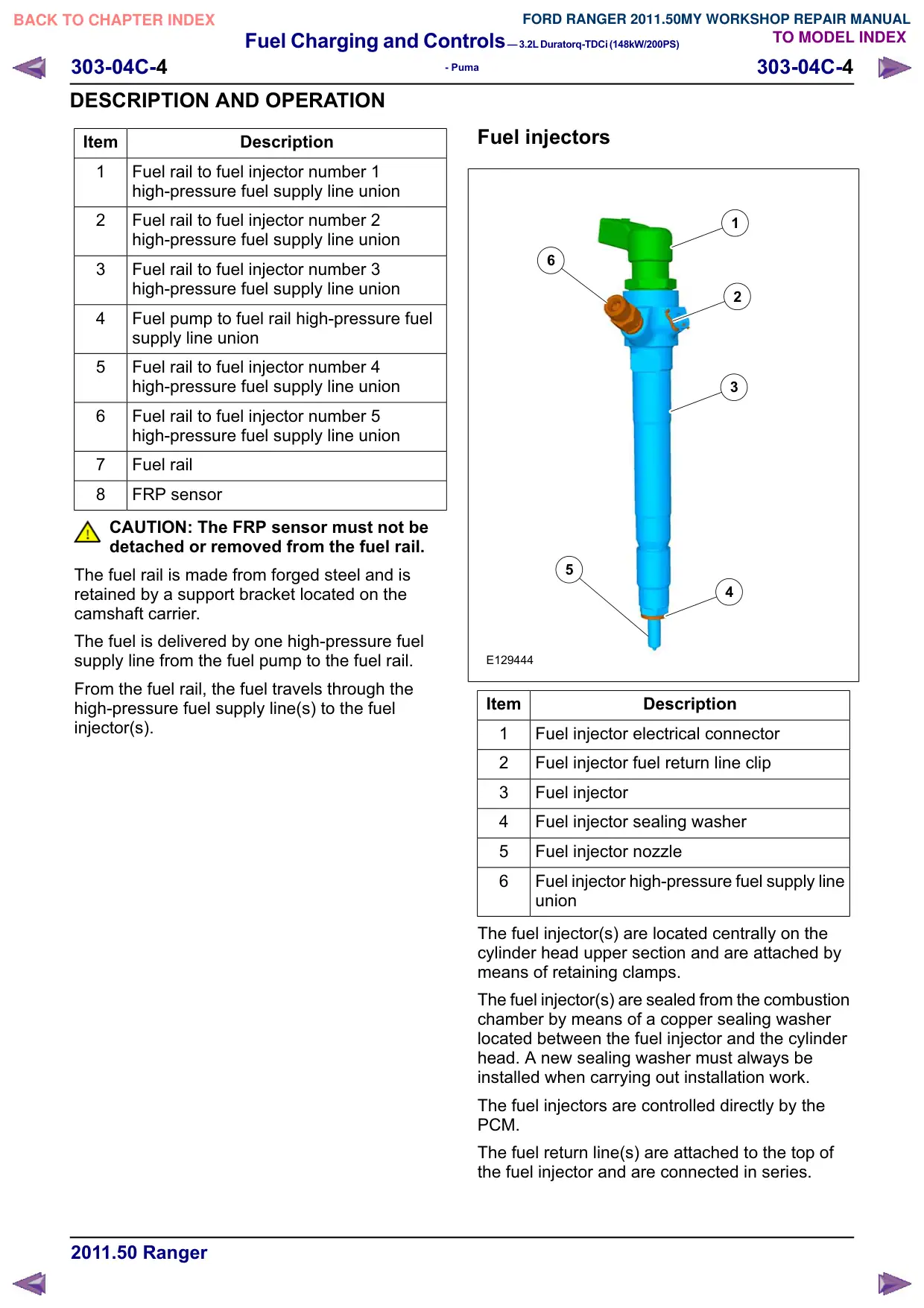
Item
Description
1
Fuel injector electrical connector
2
Fuel injector fuel return line clip
3
Fuel injector
4
Fuel injector sealing washer
5
Fuel injector nozzle
6
Fuel injector high-pressure fuel supply line
union
The fuel injector(s) are located centrally on the
cylinder head upper section and are attached by
means of retaining clamps.
The fuel injector(s) are sealed from the combustion
chamber by means of a copper sealing washer
located between the fuel injector and the cylinder
head. A new sealing washer must always be
installed when carrying out installation work.
The fuel injectors are controlled directly by the
PCM.
The fuel return line(s) are attached to the top of
the fuel injector and are connected in series.
Fuel Charging and Controls–3.2LDuratorq-TDCi(148kW/200PS)
303-04C-5
303-04C-5
- Puma
DESCRIPTION AND OPERATION
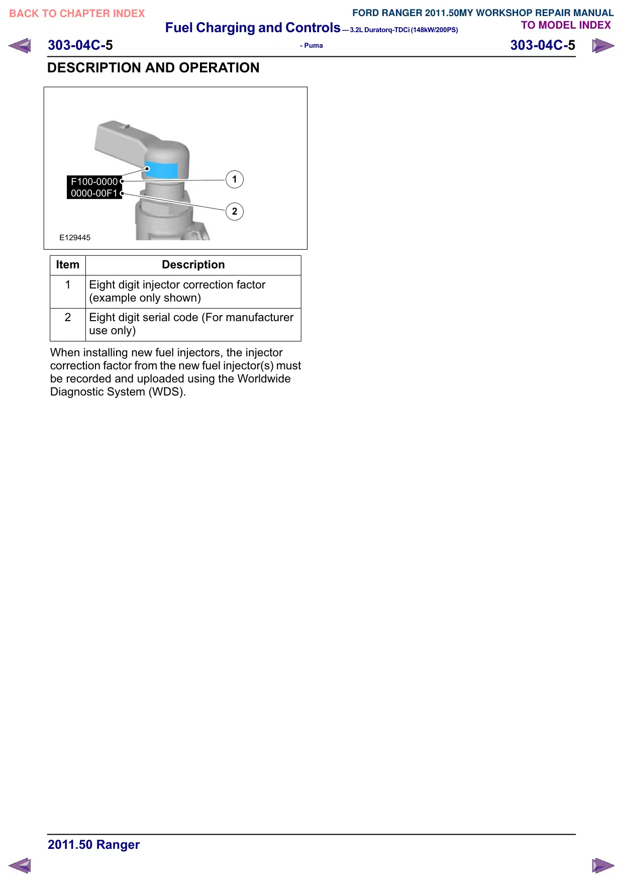
F100-0000
1
0000-00F1
2
E129445
Item
Description
1
Eight digit injector correction factor
(example only shown)
2
Eight digit serial code (For manufacturer
use only)
When installing new fuel injectors, the injector
correction factor from the new fuel injector(s) must
be recorded and uploaded using the Worldwide
Diagnostic System (WDS).
Fuel Charging and Controls–3.2LDuratorq-TDCi(148kW/200PS)
303-04C-6
303-04C-6
- Puma
GENERAL PROCEDURES
Fuel Injection Component Cleaning
General Equipment
Pneumatic vacuum gun
WARNINGS:
Do not smoke or carry lighted tobacco or
open flame of any type when working on
or near any fuel related components.
Highly flammable mixtures are always
present and may ignite. Failure to follow
these instructions may result in personal
injury.
Do not carry out any repairs to the fuel
injection system with the engine running.
The fuel pressure within the system can
be as high as 1600 bar. Failure to follow
this instruction may result in personal
injury.
Eye protection must be worn at all times
when working on or near any fuel related
components. Failure to follow this
instruction may result in personal injury.
CAUTIONS:
Make sure that the workshop area in which
the vehicle is being worked on is as clean
and dust-free as possible. Areas in which
work on clutches, brakes or where welding
or machining are carried out are not
suitable in view of the risk of
contamination to the fuel system.
Make sure that clean non-plated tools are
used. Clean tools using a new brush that
will not lose its bristles and fresh suitable
evaporative cleaning agent, prior to
starting work on the vehicle.
Use a steel topped workbench and cover
it with clean, lint-free non-flocking material.
Make sure that all parts removed from the
vehicle are placed on the lint-free
non-flocking material.
Make sure that any protective clothing
worn is clean and made from lint-free
non-flocking material.
Make sure that any protective gloves worn
are new and are of the non-powdered latex
type.
Before using the suitable evaporative
cleaning agent, protect all electrical
components and connectors with lint-free
non-flocking material.
1. For additional information, refer to: Solvents,
Sealants and Adhesives (100-00 General
Information, Description and Operation)
/ Diesel Fuel System Health and Safety
Precautions (100-00 General Information,
Description and Operation).
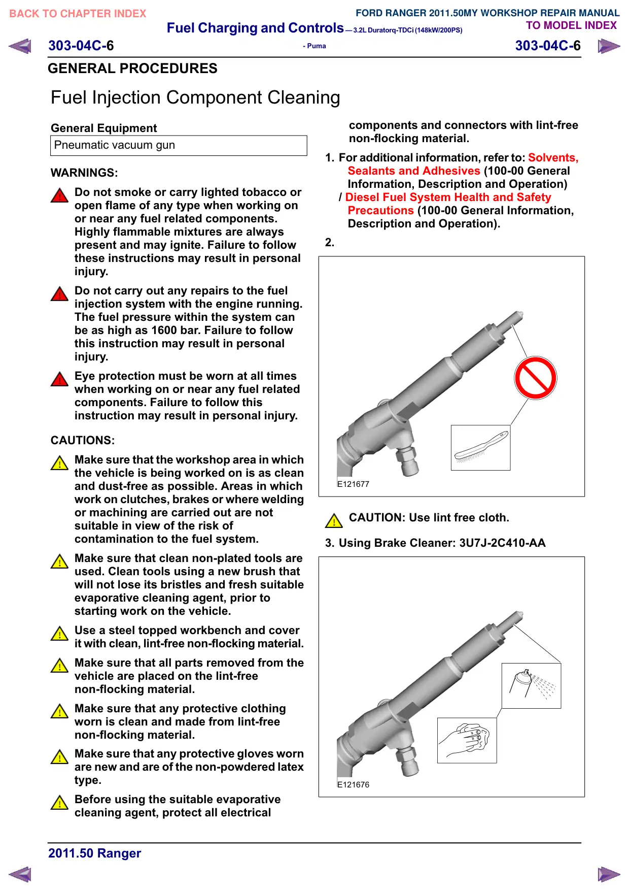
2.
E121677
CAUTION: Use lint free cloth.
3. Using Brake Cleaner: 3U7J-2C410-AA
E121676
Fuel Charging and Controls–3.2LDuratorq-TDCi(148kW/200PS)
303-04C-7
303-04C-7
- Puma
GENERAL PROCEDURES
4. Using a new brush that will not lose its
bristles, brush a suitable evaporative
cleaning agent onto the components being
removed and onto the surrounding area.
5. Using the pneumatic vacuum gun, remove
all traces of evaporative cleaning agent and
foreign material.
6. Dispose of any unused evaporative cleaning
agent and the brush after completing the
repair.
Fuel Charging and Controls–3.2LDuratorq-TDCi(148kW/200PS)
303-04C-8
303-04C-8
- Puma
REMOVAL AND INSTALLATION
Fuel Pump
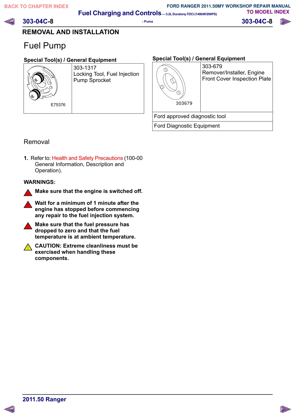
Special Tool(s) / General Equipment
303-1317
Locking Tool, Fuel Injection
Pump Sprocket
E75376
Removal
1. Refer to: Health and Safety Precautions (100-00
General Information, Description and
Operation).
WARNINGS:
Make sure that the engine is switched off.
Wait for a minimum of 1 minute after the
engine has stopped before commencing
any repair to the fuel injection system.
Make sure that the fuel pressure has
dropped to zero and that the fuel
temperature is at ambient temperature.
CAUTION: Extreme cleanliness must be
exercised when handling these
components.
Special Tool(s) / General Equipment
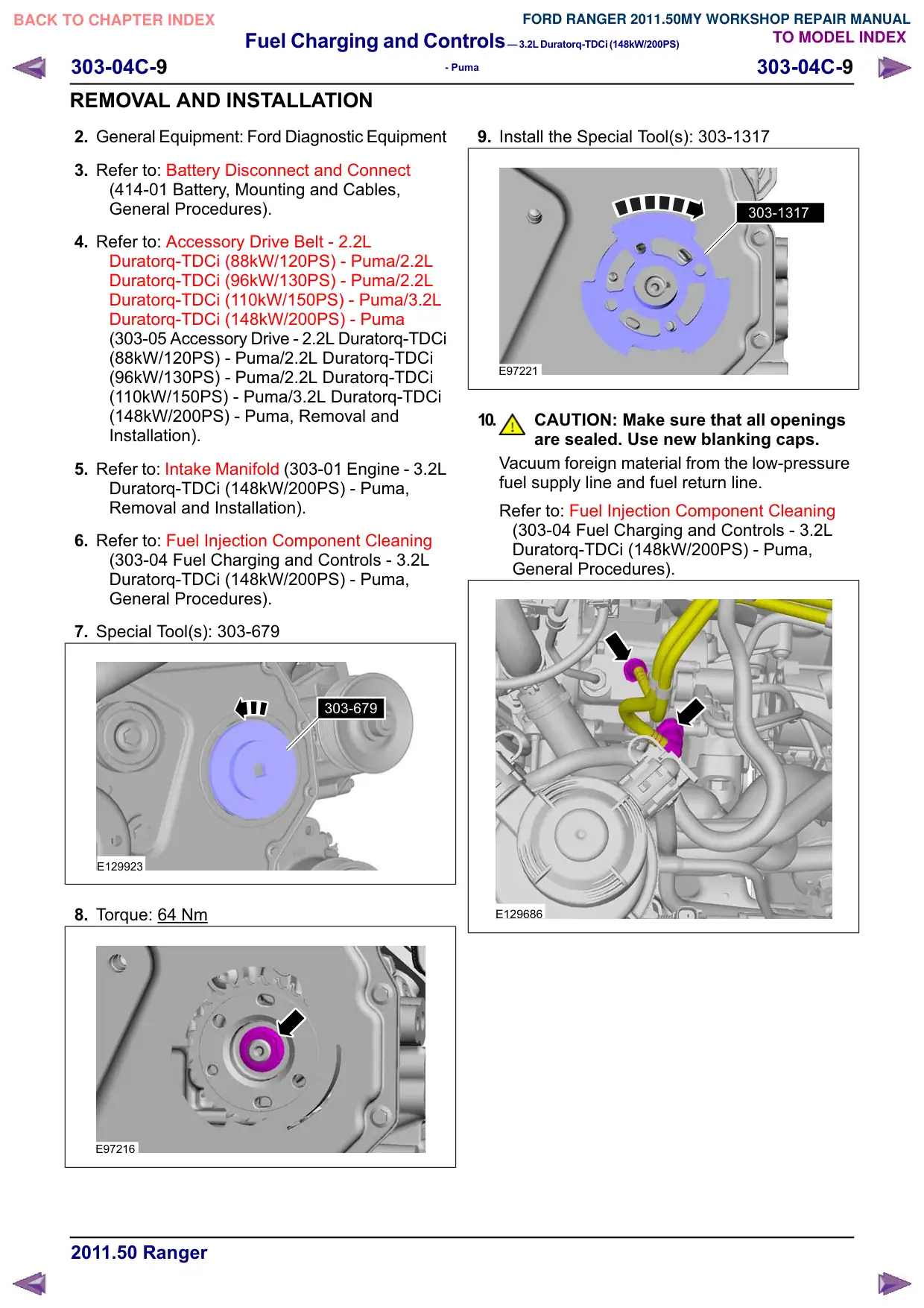
303-679
Remover/Installer, Engine
Front Cover Inspection Plate
303679
Ford approved diagnostic tool
Ford Diagnostic Equipment
Fuel Charging and Controls–3.2LDuratorq-TDCi(148kW/200PS)
303-04C-10
303-04C-10
- Puma
REMOVAL AND INSTALLATION
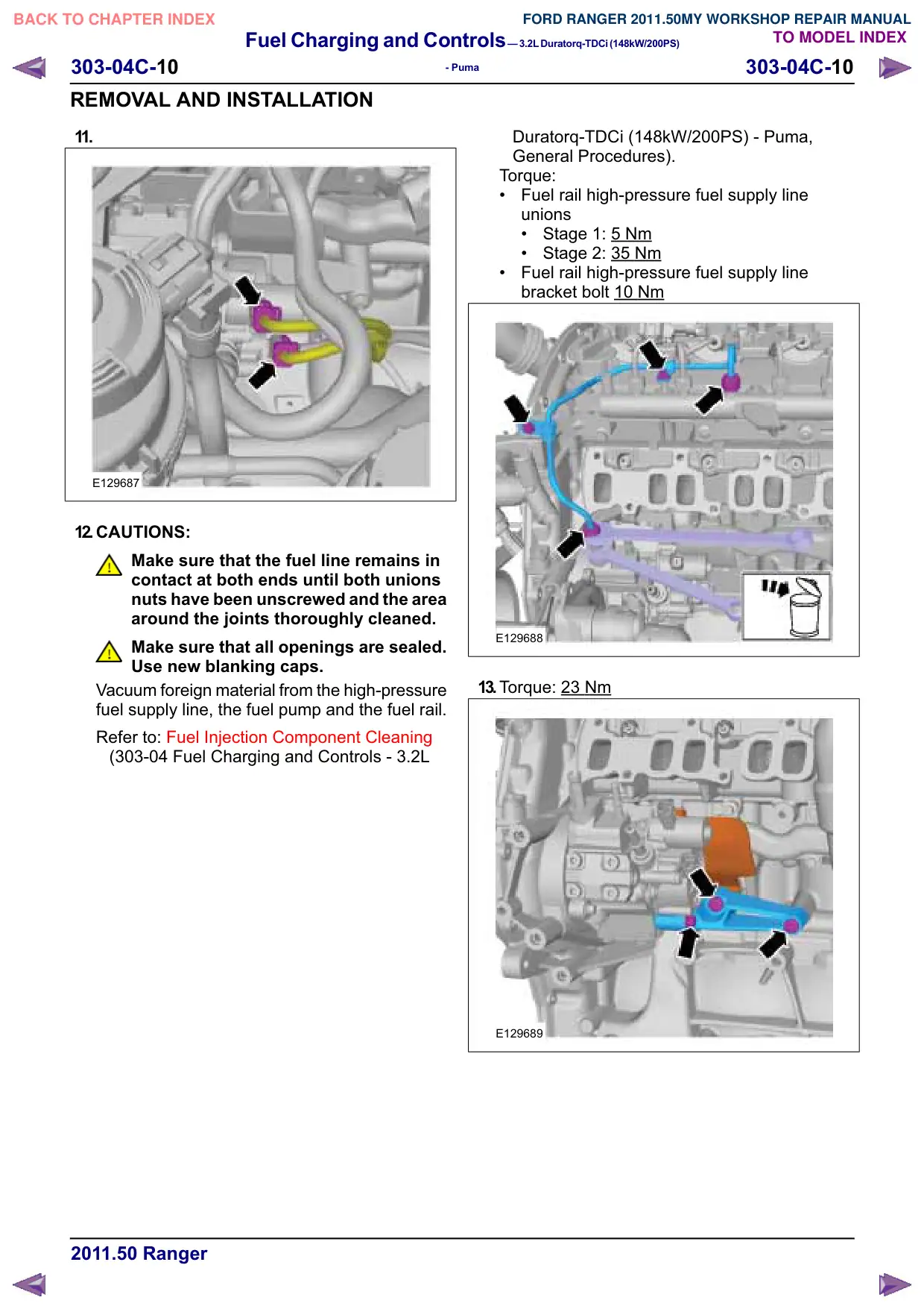
11.
E129687
12.CAUTIONS:
Make sure that the fuel line remains in
contact at both ends until both unions
nuts have been unscrewed and the area
around the joints thoroughly cleaned.
Make sure that all openings are sealed.
Use new blanking caps.
Vacuum foreign material from the high-pressure
fuel supply line, the fuel pump and the fuel rail.
Refer to: Fuel Injection Component Cleaning
(303-04 Fuel Charging and Controls - 3.2L
Duratorq-TDCi (148kW/200PS) - Puma,
General Procedures).
Torque:
Fuel rail high-pressure fuel supply line
unions
Stage 1: 5
Nm
Stage 2: 35 Nm
Fuel rail high-pressure fuel supply line
bracket bolt 10
Nm
E129688
13.Torque: 23 Nm
E129689
Fuel Charging and Controls–3.2LDuratorq-TDCi(148kW/200PS)
303-04C-11
303-04C-11
- Puma
REMOVAL AND INSTALLATION
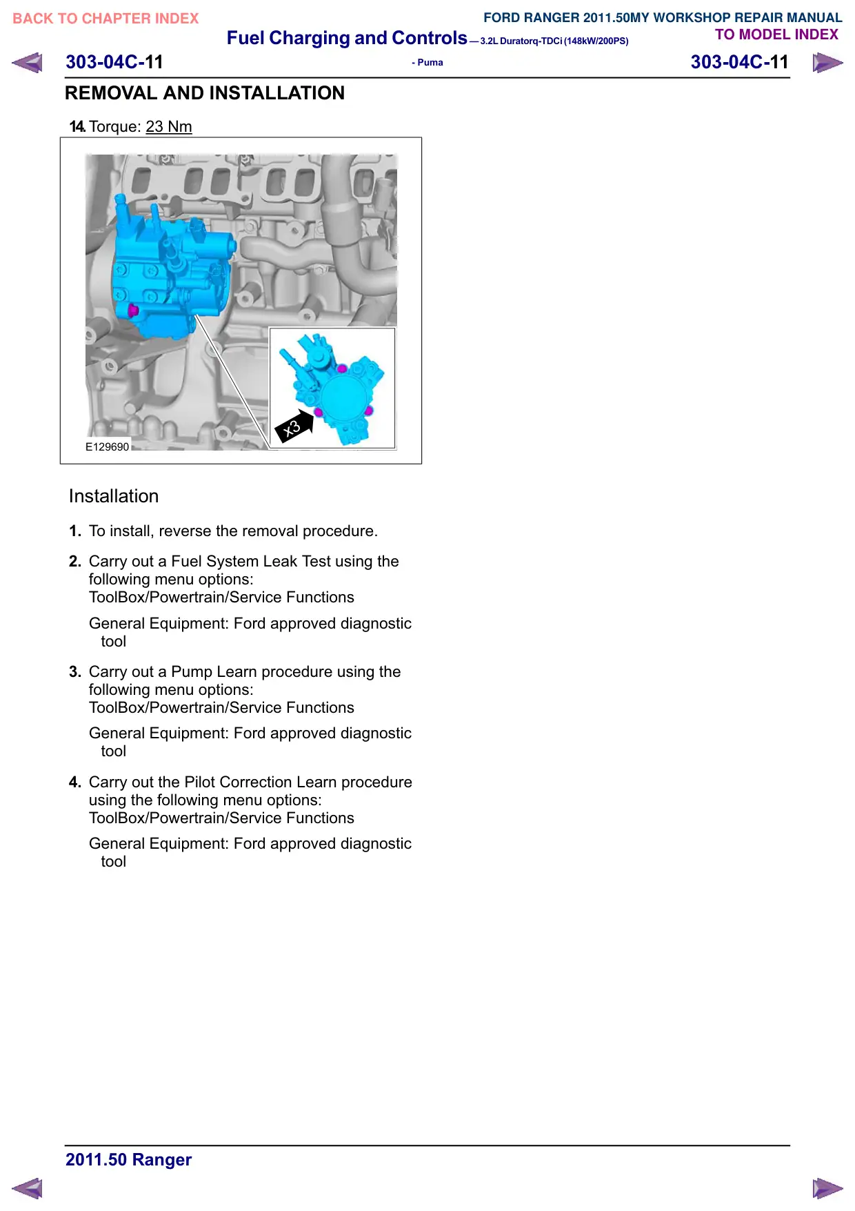
14.Torque: 23 Nm
x3
E129690
Installation
1. To install, reverse the removal procedure.
2. Carry out a Fuel System Leak Test using the
following menu options:
ToolBox/Powertrain/Service Functions
General Equipment: Ford approved diagnostic
tool
3. Carry out a Pump Learn procedure using the
following menu options:
ToolBox/Powertrain/Service Functions
General Equipment: Ford approved diagnostic
tool
4. Carry out the Pilot Correction Learn procedure
using the following menu options:
ToolBox/Powertrain/Service Functions
General Equipment: Ford approved diagnostic
tool
Fuel Charging and Controls–3.2LDuratorq-TDCi(148kW/200PS)
303-04C-12
303-04C-12
- Puma
REMOVAL AND INSTALLATION
Fuel Rail
General Equipment
Ford Diagnostic Equipment
Removal
1. WARNINGS:
Make sure that the engine is switched
off.
Make sure that the fuel pressure has
dropped to zero and that the fuel
temperature is at ambient temperature.
Wait at least 1 minute after the engine
has stopped before commencing any
repair to the fuel injection system.
CAUTION: Always carry out the cleaning
process before carrying out any repairs
to the fuel injection system components.
NOTE: Removal steps in this procedure may
contain installation details.
2. Within the datalogger function, check that the
fuel pressure has dropped to zero and that the
fuel temperature has either reached ambient
temperature or is below 30ºC whichever is the
greater.
General Equipment: Ford Diagnostic Equipment
3. Refer to: Battery Disconnect and Connect
(414-01 Battery, Mounting and Cables,
General Procedures).
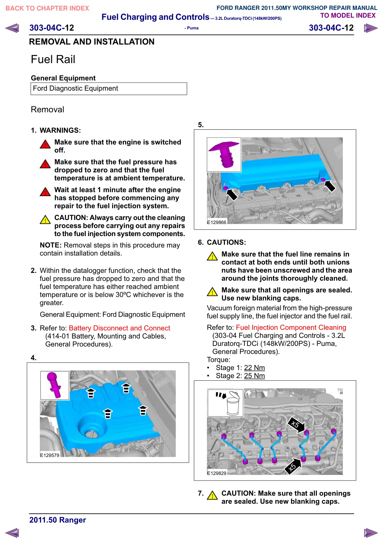
4.
E129579
5.
E129866
6. CAUTIONS:
Make sure that the fuel line remains in
contact at both ends until both unions
nuts have been unscrewed and the area
around the joints thoroughly cleaned.
Make sure that all openings are sealed.
Use new blanking caps.
Vacuum foreign material from the high-pressure
fuel supply line, the fuel injector and the fuel rail.
Refer to: Fuel Injection Component Cleaning
(303-04 Fuel Charging and Controls - 3.2L
Duratorq-TDCi (148kW/200PS) - Puma,
General Procedures).
Torque:
Stage 1: 22 Nm
Stage 2: 25 Nm
x5
x5
E129829
7.
CAUTION: Make sure that all openings
are sealed. Use new blanking caps.
Fuel Charging and Controls–3.2LDuratorq-TDCi(148kW/200PS)
303-04C-13
303-04C-13
- Puma
REMOVAL AND INSTALLATION
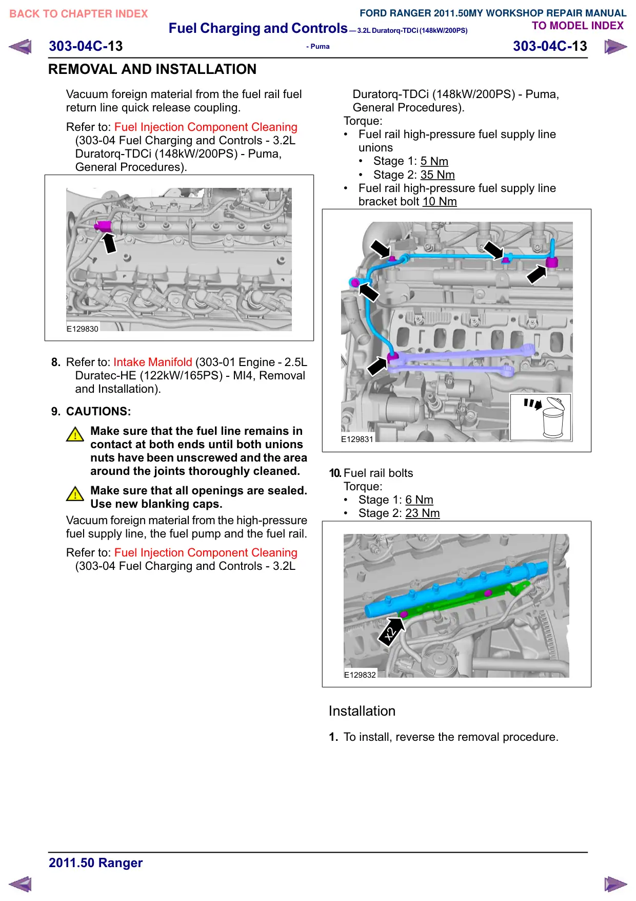
Vacuum foreign material from the fuel rail fuel
return line quick release coupling.
Refer to: Fuel Injection Component Cleaning
(303-04 Fuel Charging and Controls - 3.2L
Duratorq-TDCi (148kW/200PS) - Puma,
General Procedures).
E129830
8. Refer to: Intake Manifold (303-01 Engine - 2.5L
Duratec-HE (122kW/165PS) - MI4, Removal
and Installation).
9. CAUTIONS:
Make sure that the fuel line remains in
contact at both ends until both unions
nuts have been unscrewed and the area
around the joints thoroughly cleaned.
Make sure that all openings are sealed.
Use new blanking caps.
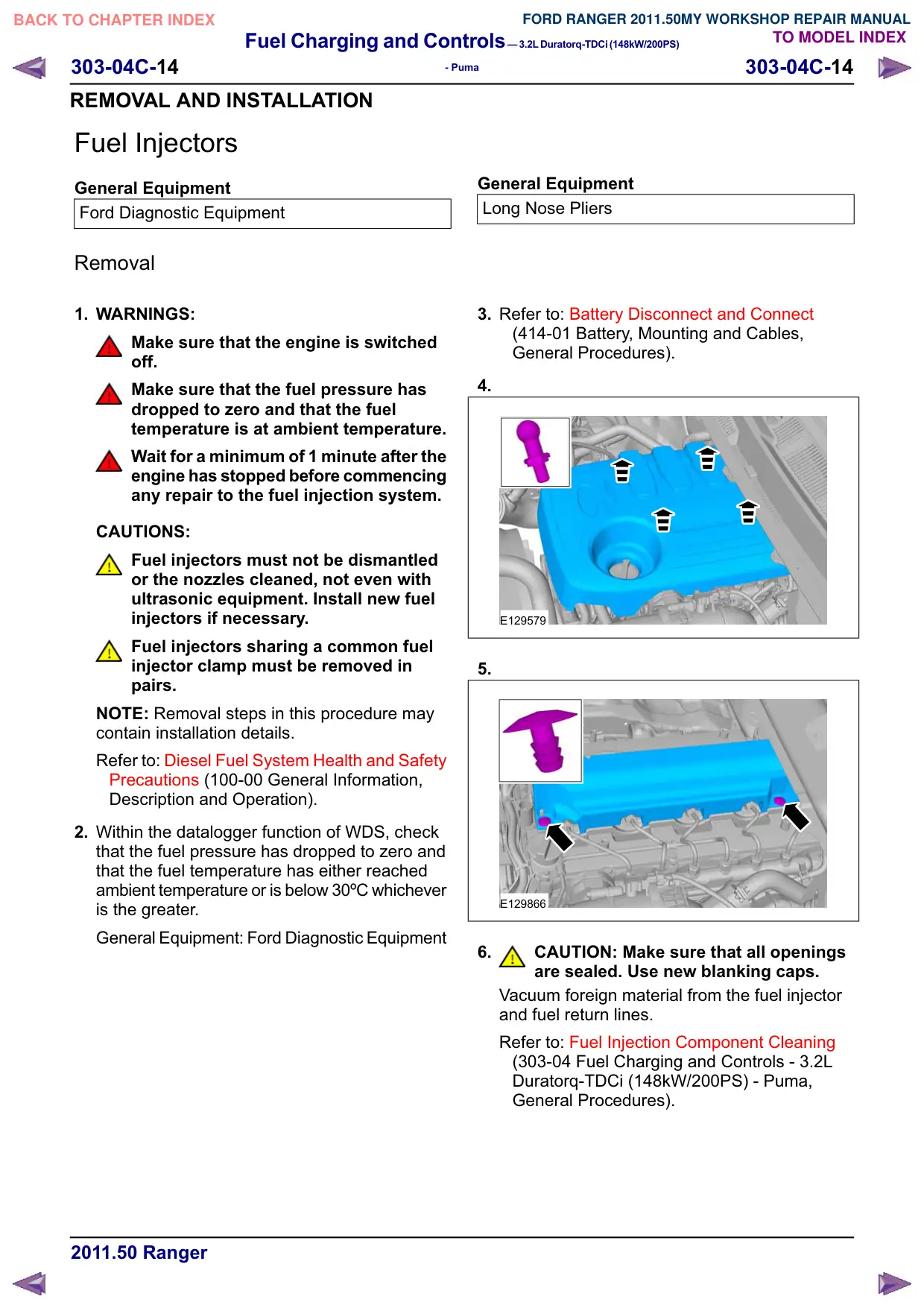
Vacuum foreign material from the high-pressure
fuel supply line, the fuel pump and the fuel rail.
Refer to: Fuel Injection Component Cleaning
(303-04 Fuel Charging and Controls - 3.2L
Duratorq-TDCi (148kW/200PS) - Puma,
General Procedures).
Torque:
Fuel rail high-pressure fuel supply line
unions
Stage 1: 5 Nm
Stage 2: 35 Nm
Fuel rail high-pressure fuel supply line
bracket bolt 10 Nm
E129831
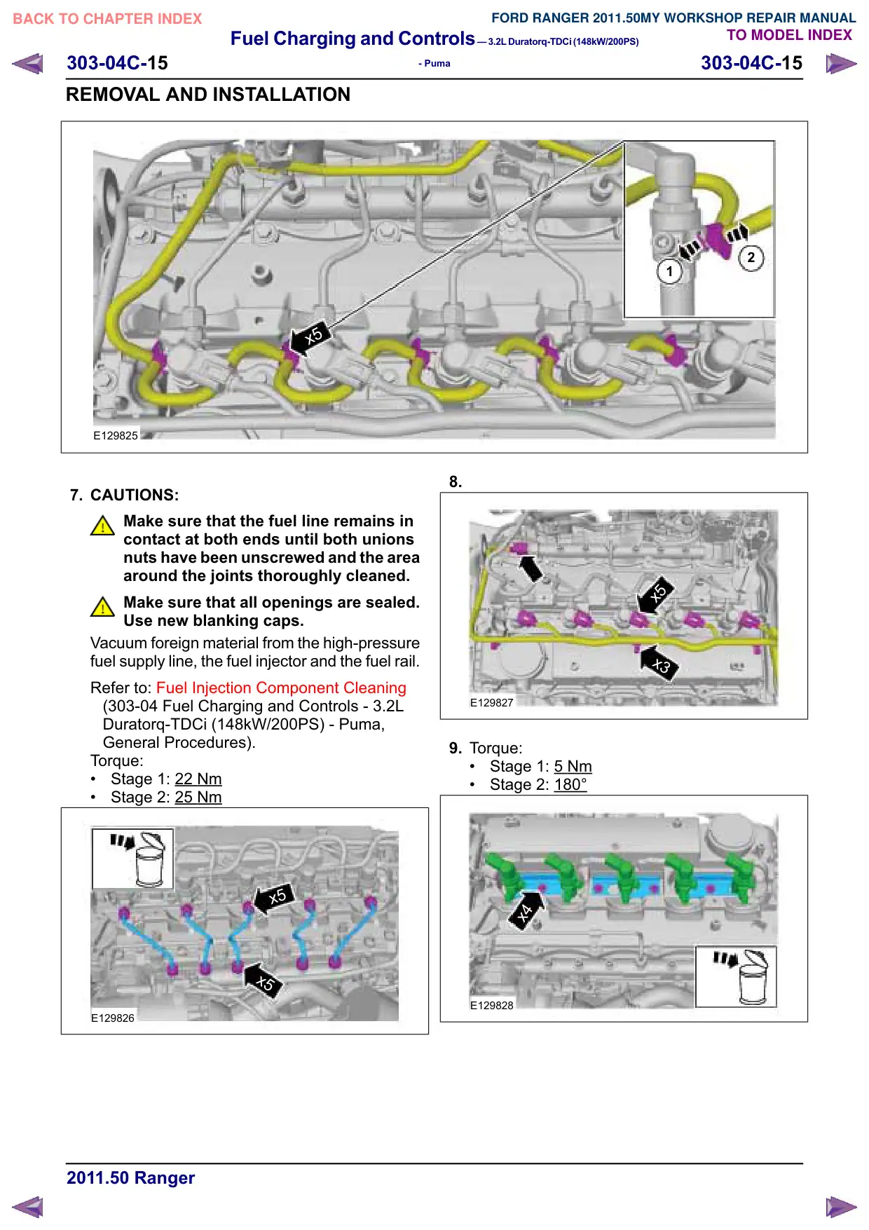
10.Fuel rail bolts
Torque:
Stage 1: 6 Nm
Stage 2: 23 Nm
x2
E129832
Installation
1. To install, reverse the removal procedure.
Fuel Charging and Controls–3.2LDuratorq-TDCi(148kW/200PS)
303-04C-14
303-04C-14
- Puma
REMOVAL AND INSTALLATION
Fuel Injectors
General Equipment
Ford Diagnostic Equipment
Removal
1. WARNINGS:
Make sure that the engine is switched
off.
Make sure that the fuel pressure has
dropped to zero and that the fuel
temperature is at ambient temperature.
Wait for a minimum of 1 minute after the
engine has stopped before commencing
any repair to the fuel injection system.
CAUTIONS:
Fuel injectors must not be dismantled
or the nozzles cleaned, not even with
ultrasonic equipment. Install new fuel
injectors if necessary.
Fuel injectors sharing a common fuel
injector clamp must be removed in
pairs.
NOTE: Removal steps in this procedure may
contain installation details.
Refer to: Diesel Fuel System Health and Safety
Precautions (100-00 General Information,
Description and Operation).
2. Within the datalogger function of WDS, check
that the fuel pressure has dropped to zero and
that the fuel temperature has either reached
ambient temperature or is below 30ºC whichever
is the greater.
General Equipment: Ford Diagnostic Equipment
General Equipment
Long Nose Pliers
3. Refer to: Battery Disconnect and Connect
(414-01 Battery, Mounting and Cables,
General Procedures).
4.
E129579
5.
E129866
6.
CAUTION: Make sure that all openings
are sealed. Use new blanking caps.
Vacuum foreign material from the fuel injector
and fuel return lines.
Refer to: Fuel Injection Component Cleaning
(303-04 Fuel Charging and Controls - 3.2L
Duratorq-TDCi (148kW/200PS) - Puma,
General Procedures).
Fuel Charging and Controls–3.2LDuratorq-TDCi(148kW/200PS)
303-04C-15
303-04C-15
- Puma
REMOVAL AND INSTALLATION
x5
E129825
7. CAUTIONS:
Make sure that the fuel line remains in
contact at both ends until both unions
nuts have been unscrewed and the area
around the joints thoroughly cleaned.
Make sure that all openings are sealed.
Use new blanking caps.
Vacuum foreign material from the high-pressure
fuel supply line, the fuel injector and the fuel rail.
Refer to: Fuel Injection Component Cleaning
(303-04 Fuel Charging and Controls - 3.2L
Duratorq-TDCi (148kW/200PS) - Puma,
General Procedures).
Torque:
Stage 1: 22
Nm
Stage 2: 25 Nm
x5
x5
E129826
2
1
8.
x5
x3
E129827
9. Torque:
Stage 1: 5 Nm
Stage 2: 180°
x4
E129828
Fuel Charging and Controls–3.2LDuratorq-TDCi(148kW/200PS)
303-04C-16
303-04C-16
- Puma
REMOVAL AND INSTALLATION
10.General Equipment: Long Nose Pliers
E129584
Installation
1. To install, reverse the removal procedure.
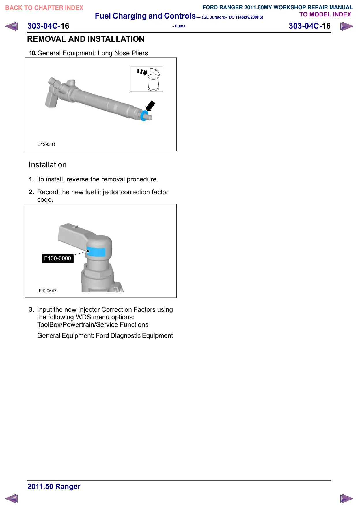
2. Record the new fuel injector correction factor
code.
F100-0000
E129647
3. Input the new Injector Correction Factors using
the following WDS menu options:
ToolBox/Powertrain/Service Functions
General Equipment: Ford Diagnostic Equipment