Steering Column
211-04-2
211-04-2
REMOVAL AND INSTALLATION
Steering Wheel(13 524 0)
General Equipment
Adhesive Tape
Removal
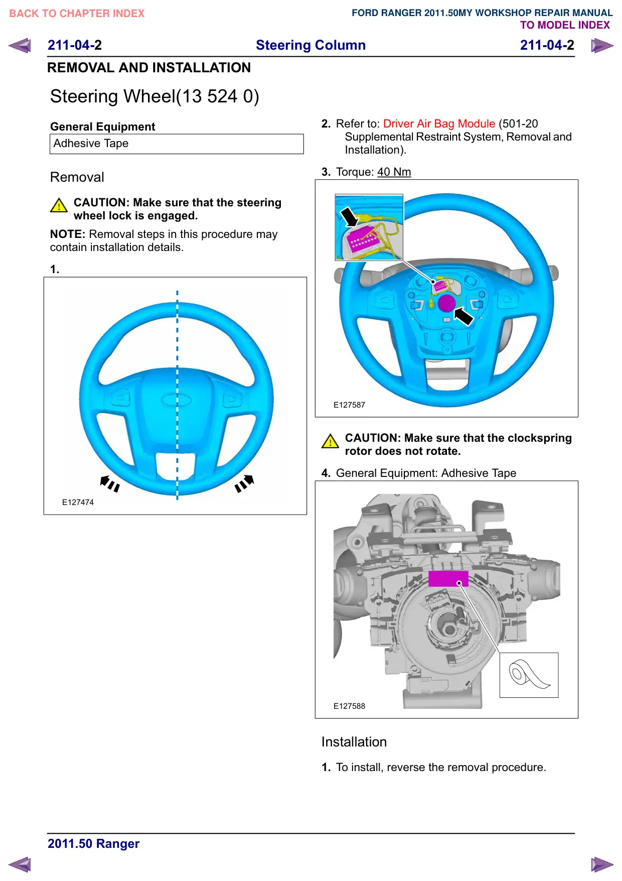
CAUTION: Make sure that the steering
wheel lock is engaged.
NOTE: Removal steps in this procedure may
contain installation details.
1.
E127474
2. Refer to: Driver Air Bag Module (501-20
Supplemental Restraint System, Removal and
Installation).
3. Torque: 40 Nm
E127587
CAUTION: Make sure that the clockspring
rotor does not rotate.
4. General Equipment: Adhesive Tape
E127588
Installation
1. To install, reverse the removal procedure.
Steering Column
211-04-3
211-04-3
REMOVAL AND INSTALLATION
Steering Column(13 542 0)
General Equipment
Ford Diagnostic Equipment
Removal
NOTE: Removal steps in this procedure may
contain installation details.
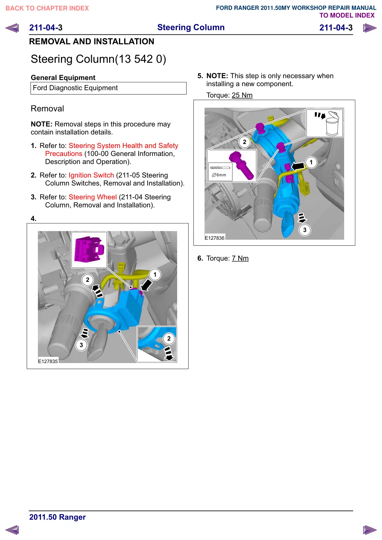
1. Refer to: Steering System Health and Safety
Precautions (100-00 General Information,
Description and Operation).
2. Refer to: Ignition Switch (211-05 Steering
Column Switches, Removal and Installation).
3. Refer to: Steering Wheel (211-04 Steering
Column, Removal and Installation).
4.
1
2
2
3
E127835
5. NOTE: This step is only necessary when
installing a new component.
Torque: 25 Nm
2
1
6mm
3
E127836
6. Torque: 7 Nm
211-04-4
Steering Column
211-04-4
REMOVAL AND INSTALLATION
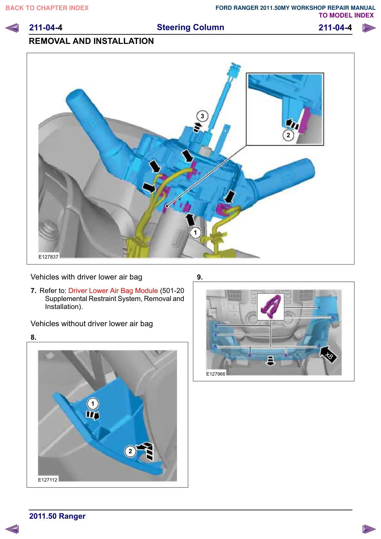
E127837
Vehicles with driver lower air bag
7. Refer to: Driver Lower Air Bag Module (501-20
Supplemental Restraint System, Removal and
Installation).
Vehicles without driver lower air bag
8.
1
2
E127112
3
2
1
9.
x8
E127966
211-04-5
Steering Column
211-04-5
REMOVAL AND INSTALLATION
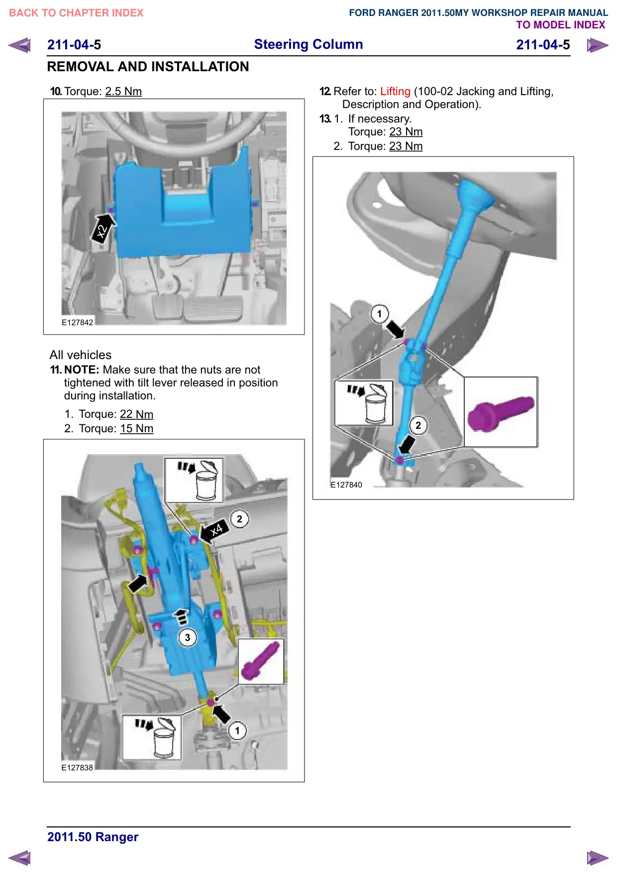
10.Torque: 2.5 Nm
x2
E127842
All vehicles
11. NOTE: Make sure that the nuts are not
tightened with tilt lever released in position
during installation.
1. Torque: 22
Nm
2. Torque: 15 Nm
2
x4
3
1
E127838
12.Refer to: Lifting (100-02 Jacking and Lifting,
Description and Operation).
13.
1.
If necessary.
Torque: 23
Nm
2. Torque: 23 Nm
1
2
E127840
Steering Column
211-04-6
211-04-6
REMOVAL AND INSTALLATION
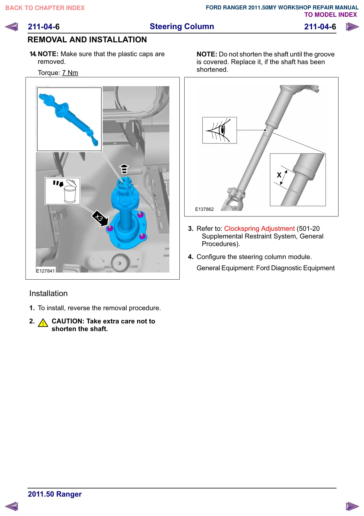
14.NOTE: Make sure that the plastic caps are
removed.
Torque: 7 Nm
x3
E127841
Installation
1. To install, reverse the removal procedure.
2.
CAUTION: Take extra care not to
shorten the shaft.
NOTE: Do not shorten the shaft until the groove
is covered. Replace it, if the shaft has been
shortened.
E137862
3. Refer to: Clockspring Adjustment (501-20
Supplemental Restraint System, General
Procedures).
4. Configure the steering column module.
General Equipment: Ford Diagnostic Equipment